EP0765670A1 - Procédé et dispositif de contrôle de la sécurité d'emploi de la membrane d'un dialysateur - Google Patents
Procédé et dispositif de contrôle de la sécurité d'emploi de la membrane d'un dialysateur Download PDFInfo
- Publication number
- EP0765670A1 EP0765670A1 EP96115020A EP96115020A EP0765670A1 EP 0765670 A1 EP0765670 A1 EP 0765670A1 EP 96115020 A EP96115020 A EP 96115020A EP 96115020 A EP96115020 A EP 96115020A EP 0765670 A1 EP0765670 A1 EP 0765670A1
- Authority
- EP
- European Patent Office
- Prior art keywords
- dialysis fluid
- blood
- dialyzer
- membrane
- flow
- Prior art date
- Legal status (The legal status is an assumption and is not a legal conclusion. Google has not performed a legal analysis and makes no representation as to the accuracy of the status listed.)
- Granted
Links
- 239000012528 membrane Substances 0.000 title claims abstract description 44
- 238000000034 method Methods 0.000 title claims abstract description 20
- 210000004369 blood Anatomy 0.000 claims abstract description 100
- 239000008280 blood Substances 0.000 claims abstract description 100
- 239000000385 dialysis solution Substances 0.000 claims abstract description 87
- 238000000108 ultra-filtration Methods 0.000 claims abstract description 28
- 238000001631 haemodialysis Methods 0.000 claims abstract description 21
- 238000012544 monitoring process Methods 0.000 claims abstract description 7
- 230000000322 hemodialysis Effects 0.000 claims description 20
- 238000011156 evaluation Methods 0.000 claims description 4
- 230000037361 pathway Effects 0.000 claims 1
- 210000004379 membrane Anatomy 0.000 description 38
- 238000000502 dialysis Methods 0.000 description 24
- 239000007788 liquid Substances 0.000 description 15
- 238000001914 filtration Methods 0.000 description 6
- 230000017531 blood circulation Effects 0.000 description 5
- 239000000126 substance Substances 0.000 description 5
- 238000012360 testing method Methods 0.000 description 5
- 210000004027 cell Anatomy 0.000 description 4
- 239000012530 fluid Substances 0.000 description 4
- 230000002485 urinary effect Effects 0.000 description 4
- XLYOFNOQVPJJNP-UHFFFAOYSA-N water Substances O XLYOFNOQVPJJNP-UHFFFAOYSA-N 0.000 description 4
- 102000001554 Hemoglobins Human genes 0.000 description 3
- 108010054147 Hemoglobins Proteins 0.000 description 3
- 239000000243 solution Substances 0.000 description 3
- 208000031729 Bacteremia Diseases 0.000 description 2
- 238000006243 chemical reaction Methods 0.000 description 2
- 235000008504 concentrate Nutrition 0.000 description 2
- 239000012141 concentrate Substances 0.000 description 2
- 238000011109 contamination Methods 0.000 description 2
- 238000010586 diagram Methods 0.000 description 2
- 238000009792 diffusion process Methods 0.000 description 2
- 238000010438 heat treatment Methods 0.000 description 2
- 238000005259 measurement Methods 0.000 description 2
- 230000003287 optical effect Effects 0.000 description 2
- 230000001698 pyrogenic effect Effects 0.000 description 2
- 230000001960 triggered effect Effects 0.000 description 2
- FAPWRFPIFSIZLT-UHFFFAOYSA-M Sodium chloride Chemical compound [Na+].[Cl-] FAPWRFPIFSIZLT-UHFFFAOYSA-M 0.000 description 1
- 210000001367 artery Anatomy 0.000 description 1
- 230000005540 biological transmission Effects 0.000 description 1
- 230000036770 blood supply Effects 0.000 description 1
- 230000036760 body temperature Effects 0.000 description 1
- 208000020832 chronic kidney disease Diseases 0.000 description 1
- 208000022831 chronic renal failure syndrome Diseases 0.000 description 1
- 238000001514 detection method Methods 0.000 description 1
- 239000006185 dispersion Substances 0.000 description 1
- 210000003743 erythrocyte Anatomy 0.000 description 1
- 239000012510 hollow fiber Substances 0.000 description 1
- 239000012535 impurity Substances 0.000 description 1
- 210000003734 kidney Anatomy 0.000 description 1
- 235000014666 liquid concentrate Nutrition 0.000 description 1
- 230000014759 maintenance of location Effects 0.000 description 1
- 239000000203 mixture Substances 0.000 description 1
- 230000035699 permeability Effects 0.000 description 1
- 230000008092 positive effect Effects 0.000 description 1
- 239000000523 sample Substances 0.000 description 1
- 239000012488 sample solution Substances 0.000 description 1
- 230000035945 sensitivity Effects 0.000 description 1
- 238000002834 transmittance Methods 0.000 description 1
- 210000003462 vein Anatomy 0.000 description 1
Images

Classifications
-
- B—PERFORMING OPERATIONS; TRANSPORTING
- B01—PHYSICAL OR CHEMICAL PROCESSES OR APPARATUS IN GENERAL
- B01D—SEPARATION
- B01D65/00—Accessories or auxiliary operations, in general, for separation processes or apparatus using semi-permeable membranes
- B01D65/10—Testing of membranes or membrane apparatus; Detecting or repairing leaks
- B01D65/102—Detection of leaks in membranes
-
- A—HUMAN NECESSITIES
- A61—MEDICAL OR VETERINARY SCIENCE; HYGIENE
- A61M—DEVICES FOR INTRODUCING MEDIA INTO, OR ONTO, THE BODY; DEVICES FOR TRANSDUCING BODY MEDIA OR FOR TAKING MEDIA FROM THE BODY; DEVICES FOR PRODUCING OR ENDING SLEEP OR STUPOR
- A61M1/00—Suction or pumping devices for medical purposes; Devices for carrying-off, for treatment of, or for carrying-over, body-liquids; Drainage systems
- A61M1/14—Dialysis systems; Artificial kidneys; Blood oxygenators ; Reciprocating systems for treatment of body fluids, e.g. single needle systems for hemofiltration or pheresis
- A61M1/16—Dialysis systems; Artificial kidneys; Blood oxygenators ; Reciprocating systems for treatment of body fluids, e.g. single needle systems for hemofiltration or pheresis with membranes
- A61M1/1692—Detection of blood traces in dialysate
-
- B—PERFORMING OPERATIONS; TRANSPORTING
- B01—PHYSICAL OR CHEMICAL PROCESSES OR APPARATUS IN GENERAL
- B01D—SEPARATION
- B01D61/00—Processes of separation using semi-permeable membranes, e.g. dialysis, osmosis or ultrafiltration; Apparatus, accessories or auxiliary operations specially adapted therefor
- B01D61/24—Dialysis ; Membrane extraction
- B01D61/32—Controlling or regulating
Definitions
- the invention relates to a method for monitoring the functional reliability of the membrane of the dialyzer of a hemodialysis machine with an ultrafiltration device during the hemodialysis treatment and a device for carrying out the method in connection with a hemodialysis machine which has a device for setting the ultrafiltration rate and a blood leak detector arranged in the dialysis fluid path.
- Hemodialysis is a treatment method for chronic kidney failure.
- the patient's blood is cleaned outside the body in an artificial kidney, which is also called a dialyzer.
- the dialyzer has a blood chamber and a dialysis fluid chamber, which are separated by a semipermeable membrane.
- the membrane generally consists of plates or hollow fibers and has a total surface area of 1 to 2 m 2 . The integrity of the membrane ensures that the blood is separated from the dialysis fluid.
- the dialysis fluid chamber is continuously flowed through by fresh dialysis fluid.
- liquid is also generally withdrawn from the blood.
- a suction device This process is known as ultra filtration.
- a hemodialysis machine with such an ultrafiltration device is known for example from DE-A-22 59 787.
- a known safety system comprises a blood leak detector which monitors the membrane of the dialyzer for leaks which lead to blood entering the dialysis fluid circuit from the blood circulation.
- blood in the dialysis fluid is generally detected by means of a photo-optical sensor with which the concentration of blood in the dialysis fluid can be determined.
- the blood leak detectors are often operated in the flow and generate a signal when a predetermined limit value is exceeded.
- various measures can be taken. An alarm can be triggered and the power supply to the blood pump can be interrupted.
- the dialyzer is also bypassed using a bypass line.
- Blood leak detectors are known in various embodiments.
- US Pat. No. 4,181,610 describes a blood leak detector with an optical measuring cell through which the dialysis fluid flows during the test phase.
- Two light-emitting diodes are arranged on one side of the measuring cell and a photo-optical sensor is located on the other side of the measuring cell.
- One of the light emitting diodes emits light with a longer wavelength, while the other light emitting diode emits light with a shorter wavelength. Both diodes are operated in such a way that the photo-optical sensor signals the same strength if there is no blood in the measuring cell.
- the signals from the photo-optical sensor are received and evaluated in order to generate signals which are deflected in one direction depending on the size of the blood leak, if such occurs.
- signals which are deflected in one direction depending on the size of the blood leak, if such occurs.
- air bubbles When air bubbles are detected, they result in signals in the other direction, which is due to the fact that blood absorbs light with a shorter wavelength more, while air bubbles absorb light with longer wavelength more strongly.
- US-A-4,017,190 describes a system for the detection of small amounts of hemoglobin in a solution by detecting the relationship between light transmission at different wavelengths in a sample solution, one of these wavelengths being of the order of magnitude at which hemoglobin strongly absorbs light. Since the ratio of the signals is important, a measurement with high sensitivity and linearity is possible if there is contamination and turbidity in the sample or in the system.
- a colorimeter for detecting a blood leak in a dialysis machine is known from US Pat. No. 3,832,067.
- the colorimeter detects the presence of an impurity that is opaque to light of a particular color that enters the liquid flow.
- a photocell on one side of the liquid flow is illuminated only with light of the particular color coming from the opposite side of the liquid flow, the photocell detecting a change in the intensity of the light passing through, due to the presence is due to contamination.
- US-A-3,900,396 proposes a blood leak detector consisting of a transparent line through which dialysis fluid circulates through a block.
- the block contains a lamp whose light passes through a first channel in the Block that slants the line and enters a second channel in the block.
- the second channel has the same length as the first channel and runs obliquely to the first channel without cutting it.
- Identical 550 to 560 nm filters and photocells are arranged at the two ends of the channels.
- the channels create relatively wide dispersion angles.
- a circuit is provided to measure the difference signal of the photocells and to express this in the form of a voltage. If the difference between this voltage and a reference voltage is above a certain limit, an alarm is triggered.
- US-A-4,060,485 describes a dialysis machine with a conventional blood leak detector which has a photoelectric device for detecting blood in a saline solution, which indicates a leak or fault in the dialysis unit.
- the blood leak detector provides an electrical signal to a logic circuit which activates a signal lamp or an audible alarm that indicates that blood leakage has occurred.
- the pressure difference between blood and dialysis fluid is generally positive over the entire length of the membrane. If the membrane is then damaged, blood can get into the dialysis fluid and thus into the drain.
- the known blood leak detectors respond, which are arranged in the dialysis fluid path.
- the known blood leak detectors have the disadvantage that leakage points in the membrane cannot be determined during a so-called high-flux dialysis treatment.
- dialyzers with high permeability which are also referred to as high-flux dialyzers
- a condition can occur during dialysis treatment in which there is a net pressure drop from the blood side to the dialysis fluid side, but areas form in the dialyzer in which the Pressure in the dialysis fluid is higher than the pressure in Blood.
- a so-called “back-filtration” takes place, ie "filtered” dialysis fluid reaches the patient via the dialyzer.
- this can have a positive effect on the treatment quality. If the membrane is damaged, however, unfiltered dialysis fluid can get into the bloodstream during "back-filtration".
- dialysis fluid that is not sterile through suitable measures, such as online filtration gets into the bloodstream, serious complications, such as pyrogenic reactions or bacteremia, can occur. This cannot be prevented with the known blood leak detectors.
- the invention has for its object to provide a method and a device with which the safety of a hemodialysis machine can be further increased.
- the integrity of the membrane of the dialyzer is checked by controlling the dialysis fluid flow and the ultrafiltration rate.
- the flow of the dialysis fluid through the dialysis fluid chamber of the dialyzer is interrupted and the ultrafiltration rate is increased to ensure that a pressure gradient from the blood to the dialysis fluid is established at every point of the membrane.
- the amount of liquid withdrawn can be added to the total withdrawal volume. If there is now a passage of blood into the dialysis fluid due to leaks in the membrane, the blood leakage in the dialysis fluid path can be detected as soon as the dialysis fluid flow is started again becomes.
- the interruption of the flow leads to a concentration, so that the blood can be detected in the dialysis fluid path using the known blood leak detectors.
- the ultrafiltration rate is preferably increased for a period of at least 20 seconds. To achieve reliable measurement results, however, it is sufficient if the ultrafiltration rate is increased for a period of not more than 60 seconds.
- An ultrafiltration rate of ⁇ 500 ml / min ensures that a pressure gradient from the blood to the dialysis fluid is established at every point on the membrane.
- the device according to the invention for carrying out the method has a control unit with a timer, which is designed such that the flow of the dialysis fluid through the dialysis fluid chamber of the dialyzer is interrupted for a predetermined time interval and the ultrafiltration rate can be increased to a predetermined value in the predetermined time interval.
- the blood leakage in the dialysis fluid path is detected by means of a blood leak detector, the output signal of which is monitored by an evaluation unit.
- the flow of the dialysis fluid through the dialysis fluid chamber of the dialyzer is interrupted when a transmembrane pressure that is negative compared to the dialysate side of the membrane occurs on the blood side. Since the test phase is initiated automatically, it can be prevented that blood gets into the dialysis fluid path in the event of backfiltration. However, it is also possible for the flow of the dialysis liquid to be interrupted periodically at predetermined time intervals.
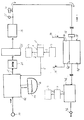
- FIG. 1 shows a single-user dialysis machine in a schematic representation.
- the method according to the invention can also be applied to other dialysis machines which, for example, have a closed dialysis fluid circuit.
- the entire system is rinsed and air bubbles are removed.
- the patient is connected to the dialysis machine by connecting the blood supply line 34 and the blood return line 36 with needles that are inserted into an artery or vein of the patient. Blood is then pumped from the patient through the blood chamber of the dialyzer 38 and back to the patient via the blood lines.
- the proportioning pump 12 controls the mixture of the dialysis liquid.
- water is produced from an inlet 10 with a liquid to produce the dialysis liquid Dialysing fluid concentrate 14 mixed, which is provided in a concentrate container 16.
- the dialysis fluid 18 then passes through a heating device 20, in which the fluid is heated to the body temperature before it is pumped through the dialyzer. Since the inflowing water can carry air bubbles with it, it is necessary to connect an air separator 22 to the heating device 20. To remove air from the dialysis liquid, it is subjected to an extremely negative pressure, generally 300 to 600 mm / Hg, and the air is then separated from the solution.
- a conductivity measuring device 26 is generally used to set the desired mixing ratio of water and dialysis liquid concentrate.
- the temperature and conductivity of the dialysis fluid is monitored by means of display and alarm devices 28, 30 to ensure that the dialysis machine is operating correctly before the dialysis fluid is supplied to the dialyzer 38.
- a flow meter 32 monitors the flow rate of the dialysis fluid entering the dialysis fluid chamber of the dialyzer 38. The importance of the relationship between the flow rate of the dialysis fluid and the flow rate of blood in the dialyzer for the invention is explained below.
- the dialysis fluid emerging from the dialyzer 38 then passes through a blood leak detector 42 arranged downstream of the dialyzer, which detects blood in the dialysis fluid.
- Blood leak detector 42 generally includes a photo-optical sensor that measures a change in optical transmittance due to the scattering of light by hemoglobin that the red blood cells contain in the bloodstream. But it can also be any other type of known blood leak detector Find use.
- the dialysis fluid finally flows from the blood leak detector 42 into a drain 46.
- the dialyzer 38 consists of a blood chamber 50, a dialysis fluid chamber 48 and a semi-permeable membrane 52 which separates the two chambers from one another.
- the urinary substances in the blood which are normally small dissolved substances, can pass from the blood flowing through the blood chamber 50 through the semipermeable membrane 52 into the dialysis fluid chamber 48.
- the membrane 52 separating the two chambers is a semi-permeable membrane with a surface area of approximately 1 to 2 m 2 .
- membranes are offered in numerous embodiments, such membranes have in common that they allow one component of a solution to pass through and prevent the other component from doing so.
- the blood on the blood side flows along the membrane, while the dialysis fluid flows on the other side.
- the flow rate on the blood side is normally 100 ml / min
- the flow rate on the dialysis liquid side is normally in the order of 200 ml / min to 500 ml / min for an adult.
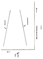
- the pressure gradient in the dialyzer is such that the pressure on the blood side within the entire dialyzer is positive compared to the pressure on the dialysis fluid side, so that in the event of a leak, blood from the blood chamber gets into the dialysis fluid chamber. 2 shows the pressure gradients during normal or low-flux dialysis treatment.
- the state shown in FIG. 3 is also referred to as back-filtration because the dialysis liquid is sterile filtered by means of the dialyzer membrane and enters the blood stream. If a leak occurs in this state, dialysis fluid enters the blood stream from the dialysis fluid side. Since there is no blood in the dialysis fluid flowing out of the dialyzer through the blood leak detector 42, the leak cannot be recognized.
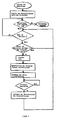
- a preferred exemplary embodiment of the method according to the invention for automatically monitoring the membrane of high-flux dialyzers for leaks in the area of the back-filtration is described below with reference to the flow chart of FIG. 4.
- the dialysis fluid flow is set to a certain value, the treatment being ended after a certain treatment time.
- Membrane integrity is monitored during dialysis treatment. If the transmembrane pressure on the blood side becomes negative compared to the dialysate side of the membrane, the dialysis fluid flow through the dialyzer is automatically interrupted. Otherwise the treatment is continued.
- the ultrafiltration rate is increased to a value ⁇ 500 ml / min for a period of more than 20 seconds. If there is a positive pressure on the blood side again, the dialyzer is supplied with dialysis fluid again. The dialysis fluid then flows out of the machine through the blood leak detector.
- a period of 20 seconds is sufficient with ultrafiltration for blood to pass through the membrane into the dialysis fluid.
- the ultrafiltrate enriched with blood then passes the blood leak detector, which indicates a leak. If a blood leak has been detected, the blood pump provided in the blood circulation can be stopped and the dialyzer can be bridged by a bypass line.
- the device for automatically checking the integrity of the membrane of the dialyzer 38 has a control unit 1 with a timing element 1 ', which is connected via data lines 2 on the one hand to a device for monitoring the transmembrane pressure 3 and on the other hand to the device 4 of the hemodialysis machine for setting the ultrafiltration rate stands (Fig. 1).
- the control unit 1 for controlling the dialysis fluid flow is connected to the proportioning pump 12 via a further data line 5.
- the blood leak detector 42 is connected via a data line 6 to an evaluation unit 7, which is connected to an alarm device 9 via a data line 8.
- the control unit 1 is designed in such a way that the flow of the dialysis fluid through the dialyzer 38 is automatically interrupted for a time interval of 20 seconds predetermined by the timing element 1 'when on the blood side by means of the device 3 for monitoring the transmembrane pressure compared to the dialysate side Membrane negative transmembrane pressure is measured.
- the control unit 1 controls the device 4 for setting the ultrafiltration rate in such a way that the ultrafiltration rate is increased to a value of 500 ml / min for the predetermined period of 20 seconds.
- the control unit 1 sets the ultrafiltration rate and the dialysis fluid flow back to the normal values.
- the evaluation unit 7 compares the output signal of the blood leak detector 42 with a predetermined limit value. If the output signal of the blood leak detector 42 is above the limit value in the event of a leak, the latter emits a signal to the alarm device 9, which triggers an alarm function.
- the alarm device 9 can, for example, interrupt the power supply to the blood pump arranged in the blood circulation, which is not shown in FIG. 1. In the embodiment of the device for checking the membrane integrity described with reference to FIG. 1, the integrity test is carried out when back-filtration occurs. However, it is also possible for the integrity test to be carried out periodically at predetermined fixed time intervals, regardless of the transmembrane pressure.
Landscapes
- Health & Medical Sciences (AREA)
- Chemical Kinetics & Catalysis (AREA)
- Urology & Nephrology (AREA)
- Chemical & Material Sciences (AREA)
- Engineering & Computer Science (AREA)
- Heart & Thoracic Surgery (AREA)
- Anesthesiology (AREA)
- Vascular Medicine (AREA)
- Emergency Medicine (AREA)
- Biomedical Technology (AREA)
- Hematology (AREA)
- Life Sciences & Earth Sciences (AREA)
- Animal Behavior & Ethology (AREA)
- General Health & Medical Sciences (AREA)
- Public Health (AREA)
- Veterinary Medicine (AREA)
- Water Supply & Treatment (AREA)
- External Artificial Organs (AREA)
Applications Claiming Priority (2)
| Application Number | Priority Date | Filing Date | Title |
|---|---|---|---|
| US53449595A | 1995-09-27 | 1995-09-27 | |
| US534495 | 1995-09-27 |
Publications (2)
| Publication Number | Publication Date |
|---|---|
| EP0765670A1 true EP0765670A1 (fr) | 1997-04-02 |
| EP0765670B1 EP0765670B1 (fr) | 2003-10-15 |
Family
ID=24130307
Family Applications (1)
| Application Number | Title | Priority Date | Filing Date |
|---|---|---|---|
| EP96115020A Expired - Lifetime EP0765670B1 (fr) | 1995-09-27 | 1996-09-19 | Dispositif de contrôle de la sécurité d'emploi de la membrane d'un dialysateur |
Country Status (5)
| Country | Link |
|---|---|
| EP (1) | EP0765670B1 (fr) |
| JP (1) | JP3949756B2 (fr) |
| DE (1) | DE59610774D1 (fr) |
| ES (1) | ES2204982T3 (fr) |
| WO (1) | WO1997011771A1 (fr) |
Families Citing this family (21)
| Publication number | Priority date | Publication date | Assignee | Title |
|---|---|---|---|---|
| SE513838C2 (sv) | 1998-06-25 | 2000-11-13 | Gambro Lundia Ab | Metod jämte anordning för kalibrering av avkännande medel i ett system med ett strömmande fluidum |
| AU2003230862A1 (en) | 2002-04-11 | 2003-10-27 | Deka Products Limited Partnership | System and method for delivering a target volume of fluid |
| DE10311547B4 (de) * | 2003-03-17 | 2007-03-01 | ASM Anlagen und Systeme für Medizintechnik | Verfahren zur Bestimmung der Effektivität eines Filters und Filteranordnung zur Durchführung des Verfahrens |
| US10537671B2 (en) | 2006-04-14 | 2020-01-21 | Deka Products Limited Partnership | Automated control mechanisms in a hemodialysis apparatus |
| DE102006029899B4 (de) * | 2006-06-29 | 2009-06-04 | Fresenius Medical Care Deutschland Gmbh | Spektroskopischer Detektor und Verfahren zur Bestimmung von Blut und biologischen Markersubstanzen in Flüssigkeiten |
| US8491184B2 (en) | 2007-02-27 | 2013-07-23 | Deka Products Limited Partnership | Sensor apparatus systems, devices and methods |
| US8409441B2 (en) | 2007-02-27 | 2013-04-02 | Deka Products Limited Partnership | Blood treatment systems and methods |
| US10463774B2 (en) | 2007-02-27 | 2019-11-05 | Deka Products Limited Partnership | Control systems and methods for blood or fluid handling medical devices |
| KR101861192B1 (ko) | 2007-02-27 | 2018-05-28 | 데카 프로덕츠 리미티드 파트너쉽 | 혈액투석 장치 및 방법 |
| MX340210B (es) | 2008-01-23 | 2016-06-29 | Deka Products Ltd Partnership * | Componentes desechables para sistemas y métodos de autoconexión de una linea de fluido. |
| US11975128B2 (en) | 2008-01-23 | 2024-05-07 | Deka Products Limited Partnership | Medical treatment system and methods using a plurality of fluid lines |
| US10201647B2 (en) | 2008-01-23 | 2019-02-12 | Deka Products Limited Partnership | Medical treatment system and methods using a plurality of fluid lines |
| US12171922B2 (en) | 2008-08-27 | 2024-12-24 | Deka Products Limited Partnership | Blood treatment systems and methods |
| WO2011053810A2 (fr) | 2009-10-30 | 2011-05-05 | Deka Products Limited Partnership | Appareil et procédé de détection de déconnexion de dispositif d'accès intravasculaire |
| US9999717B2 (en) | 2011-05-24 | 2018-06-19 | Deka Products Limited Partnership | Systems and methods for detecting vascular access disconnection |
| MX344664B (es) * | 2011-05-24 | 2017-01-04 | Deka Products Lp | Sistemas y metodos de tratamiento de la sangre. |
| US12303631B2 (en) | 2011-11-04 | 2025-05-20 | Deka Products Limited Partnership | Medical treatment system and methods using a plurality of fluid lines |
| EP3498316B1 (fr) | 2011-11-04 | 2020-07-22 | DEKA Products Limited Partnership | Système de traitement médical et procédés faisant appel à une pluralité de conduites de fluide |
| US12026271B2 (en) | 2014-05-27 | 2024-07-02 | Deka Products Limited Partnership | Control systems and methods for blood or fluid handling medical devices |
| DE102016107026A1 (de) * | 2016-04-15 | 2017-10-19 | B. Braun Avitum Ag | Verfahren zur Entleerung eines Geräts zur extrakorporalen Blutbehandlung |
| CN114354089B (zh) * | 2021-12-23 | 2024-02-23 | 健帆生物科技集团股份有限公司 | 透析器的测漏检测装置 |
Citations (1)
| Publication number | Priority date | Publication date | Assignee | Title |
|---|---|---|---|---|
| WO1994011093A1 (fr) * | 1992-11-12 | 1994-05-26 | Althin Medical, Inc. | Procede et appareil de dialyse renale |
Family Cites Families (2)
| Publication number | Priority date | Publication date | Assignee | Title |
|---|---|---|---|---|
| US3990973A (en) * | 1974-11-04 | 1976-11-09 | Cobe Laboratories, Inc. | Apparatus for measuring ultrafiltration rate |
| DE3442744A1 (de) * | 1984-11-23 | 1986-06-05 | Fresenius AG, 6380 Bad Homburg | Dialysegeraet mit einer einrichtung zur wiederverwendung von haemodialysatoren |
-
1996
- 1996-09-19 EP EP96115020A patent/EP0765670B1/fr not_active Expired - Lifetime
- 1996-09-19 DE DE59610774T patent/DE59610774D1/de not_active Expired - Lifetime
- 1996-09-19 ES ES96115020T patent/ES2204982T3/es not_active Expired - Lifetime
- 1996-09-27 JP JP25662996A patent/JP3949756B2/ja not_active Expired - Fee Related
- 1996-09-27 WO PCT/US1996/015529 patent/WO1997011771A1/fr not_active Ceased
Patent Citations (1)
| Publication number | Priority date | Publication date | Assignee | Title |
|---|---|---|---|---|
| WO1994011093A1 (fr) * | 1992-11-12 | 1994-05-26 | Althin Medical, Inc. | Procede et appareil de dialyse renale |
Also Published As
| Publication number | Publication date |
|---|---|
| WO1997011771A1 (fr) | 1997-04-03 |
| ES2204982T3 (es) | 2004-05-01 |
| DE59610774D1 (de) | 2003-11-20 |
| JP3949756B2 (ja) | 2007-07-25 |
| JPH09168586A (ja) | 1997-06-30 |
| EP0765670B1 (fr) | 2003-10-15 |
Similar Documents
| Publication | Publication Date | Title |
|---|---|---|
| EP0765670B1 (fr) | Dispositif de contrôle de la sécurité d'emploi de la membrane d'un dialysateur | |
| DE69405038T2 (de) | Vorrichtung und Verfahren zur Injektion einer durch Filtration pyrogenfrei und steril hergestellten Flüssigkeit | |
| EP0692269B1 (fr) | Dispositif d'hémo(dia)filtration avec contrôle du débit de filtrat | |
| EP0604753B1 (fr) | Procédé et dispositif pour vérifier le bon fonctionnement d'un hémo-dialyseur | |
| EP0763367B1 (fr) | Méthode pour tester au moins un filtre monté dans un circuit de dialyse | |
| DE69313178T2 (de) | Hydraulischer Kreislauf für eine künstliche Niere mit einer Filtereinrichtung für die Dialyseflüssigkeit | |
| DE3901446C2 (de) | Hemodiafiltrationspatrone | |
| DE69534830T2 (de) | Vorrichtung und Verfahren zur Bestimmung der Alterung eines Flüssigkeitsfilter | |
| DE10218846C1 (de) | Verfahren zur Unterbrechung oder Fortführung einer extrakorporalen Blutbehandlung mit veränderten Flussraten und Vorrichtung zur extrakorporalen Blutbehandlung | |
| EP1450880B1 (fr) | Dispositif pour controler l'acheminement de liquide de substitution au cours d'un traitement sanguin extracorporel | |
| EP1927370B1 (fr) | Procédé de détermination de paramètres d'hémodialyse et dispositif de traitement sanguin à l'aide d'un dispositif destiné à déterminer des paramètres d'hémodialyse | |
| EP0925796A1 (fr) | Procédé et Dispositif de Surveillance du bon Fonctionnement d'un Appareil de Traitement du Sang | |
| EP3431118B1 (fr) | Dispositif pour la mise en oeuvre d'une dialyse isonatrique | |
| EP1197236A2 (fr) | Méthode pour évaluer le volume intrapéritonéal et appareil de dialyse péritonéale | |
| EP2461844A1 (fr) | Dispositif et procédé pour détecter du sang ou des constituants du sang dans le système liquide d'un dispositif de traitement extracorporel du sang | |
| EP2432518B1 (fr) | Dispositif et procédé pour reconnaître un système de conduite flexible pour un dispositif de traitement extracorporel du sang | |
| DE3687453T2 (de) | Einrichtung zur filtration von plasma aus blut. | |
| DE3786138T2 (de) | Behandlungskreislauf zum Regenerieren von Körperflüssigkeit. | |
| EP2485828B1 (fr) | Dispositif et procédé de contrôle d'un filtre pour un dispositif de traitement sanguin extracorporel | |
| DE102018118564A1 (de) | Vorrichtung und Verfahren zur Herstellung einer Dialyselösung | |
| DE3110022C2 (de) | Vorrichtung zur Erzeugung steriler Flüssigkeiten | |
| DE10311547B4 (de) | Verfahren zur Bestimmung der Effektivität eines Filters und Filteranordnung zur Durchführung des Verfahrens | |
| WO2019206773A1 (fr) | Appareil de dialyse comprenant un capteur de fuite de sang | |
| EP3902578B1 (fr) | Machine de dialyse comprenant un systeme de preparation de fluides, de l'eau en particulier, et methodes de surveillance de contamination du systeme | |
| EP4681747A1 (fr) | Machine de traitement extracorporel du sang, procédé de détection mis en uvre par ordinateur et programme informatique |
Legal Events
| Date | Code | Title | Description |
|---|---|---|---|
| PUAI | Public reference made under article 153(3) epc to a published international application that has entered the european phase |
Free format text: ORIGINAL CODE: 0009012 |
|
| AK | Designated contracting states |
Kind code of ref document: A1 Designated state(s): DE ES FR GB IT |
|
| 17P | Request for examination filed |
Effective date: 19970219 |
|
| RAP1 | Party data changed (applicant data changed or rights of an application transferred) |
Owner name: FRESENIUS MEDICAL CARE DEUTSCHLAND GMBH |
|
| 17Q | First examination report despatched |
Effective date: 20020214 |
|
| RAP1 | Party data changed (applicant data changed or rights of an application transferred) |
Owner name: FRESENIUS MEDICAL CARE DEUTSCHLAND GMBH |
|
| RTI1 | Title (correction) |
Free format text: MEANS FOR CONTROLLING THE INTEGRITY OF THE MEMBRANE OF A DIALYZER |
|
| GRAH | Despatch of communication of intention to grant a patent |
Free format text: ORIGINAL CODE: EPIDOS IGRA |
|
| GRAS | Grant fee paid |
Free format text: ORIGINAL CODE: EPIDOSNIGR3 |
|
| GRAA | (expected) grant |
Free format text: ORIGINAL CODE: 0009210 |
|
| AK | Designated contracting states |
Kind code of ref document: B1 Designated state(s): DE ES FR GB IT |
|
| REG | Reference to a national code |
Ref country code: GB Ref legal event code: FG4D Free format text: NOT ENGLISH |
|
| REF | Corresponds to: |
Ref document number: 59610774 Country of ref document: DE Date of ref document: 20031120 Kind code of ref document: P |
|
| GBT | Gb: translation of ep patent filed (gb section 77(6)(a)/1977) |
Effective date: 20031219 |
|
| REG | Reference to a national code |
Ref country code: ES Ref legal event code: FG2A Ref document number: 2204982 Country of ref document: ES Kind code of ref document: T3 |
|
| ET | Fr: translation filed | ||
| PLBE | No opposition filed within time limit |
Free format text: ORIGINAL CODE: 0009261 |
|
| STAA | Information on the status of an ep patent application or granted ep patent |
Free format text: STATUS: NO OPPOSITION FILED WITHIN TIME LIMIT |
|
| 26N | No opposition filed |
Effective date: 20040716 |
|
| REG | Reference to a national code |
Ref country code: DE Ref legal event code: R082 Ref document number: 59610774 Country of ref document: DE Representative=s name: OANDO OPPERMANN & OPPERMANN LLP, DE Ref country code: DE Ref legal event code: R082 Ref document number: 59610774 Country of ref document: DE Representative=s name: MAI, OPPERMANN & PARTNER I. L., DE |
|
| PGFP | Annual fee paid to national office [announced via postgrant information from national office to epo] |
Ref country code: DE Payment date: 20140822 Year of fee payment: 19 |
|
| PGFP | Annual fee paid to national office [announced via postgrant information from national office to epo] |
Ref country code: GB Payment date: 20140822 Year of fee payment: 19 Ref country code: ES Payment date: 20140910 Year of fee payment: 19 |
|
| PGFP | Annual fee paid to national office [announced via postgrant information from national office to epo] |
Ref country code: IT Payment date: 20140826 Year of fee payment: 19 |
|
| PGFP | Annual fee paid to national office [announced via postgrant information from national office to epo] |
Ref country code: FR Payment date: 20140922 Year of fee payment: 19 |
|
| REG | Reference to a national code |
Ref country code: DE Ref legal event code: R082 Ref document number: 59610774 Country of ref document: DE Representative=s name: OANDO OPPERMANN & OPPERMANN LLP, DE Ref country code: DE Ref legal event code: R082 Ref document number: 59610774 Country of ref document: DE Representative=s name: MAI, OPPERMANN & PARTNER I. L., DE |
|
| REG | Reference to a national code |
Ref country code: DE Ref legal event code: R082 Ref document number: 59610774 Country of ref document: DE Representative=s name: OANDO OPPERMANN & OPPERMANN LLP, DE |
|
| REG | Reference to a national code |
Ref country code: DE Ref legal event code: R119 Ref document number: 59610774 Country of ref document: DE |
|
| PG25 | Lapsed in a contracting state [announced via postgrant information from national office to epo] |
Ref country code: IT Free format text: LAPSE BECAUSE OF NON-PAYMENT OF DUE FEES Effective date: 20150919 |
|
| GBPC | Gb: european patent ceased through non-payment of renewal fee |
Effective date: 20150919 |
|
| REG | Reference to a national code |
Ref country code: FR Ref legal event code: ST Effective date: 20160531 |
|
| PG25 | Lapsed in a contracting state [announced via postgrant information from national office to epo] |
Ref country code: DE Free format text: LAPSE BECAUSE OF NON-PAYMENT OF DUE FEES Effective date: 20160401 Ref country code: GB Free format text: LAPSE BECAUSE OF NON-PAYMENT OF DUE FEES Effective date: 20150919 |
|
| PG25 | Lapsed in a contracting state [announced via postgrant information from national office to epo] |
Ref country code: FR Free format text: LAPSE BECAUSE OF NON-PAYMENT OF DUE FEES Effective date: 20150930 |
|
| REG | Reference to a national code |
Ref country code: ES Ref legal event code: FD2A Effective date: 20161026 |
|
| PG25 | Lapsed in a contracting state [announced via postgrant information from national office to epo] |
Ref country code: ES Free format text: LAPSE BECAUSE OF NON-PAYMENT OF DUE FEES Effective date: 20150920 |