EP0765716B1 - Verbesserte Kreissäge - Google Patents
Verbesserte Kreissäge Download PDFInfo
- Publication number
- EP0765716B1 EP0765716B1 EP96202681A EP96202681A EP0765716B1 EP 0765716 B1 EP0765716 B1 EP 0765716B1 EP 96202681 A EP96202681 A EP 96202681A EP 96202681 A EP96202681 A EP 96202681A EP 0765716 B1 EP0765716 B1 EP 0765716B1
- Authority
- EP
- European Patent Office
- Prior art keywords
- sawing machine
- housing
- plate
- shaft
- electric
- Prior art date
- Legal status (The legal status is an assumption and is not a legal conclusion. Google has not performed a legal analysis and makes no representation as to the accuracy of the status listed.)
- Expired - Lifetime
Links
- 239000000463 material Substances 0.000 claims description 16
- 239000004033 plastic Substances 0.000 claims description 8
- 229920003023 plastic Polymers 0.000 claims description 8
- 230000005540 biological transmission Effects 0.000 claims description 5
- 238000005728 strengthening Methods 0.000 claims description 3
- 238000010276 construction Methods 0.000 description 9
- 238000004519 manufacturing process Methods 0.000 description 6
- 239000002184 metal Substances 0.000 description 2
- 239000003086 colorant Substances 0.000 description 1
- 238000001816 cooling Methods 0.000 description 1
- 230000001419 dependent effect Effects 0.000 description 1
- 210000005069 ears Anatomy 0.000 description 1
- 229920001169 thermoplastic Polymers 0.000 description 1
Images

Classifications
-
- B—PERFORMING OPERATIONS; TRANSPORTING
- B27—WORKING OR PRESERVING WOOD OR SIMILAR MATERIAL; NAILING OR STAPLING MACHINES IN GENERAL
- B27B—SAWS FOR WOOD OR SIMILAR MATERIAL; COMPONENTS OR ACCESSORIES THEREFOR
- B27B9/00—Portable power-driven circular saws for manual operation
- B27B9/02—Arrangements for adjusting the cutting depth or the amount of tilting
-
- B—PERFORMING OPERATIONS; TRANSPORTING
- B23—MACHINE TOOLS; METAL-WORKING NOT OTHERWISE PROVIDED FOR
- B23D—PLANING; SLOTTING; SHEARING; BROACHING; SAWING; FILING; SCRAPING; LIKE OPERATIONS FOR WORKING METAL BY REMOVING MATERIAL, NOT OTHERWISE PROVIDED FOR
- B23D47/00—Sawing machines or sawing devices working with circular saw blades, characterised only by constructional features of particular parts
- B23D47/02—Sawing machines or sawing devices working with circular saw blades, characterised only by constructional features of particular parts of frames; of guiding arrangements for work-table or saw-carrier
-
- B—PERFORMING OPERATIONS; TRANSPORTING
- B27—WORKING OR PRESERVING WOOD OR SIMILAR MATERIAL; NAILING OR STAPLING MACHINES IN GENERAL
- B27G—ACCESSORY MACHINES OR APPARATUS FOR WORKING WOOD OR SIMILAR MATERIALS; TOOLS FOR WORKING WOOD OR SIMILAR MATERIALS; SAFETY DEVICES FOR WOOD WORKING MACHINES OR TOOLS
- B27G19/00—Safety guards or devices specially adapted for wood saws; Auxiliary devices facilitating proper operation of wood saws
- B27G19/02—Safety guards or devices specially adapted for wood saws; Auxiliary devices facilitating proper operation of wood saws for circular saws
- B27G19/04—Safety guards or devices specially adapted for wood saws; Auxiliary devices facilitating proper operation of wood saws for circular saws for manually-operated power-driven circular saws
-
- H—ELECTRICITY
- H02—GENERATION; CONVERSION OR DISTRIBUTION OF ELECTRIC POWER
- H02K—DYNAMO-ELECTRIC MACHINES
- H02K7/00—Arrangements for handling mechanical energy structurally associated with dynamo-electric machines, e.g. structural association with mechanical driving motors or auxiliary dynamo-electric machines
- H02K7/10—Structural association with clutches, brakes, gears, pulleys or mechanical starters
- H02K7/116—Structural association with clutches, brakes, gears, pulleys or mechanical starters with gears
-
- H—ELECTRICITY
- H02—GENERATION; CONVERSION OR DISTRIBUTION OF ELECTRIC POWER
- H02K—DYNAMO-ELECTRIC MACHINES
- H02K7/00—Arrangements for handling mechanical energy structurally associated with dynamo-electric machines, e.g. structural association with mechanical driving motors or auxiliary dynamo-electric machines
- H02K7/14—Structural association with mechanical loads, e.g. with hand-held machine tools or fans
- H02K7/145—Hand-held machine tool
-
- H—ELECTRICITY
- H02—GENERATION; CONVERSION OR DISTRIBUTION OF ELECTRIC POWER
- H02K—DYNAMO-ELECTRIC MACHINES
- H02K9/00—Arrangements for cooling or ventilating
- H02K9/22—Arrangements for cooling or ventilating by solid heat conducting material embedded in, or arranged in contact with, the stator or rotor, e.g. heat bridges
- H02K9/227—Heat sinks
Definitions
- the invention relates to an electric hand tool comprising a housing manufactured from a first material, for instance plastic, a first shaft which is mounted in at least a first bearing and a second shaft which extends parallel to the first shaft and is coupled to the first shaft by means of a transmission and which is mounted in at least a second bearing, wherein both bearings are intersected by a plane extending perpendicularly of the shafts.
- Such an electric hand tool is generally known.
- DE-A-35 36 464 discloses an electric hand tool, comprising a housing manufactured from a first material, for instance plastic, a first shaft which is mounted in at least a first bearing and a second shaft which extends parallel to the first shaft and is coupled to the first shaft by means of a transmission and which is mounted in at least a second bearing, wherein both bearings are intersected by a plane extending perpendicularly of the shafts, wherein a member manufactured from a second material that is stronger than the first material has been provided, which member is arranged extending perpendicularly of the shafts and fixes the first and second bearing in at least partially confining manner in at least radial direction.
- This prior art tool has a member of the above mentioned type with a complicated form and being costly to manufacture.
- the aim of the present invention is to provide such a member which can be produced cheaply.
- the member is a plate
- the first and the second bearings protrude from the plate and that fixation of the plate takes only place through contact with the housing.
- the member is a plate offers the possibility of cheap manufacture.
- the bearings protrude from the housing. Fixation of the plate only by contact with the housing avoids complicated steps of assembly.
- the invention is mainly suitable for absorbing radial forces absorbed by the bearings.
- a bearing fixed in such a manner must also absorb axial forces, other steps must then be taken for this purpose.
- the invention relates to an electric sawing machine wherein the saw blade shaft is at least mounted in a bearing which is arranged in an extension of the wall of the housing adjacent to the saw blade, and around the extension a strengthening ring is arranged which is manufactured from a material which is stronger than the material from which the housing is manufactured.
- the relevant bearing is as it were locked, whereby it is possible to place the bearing directly into the housing of a sawing machine without connection to further structural components.
- the ring arranged round the extension containing the bearing ring ensures sufficient sturdiness.
- the circular sawing machine is provided with at least one fixed guard cover, which fixed guard cover comprises an inner wall extending parallel to the saw blade, a jacket wall and an outer wall extending parallel to the saw blade, wherein at least the inner wall is formed integrally with the housing.
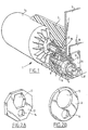
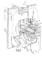
- FIG. 1 Shown in figure 1 is a part of a sawing machine 1 which comprises a housing 2 and a guard cover 3 of the saw blade (not shown in the drawing).
- housing 2 Arranged in housing 2 is an electric motor 4 which is provided with an output shaft 5 which is mounted in housing 2 in a bearing 6 suitable for absorbing radial forces.
- a second shaft 7 is further mounted in housing 2 by means of a bearing 8 and a bearing 9.
- the output motor shaft 5 is provided on its end with a toothing 10, while a tooth wheel 11 is arranged on the second shaft 7. Both tooth wheels 10,11 are in mutual engagement, thus forming a transmission.
- a confining plate 12 is arranged in the motor housing.
- This confining plate 12 is shown in figure 2A.
- the confining plate 12 serves to absorb radial forces between the two shafts 5,7 and thus between the two bearings 6,8.
- holes 13 respectively 14 are arranged in the confining plate 12. It is pointed out here that the confining plate 12 has no further connection to any structural components inside the sawing machine construction; for its function the confining plate 12 is sufficiently enclosed on all sides by the material of the motor housing.
- the confining plate 12 As shown in figure 2A, it is possible to provide the confining plate 12 with a polygonal periphery and polygonal holes.
- the confing plate 12 shown in figure 2B has a round periphery and is provided with round holes.
- Polygonal holes are of course only applicable if the periphery of the bearings arranged therein is form-fitting. Both forms can be combined at random.
- the locking plate 12 must of course be manufactured from sturdy material, for instance a metal. This provides the possibility of manufacturing the housing of a relatively softer material, for instance a plastic.
- the locking plate will have to be connected to the environment via a small heat resistance, for instance by providing the locking plate with ribs or protrusions extending up to the outer wall of the machine. It is also possible to arrange air channels to the locking plate.
- Figure 1 further shows how the bearing 9 of the second shaft is received in an extension 15 formed against the guard cover 3. This bearing is also not further connected to structural components of the circular saw construction.
- a closing plate 16 which is fixed onto bulge 15 by means of bolts 17.
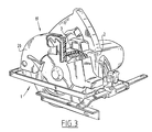
- FIG 3 shows another embodiment of a circular saw machine according to the invention
- the housing 2 of the sawing machine forms one whole, possibly containing various components, with the inner wall 3 of the fixed guard cover 19.
- the latter is otherwise formed by a component 20, which forms the outer side wall, and the jacket wall of the guard cover.
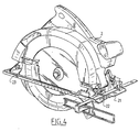
- Figure 4 shows yet another embodiment; this embodiment of the circular sawing machine is provided with a footplate 21 which is connected rotatably by means of hinges 22,23 to the housing 2 of the circular sawing machine.
- the shaft connecting hinges 22 and 23 extends parallel to the saw blade, which enables tilting of sawing machine 2 such that mitre-sawing is thereby possible.
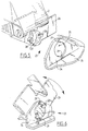
- Hinges 22,23 are shown in more detail in figures 5 and 6.
- the hinge 23 shown in figure 5 is thus formed by a bent part 24 of footplate 21 in which a substantially round hole 25 is made.
- the housing 2 of the circular sawing machine is further connected to a plate 26 extending parallel to the bent part 24 of plate 21, wherein a bulge 27 is arranged in plate 26, for instance by a press. Bulge 27 fits into hole 25, this such that bulge 27 can rotate inside hole 25 and the plate 26 can thus rotate relative to plate part 24.
- footplate 21 can rotate relative to housing 2.
- a bayonet fitting is arranged in the form of punched-out ears 28 which fit into broadened portions 29 of hole 25 arranged for this purpose. It is otherwise also possible to make use of only a single ear.
- plates 26 In order to enable assembly hereof the plates 26 must first be placed in their correct position in relation to plates 24, whereafter housing 2 or optional other components for arranging therebetween must be placed in their position and connected fixedly to plates 26.
- FIG. 6 shows the hinge 23 in its assembled situation. This also illustrates the bayonet action of the diverse components.
- the hinge construction is developed further in the construction shown in figure 7.
- the footplate 21 is herein provided with a bent calibration plate 30, while plate 26 is provided with an elongation in the form of an indicator 31.
- the latter is herein bent round on the outside of calibration plate 30 so that a bent portion 32 is formed.
- a slot 33 is further arranged in calibration plate 30, while both in indicator 31 and in the bent portion 32 thereof is arranged a hole, not shown in the drawing, through which extends a bolt 34.
- Bolt 34 is provided with a wing nut 35.
- the calibration plate 30 is further provided with a calibration 36, while indicator 31 is provided with an arrow tip 37.
- Figure 8 shows another embodiment, wherein the indicator 31 is not bent round but wherein calibration plate 30 is provided with a bent piece 38. It will be apparent that both calibration plate 30 and the bent portion 38 thereof are provided with a slot 33 and that bolt 34 extends through both these latter components. The operation of this embodiment is otherwise the same as that of the foregoing embodiment.
- figure 9 shows by analogy with the embodiment shown in figure 1 a slightly different embodiment of the mounting of bearing 9 in the bulge 15.
- the closing plate 16 here also extends slightly radially relative to bearing 9 so that bearing 9 is also confined in radial direction.
- the closing plate 16, which in this case takes rather the form of a ring, is here also used to confine the movable guard cover 18.
Landscapes
- Life Sciences & Earth Sciences (AREA)
- Engineering & Computer Science (AREA)
- Mechanical Engineering (AREA)
- Wood Science & Technology (AREA)
- Forests & Forestry (AREA)
- Power Engineering (AREA)
- Sawing (AREA)
Claims (15)
- Elektrische Handwerkzeugmaschine (1) mit einem aus einem ersten Material, zum Beispiel Kunststoff, hergestellten Gehäuse (2), einer ersten Welle (5), die in wenigstens einem ersten Lager (6) montiert ist, und einer zweiten Welle (7), die sich parallel zur ersten Welle (5) erstreckt und die mit der ersten Welle (5) mittels einer Kraftübertragung (10, 11) gekoppelt ist und die in wenigstens einem zweiten Lager (8) montiert ist, wobei beide Lager (6, 8) von einer Ebene geschnitten werden, die sich senkrecht zu den Wellen (5, 7) erstreckt, wobei ein Teil (12) vorgesehen ist, das aus einem zweiten Material hergestellt ist, welches fester als das erste Material ist, und das Teil (12) derart angeordnet ist, dass es sich senkrecht zu den Wellen erstreckt und das erste und das zweite Lager (6, 8) diese wenigstens teilweise umschließend wenigstens in Radialrichtung festlegt,
dadurch gekennzeichnet, dass das Teil eine Platte (12) ist, dass das erste und das zweite Lager (6,8) von der Platte (12) vorstehen, und dass das Festlegen der Platte (12) nur durch Kontakt mit dem Gehäuse (2) stattfindet. - Elektrische Handwerkzeugmaschine (1) gemäß Anspruch 1, dadurch gekennzeichnet, dass die erste Welle von der Motorwelle (5) gebildet wird, und dass die zweite Welle eine Antriebswelle (7) ist, von der ein Werkzeug angetrieben ist, das Bestandteil der Werkzeugmaschine (1) ist.
- Elektrische Handwerkzeugmaschine gemäß Anspruch 2, wobei das Werkzeug eine Kreissäge ist, die mit wenigstens einer festgelegten Schutzabdeckung (19) versehen ist, wobei die festgelegte Schutzabdeckung eine sich parallel zum Sägeblatt erstreckende Innenwand (3), eine Verkleidungswand und eine sich parallel zum Sägeblatt erstreckende Außenwand aufweist, dadurch gekennzeichnet, dass wenigstens die Innenwand (3) einstückig mit dem Gehäuse (2) ausgebildet ist.
- Elektrische Kreissäge gemäß Anspruch 3, dadurch gekennzeichnet, dass die Verkleidungswand und die Innenwand der Schutzabdeckung zusammen mit dem Gehäuse einstückig ausgebildet sind.
- Elektrische Kreissäge gemäß Anspruch 3, dadurch gekennzeichnet, dass die verbleibenden Wände der Abdeckung aus einer einstückigen Einheit gebildet werden.
- Elektrische Sägemaschine gemäß Anspruch 2, 3, 4 oder 5, wobei die Sägemaschine eine gelenkig mit dem Gehäuse (2) verbundene Fußplatte (21) aufweist, dadurch gekennzeichnet, dass die Fußplatte mittels wenigstens zweier Gelenke (22, 23) mit dem Gehäuse verbunden ist, und dass jedes Gelenk eine erste Platte (24), die sich senkrecht zum Gelenkbolzen erstreckt und mit der Fußplatte verbunden ist, und eine zweite Platte (26) aufweist, die sich parallel zur ersten Platte (24) erstreckt und mit dem Gehäuse verbunden ist, wobei ein im Wesentlichen rundes Loch (25) in der ersten oder in der zweiten Platte vorgesehen ist und eine sich in das Loch einpassende Sicke (27) in der anderen Platte vorgesehen ist, wobei sich die Sicke in das Loch hineinerstreckt und von den Rändern des Lochs umschlossen ist.
- Elektrische Sägemaschine gemäß Anspruch 6, dadurch gekennzeichnet, dass wenigstens eines der Gelenke mit einem Bajonett-Anschlussstück (28) versehen ist.
- Elektrische Sägemaschine gemäß Anspruch 6 oder 7, dadurch gekennzeichnet, dass die beiden Gelenke zueinander spiegelbildlich angeordnet sind.
- Elektrische Sägemaschine gemäß Anspruch 8, dadurch gekennzeichnet, dass die inneren Platten mit einem Bauteil verbunden sind, das sich wenigstens teilweise zwischen den Platten erstreckt.
- Elektrische Sägemaschine gemäß einem der Ansprüche 2 bis 9, dadurch gekennzeichnet, dass die Fußplatte (21) eine Kalibrierplatte (30) aufweist, die sich senkrecht zur Drehwelle erstreckt, dass das Gehäuse mit einer Anzeigevorrichtung (31) gekoppelt ist, die sich parallel zur und in der Nähe der Kalibrierplatte erstreckt, und dass die Anzeigevorrichtung mit einem Feststellelement versehen ist, mit dem die Anzeigevorrichtung bezüglich der Kalibrierplatte feststellbar ist.
- Elektrische Sägemaschine gemäß Anspruch 10, dadurch gekennzeichnet, dass wenigstens die Kalibrierplatte (30) oder die Anzeigevorrichtung (31) mit einem Abschnitt versehen sind, der sich auf der anderen Seite des anderen Abschnitts erstreckt, um die reibungserzeugende Oberfläche zwischen der Kalibrierplatte und der Anzeigevorrichtung an der Position des Feststellelements zu erhöhen.
- Elektrische Sägemaschine gemäß Anspruch 11, dadurch gekennzeichnet, dass der sich auf der anderen Seite des anderen Abschnitts erstreckende Abschnitt herumgebogen ist.
- Elektrische Sägemaschine gemäß einem der Ansprüche 2 bis 12, dadurch gekennzeichnet, dass die Sägeblattwelle (7) wenigstens in einem Lager (9) montiert ist, welches in einer Verlängerung (15) der Gehäusewand zum Sägeblatt angrenzend angeordnet ist, und dass um die Verlängerung herum ein Verstärkungsring (16) angeordnet ist, der aus einem Material hergestellt ist, welches fester als das Material ist, aus dem das Gehäuse hergestellt ist.
- Elektrische Sägemaschine gemäß Anspruch 13, dadurch gekennzeichnet, dass die Sägemaschine mit einer beweglichen Schutzabdeckung (18) versehen ist, die an der Verlängerung (15) montiert ist.
- Elektrische Sägemaschine gemäß Anspruch 14, dadurch gekennzeichnet, dass die bewegliche Schutzabdeckung (18) von dem Verstärkungsring (16) gehalten wird.
Applications Claiming Priority (2)
| Application Number | Priority Date | Filing Date | Title |
|---|---|---|---|
| NL1001299A NL1001299C2 (nl) | 1995-09-26 | 1995-09-26 | Verbeterde cirkelzaag. |
| NL1001299 | 1995-09-26 |
Publications (2)
| Publication Number | Publication Date |
|---|---|
| EP0765716A1 EP0765716A1 (de) | 1997-04-02 |
| EP0765716B1 true EP0765716B1 (de) | 2002-03-13 |
Family
ID=19761636
Family Applications (1)
| Application Number | Title | Priority Date | Filing Date |
|---|---|---|---|
| EP96202681A Expired - Lifetime EP0765716B1 (de) | 1995-09-26 | 1996-09-25 | Verbesserte Kreissäge |
Country Status (4)
| Country | Link |
|---|---|
| US (1) | US5933969A (de) |
| EP (1) | EP0765716B1 (de) |
| DE (1) | DE69619756T2 (de) |
| NL (1) | NL1001299C2 (de) |
Families Citing this family (16)
| Publication number | Priority date | Publication date | Assignee | Title |
|---|---|---|---|---|
| DE29803006U1 (de) * | 1998-02-20 | 1999-06-24 | Powertools International GmbH, 25474 Ellerbek | Trenngerät |
| DE19844807A1 (de) * | 1998-09-30 | 2000-04-13 | Bosch Gmbh Robert | Motorgetriebene Handwerkzeugmaschine für Trennarbeiten, insbesondere Handkreissäge |
| USD461695S1 (en) | 2001-04-06 | 2002-08-20 | Black & Decker Inc. | Circular saw guard |
| US8695224B2 (en) * | 2007-09-13 | 2014-04-15 | Black & Decker Inc. | Saw with increased depth of cut |
| WO2009064925A1 (en) | 2007-11-13 | 2009-05-22 | Orthopediatrics, Llc | Cast removal system |
| WO2012117870A1 (ja) * | 2011-02-28 | 2012-09-07 | 株式会社マキタ | 切断工具 |
| JP5826526B2 (ja) * | 2011-06-08 | 2015-12-02 | 株式会社マキタ | 電動工具 |
| DE102012005444A1 (de) * | 2012-03-20 | 2013-09-26 | Festool Group Gmbh & Co. Kg | Hand-Werkzeugmaschine |
| EP3765226B1 (de) | 2018-03-16 | 2023-11-01 | Milwaukee Electric Tool Corporation | Klingenklemme für elektrowerkzeug, hin- und herbewegbares kraftwerkzeug und verfahren zum betrieb einer solchen klingenklemme |
| WO2019194987A1 (en) | 2018-04-03 | 2019-10-10 | Milwaukee Electric Tool Corporation | Jigsaw |
| USD887806S1 (en) | 2018-04-03 | 2020-06-23 | Milwaukee Electric Tool Corporation | Jigsaw |
| US10875109B1 (en) | 2018-04-30 | 2020-12-29 | Kreg Enterprises, Inc. | Adaptive cutting system |
| US12263615B2 (en) | 2020-11-23 | 2025-04-01 | Milwaukee Electric Tool Corporation | Circular saw |
| US12465982B2 (en) | 2022-02-24 | 2025-11-11 | Techtronic Cordless Gp | Track saw including plunge lockout mechanism |
| CN223264879U (zh) | 2022-03-18 | 2025-08-26 | 米沃奇电动工具公司 | 圆锯及被配置为在工件中进行切割的轨道锯组件 |
| US12083613B2 (en) | 2022-10-18 | 2024-09-10 | Techtronic Cordless Gp | Track saw including plunge lockout mechanism |
Citations (2)
| Publication number | Priority date | Publication date | Assignee | Title |
|---|---|---|---|---|
| GB1262739A (en) * | 1968-08-09 | 1972-02-02 | Rockwell Mfg Co | Electrically powered hand tool |
| US4589208A (en) * | 1983-08-13 | 1986-05-20 | Matsushita Electric Works, Ltd. | Portable electric circular saw |
Family Cites Families (8)
| Publication number | Priority date | Publication date | Assignee | Title |
|---|---|---|---|---|
| DE743056C (de) * | 1942-03-28 | 1943-12-17 | Festo Maschf Stoll G | Handkreissaege |
| JPS5078998A (de) * | 1973-11-15 | 1975-06-27 | ||
| SE8404998L (sv) * | 1984-10-05 | 1986-04-06 | Electrolux Ab | Motorsagsunderrede |
| DE3505041A1 (de) * | 1985-02-14 | 1986-08-14 | Licentia Patent-Verwaltungs-Gmbh, 6000 Frankfurt | Handkreissaege oder dergleichen elektrowerkzeug mit einem zweischalig ausgebildeten motor- und getriebegehaeuse |
| DE3536464A1 (de) * | 1985-10-12 | 1987-04-16 | Licentia Gmbh | Elektrowerkzeug mit in einem kunststoffgehaeuse gelagerten antriebsmotor |
| NL8801466A (nl) * | 1988-06-07 | 1990-01-02 | Emerson Electric Co | Inrichting voor het aandrijven van een boor- en/of slaggereedschap. |
| US5010651A (en) * | 1990-07-10 | 1991-04-30 | Skil Corporation | Portable circular saw |
| NL9201369A (nl) * | 1992-07-29 | 1994-02-16 | Emerson Electric Co | Elektrisch handgereedschap met reciprocerende aandrijving. |
-
1995
- 1995-09-26 NL NL1001299A patent/NL1001299C2/nl not_active IP Right Cessation
-
1996
- 1996-09-25 US US08/719,573 patent/US5933969A/en not_active Expired - Fee Related
- 1996-09-25 EP EP96202681A patent/EP0765716B1/de not_active Expired - Lifetime
- 1996-09-25 DE DE69619756T patent/DE69619756T2/de not_active Expired - Fee Related
Patent Citations (2)
| Publication number | Priority date | Publication date | Assignee | Title |
|---|---|---|---|---|
| GB1262739A (en) * | 1968-08-09 | 1972-02-02 | Rockwell Mfg Co | Electrically powered hand tool |
| US4589208A (en) * | 1983-08-13 | 1986-05-20 | Matsushita Electric Works, Ltd. | Portable electric circular saw |
Also Published As
| Publication number | Publication date |
|---|---|
| NL1001299C2 (nl) | 1997-03-28 |
| US5933969A (en) | 1999-08-10 |
| EP0765716A1 (de) | 1997-04-02 |
| DE69619756D1 (de) | 2002-04-18 |
| DE69619756T2 (de) | 2002-10-10 |
Similar Documents
| Publication | Publication Date | Title |
|---|---|---|
| US5933969A (en) | Circular saw | |
| JP3542819B2 (ja) | 歯車装置 | |
| US4506559A (en) | Split pulley | |
| KR101441556B1 (ko) | 모터 차량 시트의 조절 장치를 위한 조절 구동 장치 | |
| US5152631A (en) | Positive-engaging coupling for a portable handheld tool | |
| US6628026B2 (en) | Geared motor including ribbed gear housing | |
| FR2712372A1 (fr) | Dispositif de fixation de moteur. | |
| US20230272840A1 (en) | Transmission housing, gearbox and wheeled vehicle provided with such a gearbox | |
| JP2000042829A (ja) | 手動電動工具 | |
| GB2282080A (en) | Steering mechanism for a vehicle toy. | |
| WO1999018369A1 (en) | A drum motor | |
| EP1279828B1 (de) | Nachgiebige Kupplung zur Verbindung des Rotors einer elektischen Maschine mit der Kurbelwelle des Verbrennungsmotors eines Kraftfahrzeugs | |
| EP1914436B1 (de) | Bremsmechanismus | |
| JP2005168339A (ja) | 携帯型作業機 | |
| JP4078761B2 (ja) | 動力伝達装置 | |
| US20020047376A1 (en) | Motor device and transmission mechanism | |
| WO1995028578A1 (fr) | Volant amortisseur, notamment pour vehicule automobile | |
| JP3845952B2 (ja) | 回転電機 | |
| KR200168405Y1 (ko) | 모빌랙의 핸들부고정장치 | |
| JP3294133B2 (ja) | 苗植付機構 | |
| KR100193941B1 (ko) | 전동기의 회전자 조립구조 | |
| EP0754276A1 (de) | Doppelschwungrad-torsionsdämpfer,insbesondere für ein kraftfahrzeug | |
| FR2839758A1 (fr) | Dispositif d'accouplement elastique entre le rotor d'une machine electrique et l'arbre vilebrequin d'un moteur a combustion interne | |
| JP3135023B2 (ja) | 横流ファンの駆動側端板 | |
| KR200153777Y1 (ko) | 팬 조립체 |
Legal Events
| Date | Code | Title | Description |
|---|---|---|---|
| PUAI | Public reference made under article 153(3) epc to a published international application that has entered the european phase |
Free format text: ORIGINAL CODE: 0009012 |
|
| AK | Designated contracting states |
Kind code of ref document: A1 Designated state(s): DE FR GB IT NL |
|
| 17P | Request for examination filed |
Effective date: 19970925 |
|
| 17Q | First examination report despatched |
Effective date: 19990428 |
|
| GRAG | Despatch of communication of intention to grant |
Free format text: ORIGINAL CODE: EPIDOS AGRA |
|
| GRAG | Despatch of communication of intention to grant |
Free format text: ORIGINAL CODE: EPIDOS AGRA |
|
| GRAH | Despatch of communication of intention to grant a patent |
Free format text: ORIGINAL CODE: EPIDOS IGRA |
|
| GRAH | Despatch of communication of intention to grant a patent |
Free format text: ORIGINAL CODE: EPIDOS IGRA |
|
| REG | Reference to a national code |
Ref country code: GB Ref legal event code: IF02 |
|
| GRAA | (expected) grant |
Free format text: ORIGINAL CODE: 0009210 |
|
| AK | Designated contracting states |
Kind code of ref document: B1 Designated state(s): DE FR GB IT NL |
|
| PG25 | Lapsed in a contracting state [announced via postgrant information from national office to epo] |
Ref country code: NL Free format text: LAPSE BECAUSE OF FAILURE TO SUBMIT A TRANSLATION OF THE DESCRIPTION OR TO PAY THE FEE WITHIN THE PRESCRIBED TIME-LIMIT Effective date: 20020313 Ref country code: IT Free format text: LAPSE BECAUSE OF FAILURE TO SUBMIT A TRANSLATION OF THE DESCRIPTION OR TO PAY THE FEE WITHIN THE PRESCRIBED TIME-LIMIT;WARNING: LAPSES OF ITALIAN PATENTS WITH EFFECTIVE DATE BEFORE 2007 MAY HAVE OCCURRED AT ANY TIME BEFORE 2007. THE CORRECT EFFECTIVE DATE MAY BE DIFFERENT FROM THE ONE RECORDED. Effective date: 20020313 |
|
| REF | Corresponds to: |
Ref document number: 69619756 Country of ref document: DE Date of ref document: 20020418 |
|
| ET | Fr: translation filed | ||
| NLV1 | Nl: lapsed or annulled due to failure to fulfill the requirements of art. 29p and 29m of the patents act | ||
| PLBE | No opposition filed within time limit |
Free format text: ORIGINAL CODE: 0009261 |
|
| STAA | Information on the status of an ep patent application or granted ep patent |
Free format text: STATUS: NO OPPOSITION FILED WITHIN TIME LIMIT |
|
| 26N | No opposition filed |
Effective date: 20021216 |
|
| PGFP | Annual fee paid to national office [announced via postgrant information from national office to epo] |
Ref country code: GB Payment date: 20060921 Year of fee payment: 11 |
|
| PGFP | Annual fee paid to national office [announced via postgrant information from national office to epo] |
Ref country code: DE Payment date: 20060929 Year of fee payment: 11 |
|
| GBPC | Gb: european patent ceased through non-payment of renewal fee |
Effective date: 20070925 |
|
| PG25 | Lapsed in a contracting state [announced via postgrant information from national office to epo] |
Ref country code: DE Free format text: LAPSE BECAUSE OF NON-PAYMENT OF DUE FEES Effective date: 20080401 |
|
| REG | Reference to a national code |
Ref country code: FR Ref legal event code: ST Effective date: 20080531 |
|
| PG25 | Lapsed in a contracting state [announced via postgrant information from national office to epo] |
Ref country code: FR Free format text: LAPSE BECAUSE OF NON-PAYMENT OF DUE FEES Effective date: 20071001 |
|
| PGFP | Annual fee paid to national office [announced via postgrant information from national office to epo] |
Ref country code: FR Payment date: 20060927 Year of fee payment: 11 |
|
| PG25 | Lapsed in a contracting state [announced via postgrant information from national office to epo] |
Ref country code: GB Free format text: LAPSE BECAUSE OF NON-PAYMENT OF DUE FEES Effective date: 20070925 |