EP0765717A1 - Ciseaux du type a lames interchangeables - Google Patents
Ciseaux du type a lames interchangeables Download PDFInfo
- Publication number
- EP0765717A1 EP0765717A1 EP96908348A EP96908348A EP0765717A1 EP 0765717 A1 EP0765717 A1 EP 0765717A1 EP 96908348 A EP96908348 A EP 96908348A EP 96908348 A EP96908348 A EP 96908348A EP 0765717 A1 EP0765717 A1 EP 0765717A1
- Authority
- EP
- European Patent Office
- Prior art keywords
- blade
- protruding
- pair
- overlapping
- handle
- Prior art date
- Legal status (The legal status is an assumption and is not a legal conclusion. Google has not performed a legal analysis and makes no representation as to the accuracy of the status listed.)
- Withdrawn
Links
Images


Classifications
-
- B—PERFORMING OPERATIONS; TRANSPORTING
- B26—HAND CUTTING TOOLS; CUTTING; SEVERING
- B26B—HAND-HELD CUTTING TOOLS NOT OTHERWISE PROVIDED FOR
- B26B13/00—Hand shears; Scissors
- B26B13/04—Hand shears; Scissors with detachable blades
-
- B—PERFORMING OPERATIONS; TRANSPORTING
- B26—HAND CUTTING TOOLS; CUTTING; SEVERING
- B26B—HAND-HELD CUTTING TOOLS NOT OTHERWISE PROVIDED FOR
- B26B13/00—Hand shears; Scissors
- B26B13/28—Joints
Definitions
- the present invention relates to a pair of scissors of a replaceable blade type in which a blade portion is replaceable with respect to a handle portion.
- FIG.1 A pair of conventional, general scissors is shown in FIG.1 which is used by a hairdresser or beautician.
- the pair of scissors 1' comprises a movable blade 2' and a stable blade 3', the movable blade 2' having a circular aperture 4', the stable blade 3' having a square aperture 5'.
- the movable blade 2' and the stable blade 3' are pivotally coupled to each other by using an adjust screw 6' and a nut 7'.
- the adjust screw 6' comprises a cylindrical portion 8' and a prismatic portion 9', the cylindrical portion 8' being inserted into the circular aperture 4' of the movable blade 2', the prismatic portion 9' being inserted into the square aperture 5' of the stable blade 3'.
- the stable blade 3' is placed on the hair and the movable blade 2' is pivoted about the adjust screw 6' while contact area 10' works as a fulcrum of leverage; the hair is cut by continuously clenching the blades 11' and 11'' from a root of the blade without an opening.
- the present invention is characterized in that, in a pair of replaceable blade type scissors in which a handle portion and a blade portion are freely connectable and disconnectable, a plurality of fitting apertures are provided in one of the overlapping portions of the handle portion and the blade portion, a plurality of protruding members are provided to the other overlapping portion, and the plurality of the fitting apertures and the plurality of the protruding members are fitted, respectively, so that the handle portion and the blade portion are coupled to each other. Since the fitting apertures and the elastically deformable protruding members are tightly fitted at a plurality of separate positions, unsteadiness between the handle portion and the blade portion is positively prevented.
- the protruding member comprises a small diameter cylindrical portion with a flange and a large diameter cylindrical portion with a flange, the large diameter being press fitted into the overlapping portion, the large diameter cylindrical portion being press fit in the fitting aperture, both a removal of the protruding member from the overlapping portion and a removal of the fitting aperture from the protruding member can be positively prevented. Further, when a slit groove or a cavity opening is provided to the large diameter cylindrical portion of the protruding member, an elastic deformation of the large diameter cylindrical portion is easier, and the fitting to the fitting aperture becomes easier.
- the present invention is characterized in that, in a pair of replaceable blade type scissors in which a handle and a blade portion are freely connectable and disconnectable, a groove portion is provided to one of the overlapping portions of the handle portion and the blade portion, a protruding portion is provided to the other overlapping portion which is fitted in the groove portion, an elastic member is provided between one side of the protruding portion and one side of the groove portion, and the other side of the protruding portion and the other side of the other overlapping portion are pressed against the other side of the groove portion so that the handle portion and the blade portion are coupled to each other.
- the other side of the protruding portion and the other side of the overlapping portion are pressed against the other side of the groove portion by a spring member, a deflection between the handle portion and the blade portion can be surely prevented. Since the other side becomes a reference for positioning due to the pressing of the elastic member, machining accuracy for the protruding portion, the overlapping portion and the groove portion is not necessarily increased so much. Additionally, when the blade portion is replaced relative to the handle portion, the protruding portion on one of the overlapping portions is inserted into the groove portion in the other one of overlapping portions and the elastic member is inserted therebetween, and thus the replacing operation is very easy.
- the protruding portion has a stepwise shape, and if an engaging portion, which is engaged with an end portion of the elastic member, is provided to one of the groove portion and the protruding portion, the elastic member can be surely and easily mounted in a predetermined position.
- FIG.1 is an exploded perspective view of a pair of conventional scissors.
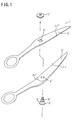
- FIG.2 is an exploded perspective view of a movable blade of a pair of replaceable blade type scissors according to a first embodiment of the present invention.
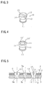
- FIG.3 is a perspective view of a protruding member in the first embodiment.
- FIG.4 is a perspective view of the protruding member in a variation.
- FIG.5 is a cross-sectional view of a coupling portion between a blade portion and a handle portion in the first embodiment.
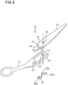
- FIG.6 is an exploded perspective view of a movable blade of a pair of replaceable blade type scissors according to a second embodiment of the present invention.
- FIG.7 is a plan view of the movable blade in the second embodiment.
- FIG.8 is a plan view of the movable blade in a variation.
- FIGS.2-8, A description will now be given, with reference to FIGS.2-8, of an embodiment of a pair of replaceable blade type scissors according to the present invention.
- FIG.2 shows a movable blade 1 of the pair of replaceable blade type scissors according to a first embodiment.
- the movable blade 1 and a stable blade has substantially the same configuration except for the configuration (refer to FIG.1) of apertures into which an adjust screw is inserted, and thus illustrations and descriptions of the stable blade is omitted.
- a handle portion 2 and a blade portion 3 are freely connectable and disconnectable, and an overlapping portion 4 of the handle portion 2 and an overlapping portion 9 of the blade portion 3 are coupled to each other.
- the overlapping portion 4 of the handle portion 2 is provided with a pair of spaced fitting apertures 5 having a circular shape.
- a circular aperture 7a as a shaft insertion aperture into which a cylindrical portion 6a of the adjust screw 6, which is a pivot shaft, is fitted. That is, the center of each of the fitting apertures 5 and the center of the circular aperture 7a are arranged on a straight line, and distances between the circular aperture 7a and each of the pair of the fitting apertures 5 are the same.
- a pair of spaced protruding members 10 corresponding to the above-mentioned fitting apertures 5.
- a circular aperture 7b corresponding to the above-mentioned circular aperture 7a, into which a cylindrical portion 6a of the adjust screw 6 is inserted. That is, the center of each of the pair of protruding members 10 and the center of the circular aperture 7b are arranged on a straight line, and distances between the circular aperture 7b and each of the pair of the protruding members 10 are the same.
- the protruding member 10 comprises a small diameter cylindrical portion 12 having a flange 11 and a large diameter cylindrical portion 14 having a flange 13, the large diameter cylindrical portion 14 being provided with the a slit groove 15 extending in a diametral direction.
- the protruding member 10 is integrally formed of an elastically deformable material such as, for example, synthetic resin, and especially the elastic deformation of the large diameter cylindrical portion 14 is facilitated by the slit groove 15.
- a protruding member 10' shown in FIG.4 is provided with a cavity 15' formed in the large diameter cylindrical portion 14 instead of the slit groove 15 of the large diameter cylindrical portion 14. Since the large diameter cylindrical portion 14 has a ring shape due to the cavity 15', the elastic deformation is facilitated. It should be noted that other structures are substantially the same as that of the example shown in FIG.3.
- the small diameter cylindrical portion 12 of the protruding member 10 is press fitted into a circular aperture 9a provided in the overlapping portion 9 of the blade portion 3, and is prevented from being removed due to the flange 11 and the large diameter cylindrical portion 14. Since the protruding members 10 are elastically deformable, the fixed state of the protruding member 10 against the overlapping portion 9 is very reliable due to a tight contact by the press fitting. It should be noted that the protruding members 10 may be previously press fit to the overlapping portion 9, or may be press fit at the time of use.
- the overlapping portion 4 is forcibly pressed against the overlapping portion 9 while both the fitting apertures 5 of the handle portion in the handle portion 2 are opposed to both the protruding members 10 of the overlapping portion 9 in the blade portion 3.
- both the fitting apertures 5 are fitted to the large diameter cylindrical portions 14 of both the protruding members 10, and the overlapping portion 4 of the handle portion 2 and the overlapping portion 9 of the blade portion are tightly coupled.
- the large diameter cylindrical portion 14 of the protruding member 10 is elastically deformable due to the slit groove 15, the fitting of the large diameter cylindrical portion 14 to the fitting aperture 5 is easy, and after the fitting, removal from the fitting aperture 5 is prevented by the elastic restoration of the large diameter cylindrical portion 14 and the flange 13.
- the movable blade 1, in which the handle portion 2 and the blade portion 3 are coupled is pivotally coupled with the stable blade, in which a handle portion and a blade portion are coupled in a similar manner but not shown in the figures, by using the adjust screw 6 and the nut 8, and the assembly of the replaceable blade type scissors is completed.
- a cylindrical portion 6a of the adjust screw 6 is inserted into the circular apertures 7a and 7b of the movable blade 1, and a prismatic portion 6b is inserted into the square aperture of the stable blade.
- connection between the handle portion 2 and the blade portion 3 is possible by rendering the number of fitting apertures 5 and the protruding members 10 to be more than three or rendering the circular apertures 7a and 7b to be offset from both the fitting apertures 5 and both the protruding members 10.
- pairs are formed by the fitting apertures 5 and protruding members 10, and when the circular apertures 7a and 7b are positioned between both the fitting apertures 15 and both the protruding members 10 as is in the present embodiment, the centers of these parts are aligned in a straight line, and thus the centering of the handle portion 2 and blade portion 3 becomes easy.
- FIG.6 shows a movable blade 20 of a pair of replaceable blade type scissors according to a second embodiment. It should be noted that illustrations and descriptions of a stable blade are omitted for the same reason mentioned above.
- a handle portion 21 and a blade portion 22 are freely connectable and disconnectable, and an overlapping portion 23 of the handle portion 21 and an overlapping portion 27 of blade portion 22 are coupled to each other.
- a groove portion 24 is formed in the overlapping portion 23 of the handle portion 21.
- a circular aperture 25 for the adjust screw is provided in the groove portion 24, and an engaging portion 26 having a generally circular and recessed shape is provided at an inner end of the groove portion 24.
- a stepwise protruding portion 28 is integrally formed with the overlapping portion 27 of the blade portion 22 which is fitted into the above-mentioned groove portion 24.
- a width of the overlapping portion 27 is smaller than a width of the groove portion 24, and a width of the protruding portion 28 is further smaller than the with of the overlapping portion 27.
- the reference numeral 25 indicates a circular aperture for the adjust screw, and 30 indicates a contact area.
- the overlapping portion 27 and the protruding portion 28 are fitted into the groove portion 24; a generally S-shaped plate spring which is an elastic member, that is, an end portion 29a of a spring 29 is engaged within an engaging portion 26; a bent portion 29b of the spring 29 contacts one of the sides of the protruding portion 28 and an opposite end portion 29c contacts one of the sides of the groove portion 24.
- the other side of the protruding member 28 and the overlapping portion 27 is pressed against the other side of the groove portion 24.
- a gap is formed between the one of the sides of the overlapping portion 27 and the one of the sides of the groove portion 24 but the other side of the overlapping portion 27 and the protruding portion 28 makes a surface contact with the other side of the groove portion 24, and deflection of the blade portion 22 with respect to the handle portion 21 is positively prevented. Since there is the gap on the one side but the other side becomes a reference for the positioning due to the pressing of the spring 29, there is no need to substantially increase machining accuracy of the widths of the overlapping portion 27 and the protruding portion 28 with respect to the groove portion 24.
- the protruding portion 28 has the stepwise shape and the end portion 29a of the spring 29 is engaged with the engaging portion 26 provided to the groove portion 24, the spring 29 can be surely and easily mounted in a predetermined position.
- an engaging portion 26' to which the end portion 29a of the spring 29 is engaged, is provided to the protruding portion 28, and the bent potion 29b of the spring 29 contacts a side of the groove portion 24.
- pressing action similar to the above-mentioned arrangement can be achieved. It should be noted that other structures are substantially the same as that shown in FIGS.6 and 7.
- the blade portion is very surely coupled to the handle portion without unsteadiness, sharpness can be maintained by replacing the blade portion, and a pair of replaceable blade type scissors can be provided which has a sufficient performance particularly for professional use by a hairdresser or beautician.
- the replacing operation of the blade portion is very easy, anyone can surely and easily perform the replacing operation of the blade portion, and use is not limited to a hairdresser or beautician but is a replaceable blade type scissors for a wide range of users and purposes.
Landscapes
- Life Sciences & Earth Sciences (AREA)
- Forests & Forestry (AREA)
- Engineering & Computer Science (AREA)
- Mechanical Engineering (AREA)
- Scissors And Nippers (AREA)
Applications Claiming Priority (3)
| Application Number | Priority Date | Filing Date | Title |
|---|---|---|---|
| JP10317495 | 1995-04-05 | ||
| JP103174/95 | 1995-04-05 | ||
| PCT/JP1996/000930 WO1996031326A1 (fr) | 1995-04-05 | 1996-04-05 | Ciseaux du type a lames interchangeables |
Publications (2)
| Publication Number | Publication Date |
|---|---|
| EP0765717A1 true EP0765717A1 (fr) | 1997-04-02 |
| EP0765717A4 EP0765717A4 (fr) | 1999-01-20 |
Family
ID=14347152
Family Applications (1)
| Application Number | Title | Priority Date | Filing Date |
|---|---|---|---|
| EP96908348A Withdrawn EP0765717A4 (fr) | 1995-04-05 | 1996-04-05 | Ciseaux du type a lames interchangeables |
Country Status (4)
| Country | Link |
|---|---|
| EP (1) | EP0765717A4 (fr) |
| KR (1) | KR970703227A (fr) |
| TW (1) | TW343587U (fr) |
| WO (1) | WO1996031326A1 (fr) |
Cited By (2)
| Publication number | Priority date | Publication date | Assignee | Title |
|---|---|---|---|---|
| US20130000131A1 (en) * | 2011-06-30 | 2013-01-03 | Iittala Group Oy Ab. | Cutting tool |
| CN103317532A (zh) * | 2012-03-22 | 2013-09-25 | 孙根岳 | 理发剪具 |
Families Citing this family (2)
| Publication number | Priority date | Publication date | Assignee | Title |
|---|---|---|---|---|
| FR2774935B1 (fr) | 1998-02-19 | 2000-03-17 | Manuf D Articles De Precision | Ciseaux a lames interchangeables |
| DE102012023295A1 (de) * | 2012-11-28 | 2014-05-28 | Mtd Products Inc. | Gartenschere |
Family Cites Families (5)
| Publication number | Priority date | Publication date | Assignee | Title |
|---|---|---|---|---|
| JPS5424196U (fr) * | 1977-07-20 | 1979-02-16 | ||
| JPS56106674A (en) * | 1980-01-22 | 1981-08-25 | Wilkinson Sword Ltd | Portable tool consisting of two mutually cooperating forming section |
| GB2096041A (en) * | 1981-04-08 | 1982-10-13 | Smout Michael Leslie | Cutting implements |
| JPH0712071U (ja) * | 1993-08-03 | 1995-02-28 | 株式会社サンギ | 刃先交換式ハサミ |
| JPH07155480A (ja) * | 1993-12-07 | 1995-06-20 | Kanematsu Kogyo Kk | 刃体交換式はさみ |
-
1996
- 1996-04-05 KR KR1019960706725A patent/KR970703227A/ko not_active Withdrawn
- 1996-04-05 WO PCT/JP1996/000930 patent/WO1996031326A1/fr not_active Ceased
- 1996-04-05 EP EP96908348A patent/EP0765717A4/fr not_active Withdrawn
- 1996-04-29 TW TW087203054U patent/TW343587U/zh unknown
Cited By (3)
| Publication number | Priority date | Publication date | Assignee | Title |
|---|---|---|---|---|
| US20130000131A1 (en) * | 2011-06-30 | 2013-01-03 | Iittala Group Oy Ab. | Cutting tool |
| US9174348B2 (en) * | 2011-06-30 | 2015-11-03 | Fiskars Home Oy Ab | Cutting tool |
| CN103317532A (zh) * | 2012-03-22 | 2013-09-25 | 孙根岳 | 理发剪具 |
Also Published As
| Publication number | Publication date |
|---|---|
| WO1996031326A1 (fr) | 1996-10-10 |
| TW343587U (en) | 1998-10-21 |
| KR970703227A (ko) | 1997-07-03 |
| EP0765717A4 (fr) | 1999-01-20 |
Similar Documents
| Publication | Publication Date | Title |
|---|---|---|
| US8991058B2 (en) | Shaving blade unit and shaver having such a blade unit | |
| US4198750A (en) | Ring blade knife having wear plate | |
| CA1113704A (fr) | Lames de rasoir encastrees | |
| CA1109657A (fr) | Tondeuse de cheveux | |
| EP0838312A2 (fr) | Rasoirs | |
| US20030079348A1 (en) | Razor assembly with replaceable cartridge | |
| US20110232101A1 (en) | Unitary cartridge | |
| EP1273400B1 (fr) | Dispositif de rasage avec des lames statiques et mobiles | |
| US2807084A (en) | Multiple blade safety razor with aligning means | |
| EP0020816A1 (fr) | Rasoir mécanique | |
| KR20210057018A (ko) | 면도기 핸들, 부착 어댑터 및 면도기 조립체 | |
| EP0765717A1 (fr) | Ciseaux du type a lames interchangeables | |
| US4413410A (en) | Electric shaver with rotary blade | |
| WO2022126122A1 (fr) | Outil de rasoir et procédé | |
| US4612708A (en) | Replaceable blade type medical scissors | |
| JPS5946619B2 (ja) | 乾式ひげそり装置のシエ−ビングヘツド | |
| US4754547A (en) | Safety razor | |
| TW200416116A (en) | Snips with removable blades | |
| US3526959A (en) | Dry shavers | |
| JPWO1996031326A1 (ja) | 替え刃式ハサミ | |
| US3651568A (en) | Trimming razor | |
| US2289652A (en) | Shaving machine | |
| EP0020815A1 (fr) | Manche pour rasoir mécanique | |
| US2018042A (en) | Safety razor | |
| US2089283A (en) | Safety razor |
Legal Events
| Date | Code | Title | Description |
|---|---|---|---|
| PUAI | Public reference made under article 153(3) epc to a published international application that has entered the european phase |
Free format text: ORIGINAL CODE: 0009012 |
|
| 17P | Request for examination filed |
Effective date: 19961204 |
|
| AK | Designated contracting states |
Kind code of ref document: A1 Designated state(s): AT DE ES FR GB IT |
|
| A4 | Supplementary search report drawn up and despatched |
Effective date: 19981204 |
|
| AK | Designated contracting states |
Kind code of ref document: A4 Designated state(s): AT DE ES FR GB IT |
|
| STAA | Information on the status of an ep patent application or granted ep patent |
Free format text: STATUS: THE APPLICATION HAS BEEN WITHDRAWN |
|
| 18W | Application withdrawn |
Withdrawal date: 19990114 |