EP0765770B1 - Kupplungsvorrichtung zwischen einem Lastkraftwagen und einem Anhängerwagen mit Wegläufer-Kontrolle für Anhängerwagen - Google Patents
Kupplungsvorrichtung zwischen einem Lastkraftwagen und einem Anhängerwagen mit Wegläufer-Kontrolle für Anhängerwagen Download PDFInfo
- Publication number
- EP0765770B1 EP0765770B1 EP96440075A EP96440075A EP0765770B1 EP 0765770 B1 EP0765770 B1 EP 0765770B1 EP 96440075 A EP96440075 A EP 96440075A EP 96440075 A EP96440075 A EP 96440075A EP 0765770 B1 EP0765770 B1 EP 0765770B1
- Authority
- EP
- European Patent Office
- Prior art keywords
- trailer
- drawbar
- truck
- coupling gear
- mechanical coupling
- Prior art date
- Legal status (The legal status is an assumption and is not a legal conclusion. Google has not performed a legal analysis and makes no representation as to the accuracy of the status listed.)
- Expired - Lifetime
Links
Images





Classifications
-
- B—PERFORMING OPERATIONS; TRANSPORTING
- B60—VEHICLES IN GENERAL
- B60D—VEHICLE CONNECTIONS
- B60D1/00—Traction couplings; Hitches; Draw-gear; Towing devices
- B60D1/14—Draw-gear or towing devices characterised by their type
- B60D1/173—Draw-gear or towing devices characterised by their type consisting of at least two bars which are not connected or articulated to each other
-
- B—PERFORMING OPERATIONS; TRANSPORTING
- B60—VEHICLES IN GENERAL
- B60D—VEHICLE CONNECTIONS
- B60D1/00—Traction couplings; Hitches; Draw-gear; Towing devices
- B60D1/14—Draw-gear or towing devices characterised by their type
- B60D1/145—Draw-gear or towing devices characterised by their type consisting of an elongated single bar or tube
- B60D1/155—Draw-gear or towing devices characterised by their type consisting of an elongated single bar or tube comprising telescopic or foldable parts
Definitions
- the present invention relates to a mechanical coupling between a truck and a trailer, control of the trajectory of the trailer, in accordance with the characteristics of the preamble of claim 1.
- the mechanical coupling according to the invention is formed of a drawbar and at least one oblique connection, rigid, articulated by one of its ends to the trailer and by its other end to the truck.
- the road hitches provide the trailer with clearing trajectory so that it is in a better position in turns and out of curves in order to better follow the road lane which is assigned to the truck-trailer combination.
- This hitch consists of a drawbar and an oblique link articulated on a train interface before director.
- the drawbar is hinged mounted at its front end on the hook towing the truck and at its rear end on the round front end conventionally constituting the interface between the front axle and the hitch.
- the axle front is fixed.
- An intermediate control unit ensures the directional orientation of the front wheels from the direction of the pulling force exerted on the drawbar.
- This invention uses a drawbar, an oblique rod, a control interface and the train front of a trailer known as a steering front axle.
- the oblique connecting rod provides a trajectory cornering cornerer of the trailer on which it is articulated away from the corresponding rear corner of the truck.
- the drawbar does not transmit a significant load to the towing vehicle because the weight of the front part is supported by the steering front axle.
- This coupling is specific to a train trailer before director.
- the object of the present invention is to provide a center axle trailer with these characteristics and ensures a clear path at the corner of the trailer.
- the object of the present invention is to arrive at this result with simple means only mechanical i.e. a drawbar of constant length or a passive and free telescopic drawbar in extension-retraction, that is to say not recalled under the effect of a fluid or the like and one or two oblique rod (s) rigid (s), of constant length, articulated on the trailer and on the truck.
- the invention also aims with a hitch simple mechanics to give the trailer a clearing path which allows the transport of loads protruding from the front of the trailer and / or the back of the truck.
- the invention proposes to achieve these results more specifically with a coupling conforming to the characteristics of claim 1.
- a mechanical coupling formed on the one hand by a drawbar whose front end is hooked at the rear, for example overhanging the truck, and whose the rear end is part of a center of pivoting around a substantially vertical axis mounted on the trailer chassis and on the other hand at minus a connecting rod oblique to the direction of straight line, rigid rod and constant length, articulated climb by one of its ends on the back of the truck and by its other end to the rear of the trailer.
- the link formed by a single oblique link is doubled by a second oblique rod to transform into a link with crossed connecting rods arranged in straight line configuration, along diagonals in the space between the truck and the trailer.
- This invention in its application short hitch brings several advantages additional important including the possibility with a reduced truck-trailer space to place loads indivisible cantilevered and projecting nested from the back of the truck and / or the front of the trailer.
- the present invention relates to a mechanical coupling between a motor vehicle, called here for the sake of simplification truck 1, and a trailer 2.
- Trailer 2 is shown as a center axle trailer 3 and 4 and will be described Such as.
- Truck 1 has a cab 5 and a chassis 6, the latter being surmounted by a bodywork 7 fixed or removable.
- This bodywork is provided by example, but not necessarily, for transporting cars on platforms or platforms individual loading.
- trailer which includes a frame 8 on which is mounted for example a bodywork for 9 car carriers with platforms or individual loading platforms.
- the vehicles, truck and trailer delimit between them an intermediate space for connecting 10 truck-trailer, for example protected by a bellows 11, as shown in Figures 1 and 2.
- the present invention relates to binding between truck and trailer forming a mechanical coupling 12 to control the trajectory of the trailer formed a pivoting drawbar and at least one oblique connection relative to the straight line direction.
- FIGS 1 and 2 show the whole trailer truck with any swivel drawbar 13.
- this pivoting drawbar can be rigid and of constant length in a first mode of realization with a single oblique connection or free and passive telescopic in a second form of double oblique connection.
- the pivoting drawbar 13 has on the one hand a front end 14 connected to a coupling point 15 with hook carried by a transverse mechanical assembly 16 secured to the truck chassis 6 or the bodywork having for example an extension rear cantilever and on the other end rear 17 forming part or constituting one of the parts a pivot center 18 mounted in cantilever at the front of the trailer chassis 8 or in the vicinity of this one.
- the swivel drawbar 13 is a rigid swivel drawbar 19 pivoting around the pivot center 18.
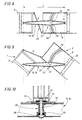
- This drawbar is of constant length L and the oblique bond is constituted by a rigid rod 20 of length D constant. It crosses obliquely the plane longitudinal center line of the vehicle according to a diagonal arrangement and is articulated by its ends level, for example from a rear corner 21 or 22 of the truck and a front corner 23 or 24 of the trailer.
- the center of pivot 18 is made in the form of a round front end 25 mounted in cantilever at the front of the trailer chassis 8.
- a second variant of the first form of realization implements a pivot center 18 equivalent to the front end of the first variant which therefore provides the same effects.
- the round front end 25 is replaced by a pivoting axle end 26 mounted vertically under the chassis 8 trailer in the middle position and perpendicular to it frame.
- the whole is completed by a means of link-support 27 of the trailer at the front.
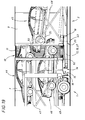
- link-support 27 consists in the example represented in a track 28 in an arc and in a sliding support on this track on a range area 29 formed by the surface of the drawbar opposite the track 28 in an arc completed with a sliding connection 30 between the drawbar and the structure of the track 28 in an arc.
- This link allows maintain the front part of the trailer chassis 8 against the drawbar and thereby preventing movement between the drawbar and the trailer in the case of a load larger at the rear of the trailer.
- This link allows security additional in the event of the axis 26 breaking pivoting.
- connection 30 is made in the form a connecting bolt 32 whose head presses through a flat washer 33 and an anti-friction interlayer 34 against the internal faces of the edges of the track in arc.
- the connecting bolt 32 has a prestress, for example in the form of a 35 effect washer elastic provided at its lower end at the neighborhood of its clamping nut 36.
- track and link assembly assembly can be replaced by equivalent means support-slip.
- the end joints of the connecting rod rigid oblique 20 are of the ball type or pivot joints with degree (s) additional (s) allowing the appropriate travel to absorb roll and pitch movements.
- the connecting rod oblique 20 When operating in curves, the connecting rod oblique 20 pushes or pulls the opposite corner of the trailer constituting for it a bond which imposes on it when cornering a trajectory that fits better in the channel assigned to it, as shown in Figure 3. This characteristic results from the diagonal arrangement of the oblique rod 20.
- center of pivot 18 can be anywhere trailer chassis 8 from the axles to the front of the trailer.
- the swiveling drawbar 13 is a telescopic swiveling drawbar mechanical 37, entirely free and passive, i.e. that he has no active means extension / withdrawal or recall, but also that slides freely without constraint for example without braking or damping force to present different lengths for example L2 between a value minimum L1 and maximum length L3 ( Figures 16 to 18). Furthermore, it is carried out with means simple mechanical. For example, it is a beam hollow in which is slidably fitted another beam forming the bar of the pivoting drawbar 37.
- drawbar 37 pivoting around the pivot center 18 has safety stops designed to limit its acceleration or braking.
- the telescopic pivoting drawbar 37 is completed by a double articulated link 38 with two rigid connecting rods 39 and 40 constituted by the symmetrical addition to the first connecting rod 39 of a second oblique rigid connecting rod 40 articulated by one of its ends at the rear of the truck and by its other end at the front of the trailer.
- These two symmetrical connecting rods called connecting rods crossed 39 and 40 of equal constant length referenced D1 and D2 each extend obliquely and diagonally to the line direction right, from one of the corners 23,24 of the front front 41 of the trailer to one of the corresponding corners 21,22 of the front rear 42 of chassis 6 of the truck.
- the corners specific to the end of the same rod are diagonally opposites.
- These crossed connecting rods are articulated by their ends either directly or by through corner pieces attached to the forehead front 41 of trailer chassis and rear front 42 of the truck chassis.
- the pivot center 18 can also here be anywhere in chassis 8 of trailer from the axles to the front of the trailer.
- Cross rods prevent telescoping opposite corners of the trailer and truck.
- the pivot center 18 is, according to the variants, the front end ring 25 pivoting around a substantially vertical axis 43 ( Figures 1 to 7 and 11 15) or the pivot axis of the drawbar end 26 ( Figures 8 and 9).
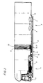
- the front end 25 is cantilevered at the front under the trailer chassis 8. He is trained conventionally of a circular body, integral with the trailer chassis on which a part is mounted cylindrical secured to the end of the pivoting drawbar. The return of the cylindrical part presses on a circular crown of beads.
- Axis 43 of the front end circle is preferably slightly tilted forward of in order to improve the stability of the whole road by rolling.
- drawbar can also be coupled to a removable body carried by the truck and not directly on the truck.
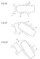
- the invention has the important advantage of allowing transport, cantilevered or projecting in the space between the two vehicles, indivisible charges, for example cars such that 44,45 and 46 carried by individual trays 47,48 and 49 fitted with extensions 50,51 and 52.
Landscapes
- Engineering & Computer Science (AREA)
- Transportation (AREA)
- Mechanical Engineering (AREA)
- Body Structure For Vehicles (AREA)
- Regulating Braking Force (AREA)
- Vehicle Body Suspensions (AREA)
- Control Of Driving Devices And Active Controlling Of Vehicle (AREA)
- Vehicle Cleaning, Maintenance, Repair, Refitting, And Outriggers (AREA)
- Handcart (AREA)
- Agricultural Machines (AREA)
Claims (14)
- Kupplungsvorrichtung mit einem Lastwagen (1) und einem Anhänger (2) sowie einer Verbindung zwischen dem Lastwagen (1) und dem Anhänger (2), die eine Steuerung des Fahrwegs des Anhängers im Sinne eines distanzierenden Fahrwegs ermöglicht, wobei die Verbindung einerseits von einer Deichsel (13), deren vorderes Ende (14) frei schwenkbar am Heck des Lastwagens (1) eingehängt ist und deren hinteres Ende (17) Teil eines am Grundrahmen des Anhängers (2) angeordneten Schwenkzentrums (18) mit einer im wesentlichen vertikalen Achse ist, andererseits von wenigstens einem Schräglenker (20, 39, 40) in diagonaler Stellung mit konstanter Länge gebildet ist, dessen eines Ende an der Front des Anhängers (2) und dessen entgegengesetztes Ende am Heck des Lastwagens (1) angelenkt ist, dadurch gekennzeichnet, daß der Anhänger (2) in seinem im wesentlichen zentralen oder hinteren Bereich ein Fahrwerk mit wenigstens einer Achse (3, 4) aufweist, die den Bereich des Grundrahmens (8) des Anhängers (2) von seinem vorderen Ende bis zur vorderen Achse (3) des Fahrwerks mit wenigstens einer Achse (3, 4) freiläßt, daß das Schwenkzentrum (18) in dem freien Bereich des Grundrahmens (8) des Anhängers (2) in einer vorkragenden Position zwischen der Front des Anhängers (2) und der vorderen Achse (3) des Fahrwerks mit wenigstens einer Achse (3, 4) angeordnet ist, daß zumindest der Schräglenker (20, 39, 40) die Front des Anhängers (2) mit dem Heck des Lastwagens (1) in der diagonalen Position gelenkig verbindet, und daß die Deichsel (13) für Vertikalbewegungen bezüglich des Grundrahmens (8) des Anhängers (2) unbeweglich ist, wobei die aus der Deichsel (13) und dem Schwenkzentrum (18) gebildete Einheit eine ständige Halte- oder Stützverbindung für jede auf den Anhänger (2) wirkende Vertikalkraft oder -last bildet.
- Mechanische Kupplungsvorrichtung nach Anspruch 1, dadurch gekennzeichnet, daß die Kupplungsvorrichtung einen einzigen Schräglenker (20) und eine Deichsel (13) unveränderlicher Länge aufweist.
- Mechanische Kupplungsvorrichtung nach einem der vorangehenden Ansprüche, dadurch gekennzeichnet, daß das Schwenkzentrum (18) ein um eine Achse (43) schwenkbares Rundprofil eines vorderen Drehgestells (25) des Anhängers ist.
- Mechanische Kupplungsvorrichtung nach dem vorangehenden Anspruch, dadurch gekennzeichnet, daß die Schwenkachse (43) schwach nach vorne geneigt ist.
- Mechanische Kupplungsvorrichtung nach einem der Ansprüche 1, 2 oder 3, dadurch gekennzeichnet, daß das Schwenkzentrum (18) eine Schwenkachse (26) am hinteren Ende der schwenkbaren Deichsel (13) ist.
- Mechanische Kupplungsvorrichtung nach dem vorangehenden Anspruch, dadurch gekennzeichnet, daß das Schwenkzentrum (26) durch ein vorderes Stützmittel (27) des Anhängers (2) ergänzt ist.
- Mechanische Kupplungsvorrichtung nach dem vorangehenden Anspruch, dadurch gekennzeichnet, daß das Stützmittel ein Stützverbindungsmittel (27) ist.
- Mechanische Kupplungsvorrichtung nach Anspruch 6 oder 7, dadurch gekennzeichnet, daß das Stütz- oder Stützverbindungsmittel (27) aus einer an dem Anhänger angeordneten kreisbogenförmigen Spur (27) und einem Gleitanschlag der Spur in einem Abstützbereich (29) besteht, der durch die der kreisbogenförmigen Spur (28) zugekehrten Oberfläche der Deichsel (13) gebildet und von einer Gleitverbindungseinheit (30) zwischen der Deichsel (13) und der Struktur der kreisbogenförmigen Spur (28) ergänzt ist, und daß die Gleitverbindungseinheit (30) zwischen der Deichsel (13) und der Struktur der kreisbogenförmigen Spur (28) nach Art eines Verbindungsbolzens (32) gebildet ist, dessen Kopf eine Scheibe (33) und eine Antifriktionszwischenlage (34) durchsetzend den Innenseiten der Ränder der kreisbogenförmigen Spur (28) anliegt, wobei der Verbindungsbolzen (32) eine Vorspannung in Form einer an seinem inneren Ende in der Nähe seiner Spannmutter (36) vorgesehenen elastisch wirkenden Unterlegscheibe (35) bildet.
- Mechanische Kupplungsvorrichtung nach einem der vorangehenden Ansprüche, dadurch gekennzeichnet, daß der einzige Schräglenker durch einen identischen und symmetrischen Schräglenker verdoppelt ist, um eine Verbindung (30) mit zwei überkreuz angeordneten Schräglenkern (39, 40) zu bilden, die bezüglich der Längsmittelachse diagonal angeordnet und auf identische Weise angelenkt sind, und daß die für Vertikalbewegungen unbewegliche, schwenkbare Deichsel eine Teleskopdeichsel (37) ist.
- Mechanische Kupplungsvorrichtung nach dem vorangehenden Anspruch, dadurch gekennzeichnet, daß die schwenkbare Teleskopdeichsel (37) passiv und frei bezüglich Verlängerungs- oder Verkürzungsbewegungen ist.
- Mechanische Kupplungsvorrichtung nach einem der vorangehenden Ansprüche, dadurch gekennzeichnet, daß die Enden des oder der Schräglenker(s) jeweils an einer frontseitigen Ecke (23, 24) des Anhängers und an einer heckseitigen Ecke (21, 22) des Lastwagens angelenkt sind.
- Mechanische Kupplungsvorrichtung nach einem der vorangehenden Ansprüche, dadurch gekennzeichnet, daß die endseitigen Gelenke des oder der Schräglenker(s) nach Art von Kugelgelenken ausgebildet sind.
- Mechanische Kupplungsvorrichtung nach einem der vorangehenden Ansprüche, dadurch gekennzeichnet, daß der Zwischenraum (10) der Verbindung zwischen dem Lastwagen (1) und dem Anhänger (2) durch einen Balg (11) geschützt ist.
- Mechanische Kupplungsvorrichtung nach einem der vorangehenden Ansprüche, dadurch gekennzeichnet, daß der Zwischenraum (10) der Verbindung zwischen dem Lastwagen (1) und dem Anhänger (2) von geringer Länge ist.
Applications Claiming Priority (2)
| Application Number | Priority Date | Filing Date | Title |
|---|---|---|---|
| FR9511586A FR2739326B1 (fr) | 1995-09-28 | 1995-09-28 | Attelage mecanique entre un camion et une remorque avec commande de la trajectoire de la remorque |
| FR9511586 | 1995-09-28 |
Publications (2)
| Publication Number | Publication Date |
|---|---|
| EP0765770A1 EP0765770A1 (de) | 1997-04-02 |
| EP0765770B1 true EP0765770B1 (de) | 2000-11-22 |
Family
ID=9483164
Family Applications (1)
| Application Number | Title | Priority Date | Filing Date |
|---|---|---|---|
| EP96440075A Expired - Lifetime EP0765770B1 (de) | 1995-09-28 | 1996-09-27 | Kupplungsvorrichtung zwischen einem Lastkraftwagen und einem Anhängerwagen mit Wegläufer-Kontrolle für Anhängerwagen |
Country Status (6)
| Country | Link |
|---|---|
| US (1) | US6241270B1 (de) |
| EP (1) | EP0765770B1 (de) |
| AT (1) | ATE197693T1 (de) |
| DE (1) | DE69611022T2 (de) |
| ES (1) | ES2152504T3 (de) |
| FR (1) | FR2739326B1 (de) |
Families Citing this family (5)
| Publication number | Priority date | Publication date | Assignee | Title |
|---|---|---|---|---|
| US8459625B1 (en) * | 2009-03-31 | 2013-06-11 | Honda Motor Co., Ltd. | Device for securing vehicle body to conveyor carrier |
| US8621991B1 (en) | 2010-08-23 | 2014-01-07 | Rodolfo Lopez | Pistol grip spring compressor system and method for maintaining compression on a valve spring |
| RU2503552C1 (ru) * | 2012-06-05 | 2014-01-10 | Федеральное государственное бюджетное образовательное учреждение высшего профессионального образования "Алтайский государственный технический университет им. И.И. Ползунова" (АлтГТУ) | Сцепное устройство тягача |
| CN103786800B (zh) * | 2014-01-20 | 2015-03-11 | 吉林大学 | 一种半挂式公路客车 |
| IT201900012120A1 (it) | 2019-07-17 | 2021-01-17 | Univ Degli Studi Di Firenze | Dispositivo di accoppiamento meccanico tra veicoli, in particolare per convogli di veicoli automatici |
Family Cites Families (20)
| Publication number | Priority date | Publication date | Assignee | Title |
|---|---|---|---|---|
| US1336665A (en) * | 1915-09-15 | 1920-04-13 | Eagle Wagon Works | Wagon-train |
| US1429734A (en) * | 1920-10-16 | 1922-09-19 | Charles S Hoffman | Trailer |
| US1758951A (en) * | 1927-11-11 | 1930-05-20 | Elmo W Johnson | Tractor hitch |
| US2133202A (en) * | 1937-04-07 | 1938-10-11 | Elmer G Lantz | Trailer hitch |
| US2256557A (en) * | 1940-08-30 | 1941-09-23 | Jr Alex H Gustin | Steering coupling mechanism |
| US2568261A (en) * | 1949-12-06 | 1951-09-18 | Albert H Stade | Stabilizer for house trailers |
| US2653032A (en) * | 1949-12-27 | 1953-09-22 | Walter E Ellis | Trailer steering hitch |
| US2685454A (en) * | 1953-01-30 | 1954-08-03 | Leslie L Patchett | Trailer stabilizing hitch |
| US2843417A (en) * | 1955-06-20 | 1958-07-15 | Karl Kassbohrer G M B H | Connecting means for the vehicles of link-trains |
| US2898126A (en) * | 1956-01-30 | 1959-08-04 | Roy A Loukonen | Draft hitches |
| DE1771844U (de) * | 1956-06-29 | 1958-08-07 | Kaessbohrer Fahrzeug Karl | Kupplungsvorrichtung fuer lastzuege. |
| US3254905A (en) * | 1963-09-26 | 1966-06-07 | Standard Engineering Company | Anti-sway short-turn type hitch |
| GB1241542A (en) | 1967-07-20 | 1971-08-04 | Bakelite Xylonite Ltd | Fire retardants |
| US3955831A (en) * | 1974-03-07 | 1976-05-11 | Whitchurch Woodrow C | Compound trailer hitch with gooseneck support |
| DE3145871A1 (de) * | 1981-11-19 | 1983-06-01 | Egon Dipl.-Ing. La Force (F.H.), 8222 Ruhpolding | Anhaengerkupplungsvorrichtung eines lastzuges |
| FR2517604A1 (fr) * | 1981-12-09 | 1983-06-10 | Verdier Jean Jacques | Dispositif d'attelage pour vehicules |
| DE3150024A1 (de) * | 1981-12-17 | 1983-06-23 | Heinz-Jürgen 4600 Dortmund Winterhoff | "vorrichtung zum daempfen, insbesondere von schlingerbewegungen bei anhaengern, insbesondere wohnwagen" |
| US4598926A (en) * | 1982-09-30 | 1986-07-08 | Gallatin Norman W | Asymmetrical four-bar link trailer hitch |
| DE4136334C1 (en) * | 1991-11-05 | 1993-04-29 | Fahrzeugwerk Orthaus Gmbh & Co Kg, 4422 Ahaus, De | Short coupling on heavy goods vehicle - is used on central axle trailer and has hydraulic extension on corners to give adequate clearances. |
| FR2715624B1 (fr) * | 1994-01-28 | 1996-03-15 | Lohr Ind | Liaison de commande directionnelle d'un train routier directeur arrière. |
-
1995
- 1995-09-28 FR FR9511586A patent/FR2739326B1/fr not_active Expired - Fee Related
-
1996
- 1996-09-27 EP EP96440075A patent/EP0765770B1/de not_active Expired - Lifetime
- 1996-09-27 ES ES96440075T patent/ES2152504T3/es not_active Expired - Lifetime
- 1996-09-27 US US08/721,091 patent/US6241270B1/en not_active Expired - Fee Related
- 1996-09-27 AT AT96440075T patent/ATE197693T1/de not_active IP Right Cessation
- 1996-09-27 DE DE69611022T patent/DE69611022T2/de not_active Expired - Lifetime
Also Published As
| Publication number | Publication date |
|---|---|
| ES2152504T3 (es) | 2001-02-01 |
| ATE197693T1 (de) | 2000-12-15 |
| DE69611022T2 (de) | 2001-06-21 |
| US6241270B1 (en) | 2001-06-05 |
| DE69611022D1 (de) | 2000-12-28 |
| EP0765770A1 (de) | 1997-04-02 |
| FR2739326A1 (fr) | 1997-04-04 |
| FR2739326B1 (fr) | 1997-12-05 |
Similar Documents
| Publication | Publication Date | Title |
|---|---|---|
| EP0960045B1 (de) | Führungssystem entlang mindestens einer bodenschiene für eine achse eines strassenfahrzeugs | |
| CA2681344C (fr) | Dispositif de suspension primaire d'un bogie de vehicule ferroviaire | |
| FR3071813B1 (fr) | Vehicule automobile routier attelable a suspension et direction compacte | |
| FR2630683A1 (fr) | Vehicule pour deplacer des vehicules sur rails | |
| WO2018228945A1 (fr) | Dispositif d'attelage comportant quatre degres de liberte | |
| FR2694240A1 (fr) | Véhicule automobile à empattement variable. | |
| FR2822123A1 (fr) | Essieu de vehicule | |
| EP0799730B1 (de) | Abschleppsystem für mindestens ein ziehendes und ein gezogenes Fahrzeug und ein Kraftfahrzeug geeignet zum Gebrauch in einem solchem System | |
| EP0765770A1 (de) | Kupplungsvorrichtung zwischen einem Lastkraftwagen und einem Anhängerwagen mit Wegläufer-Kontrolle für Anhängerwagen | |
| EP0112778A1 (de) | Tragrahmen zum Aufnehmen eines Wagens oder Güterbehälters für Verwendung auf Strasse, Schiene und Wasser | |
| EP0297009B1 (de) | Kurzkupplungsvorrichtung mit verstellbarer Geometrie mit in Kreisbogen verstellbaren Anschlaggelenkstützen für ausgewogene Anhänger und Auflieger | |
| FR2653712A1 (fr) | Remorque routiere porte-engins convertible en wagon. | |
| FR3037311A1 (fr) | Dispositif d'accrochage d'une remorque a un vehicule tracteur et ensemble forme par l'attelage d'un vehicule tracteur et d'une remorque comprenant un tel dispositif | |
| FR2870200A1 (fr) | Col de cygne a essieu(s) integre(s) pour semi-remorque | |
| FR2582593A1 (fr) | Dispositif pour le blocage de la suspension d'un vehicule notamment en vue d'ameliorer sa stabilite transversale | |
| FR3144596A1 (fr) | Véhicule routier attelable comportant un dispositif d’articulation sur plateforme de jonction | |
| FR2517604A1 (fr) | Dispositif d'attelage pour vehicules | |
| FR2582609A1 (fr) | Liaison composite articulee entre une remorque routiere et un vehicule tracteur | |
| FR2903953A1 (fr) | Train roulant a essieux auto-vireurs couples pour semi-remorque. | |
| FR3037309A1 (fr) | Remorque semi articulee destinee a etre attelee a un vehicule tracteur et ensemble attele comprenant une telle remorque | |
| EP0038082A1 (de) | Zug- und Tragkupplung für Gelenkstrassenfahrzeuge | |
| EP1502811B1 (de) | Montagevorrichtung für einen Behälter auf einem Fahrzeugrahmen und Kipp-Lastwagen mit solcher Vorrichtung | |
| FR2948065A1 (fr) | Vehicule de transport apte a tracter une remorque | |
| EP1120333B1 (de) | Aufliegeranhänger mit faltbarem Schwanenhals | |
| FR2512411A1 (fr) | Remorque |
Legal Events
| Date | Code | Title | Description |
|---|---|---|---|
| PUAI | Public reference made under article 153(3) epc to a published international application that has entered the european phase |
Free format text: ORIGINAL CODE: 0009012 |
|
| AK | Designated contracting states |
Kind code of ref document: A1 Designated state(s): AT BE DE ES FR GB IT NL PT |
|
| 17P | Request for examination filed |
Effective date: 19970905 |
|
| 17Q | First examination report despatched |
Effective date: 19981119 |
|
| GRAG | Despatch of communication of intention to grant |
Free format text: ORIGINAL CODE: EPIDOS AGRA |
|
| 17Q | First examination report despatched |
Effective date: 19981119 |
|
| GRAG | Despatch of communication of intention to grant |
Free format text: ORIGINAL CODE: EPIDOS AGRA |
|
| GRAG | Despatch of communication of intention to grant |
Free format text: ORIGINAL CODE: EPIDOS AGRA |
|
| GRAH | Despatch of communication of intention to grant a patent |
Free format text: ORIGINAL CODE: EPIDOS IGRA |
|
| RAP1 | Party data changed (applicant data changed or rights of an application transferred) |
Owner name: LOHR INDUSTRIE |
|
| GRAH | Despatch of communication of intention to grant a patent |
Free format text: ORIGINAL CODE: EPIDOS IGRA |
|
| GRAA | (expected) grant |
Free format text: ORIGINAL CODE: 0009210 |
|
| RAP1 | Party data changed (applicant data changed or rights of an application transferred) |
Owner name: LOHR ACTIVITES |
|
| RAP1 | Party data changed (applicant data changed or rights of an application transferred) |
Owner name: LOHR INDUSTRIE |
|
| AK | Designated contracting states |
Kind code of ref document: B1 Designated state(s): AT BE DE ES FR GB IT NL PT |
|
| PG25 | Lapsed in a contracting state [announced via postgrant information from national office to epo] |
Ref country code: NL Free format text: LAPSE BECAUSE OF FAILURE TO SUBMIT A TRANSLATION OF THE DESCRIPTION OR TO PAY THE FEE WITHIN THE PRESCRIBED TIME-LIMIT Effective date: 20001122 |
|
| REF | Corresponds to: |
Ref document number: 197693 Country of ref document: AT Date of ref document: 20001215 Kind code of ref document: T |
|
| REF | Corresponds to: |
Ref document number: 69611022 Country of ref document: DE Date of ref document: 20001228 |
|
| REG | Reference to a national code |
Ref country code: ES Ref legal event code: FG2A Ref document number: 2152504 Country of ref document: ES Kind code of ref document: T3 |
|
| ITF | It: translation for a ep patent filed | ||
| PG25 | Lapsed in a contracting state [announced via postgrant information from national office to epo] |
Ref country code: PT Free format text: LAPSE BECAUSE OF FAILURE TO SUBMIT A TRANSLATION OF THE DESCRIPTION OR TO PAY THE FEE WITHIN THE PRESCRIBED TIME-LIMIT Effective date: 20010222 |
|
| GBT | Gb: translation of ep patent filed (gb section 77(6)(a)/1977) |
Effective date: 20010226 |
|
| NLV1 | Nl: lapsed or annulled due to failure to fulfill the requirements of art. 29p and 29m of the patents act | ||
| PLBE | No opposition filed within time limit |
Free format text: ORIGINAL CODE: 0009261 |
|
| STAA | Information on the status of an ep patent application or granted ep patent |
Free format text: STATUS: NO OPPOSITION FILED WITHIN TIME LIMIT |
|
| PG25 | Lapsed in a contracting state [announced via postgrant information from national office to epo] |
Ref country code: BE Free format text: LAPSE BECAUSE OF NON-PAYMENT OF DUE FEES Effective date: 20010930 |
|
| 26N | No opposition filed | ||
| REG | Reference to a national code |
Ref country code: GB Ref legal event code: IF02 |
|
| BERE | Be: lapsed |
Owner name: LOHR INDUSTRIE Effective date: 20010930 |
|
| PGFP | Annual fee paid to national office [announced via postgrant information from national office to epo] |
Ref country code: AT Payment date: 20020925 Year of fee payment: 7 |
|
| PG25 | Lapsed in a contracting state [announced via postgrant information from national office to epo] |
Ref country code: AT Free format text: LAPSE BECAUSE OF NON-PAYMENT OF DUE FEES Effective date: 20030927 |
|
| REG | Reference to a national code |
Ref country code: FR Ref legal event code: GC Effective date: 20120924 |
|
| REG | Reference to a national code |
Ref country code: FR Ref legal event code: RG Effective date: 20121122 |
|
| REG | Reference to a national code |
Ref country code: FR Ref legal event code: PLFP Year of fee payment: 20 |
|
| PGFP | Annual fee paid to national office [announced via postgrant information from national office to epo] |
Ref country code: GB Payment date: 20150921 Year of fee payment: 20 Ref country code: ES Payment date: 20150928 Year of fee payment: 20 |
|
| PGFP | Annual fee paid to national office [announced via postgrant information from national office to epo] |
Ref country code: IT Payment date: 20150915 Year of fee payment: 20 |
|
| PGFP | Annual fee paid to national office [announced via postgrant information from national office to epo] |
Ref country code: DE Payment date: 20151021 Year of fee payment: 20 |
|
| PGFP | Annual fee paid to national office [announced via postgrant information from national office to epo] |
Ref country code: FR Payment date: 20150929 Year of fee payment: 20 |
|
| REG | Reference to a national code |
Ref country code: DE Ref legal event code: R071 Ref document number: 69611022 Country of ref document: DE |
|
| REG | Reference to a national code |
Ref country code: GB Ref legal event code: PE20 Expiry date: 20160926 |
|
| PG25 | Lapsed in a contracting state [announced via postgrant information from national office to epo] |
Ref country code: GB Free format text: LAPSE BECAUSE OF EXPIRATION OF PROTECTION Effective date: 20160926 |
|
| REG | Reference to a national code |
Ref country code: ES Ref legal event code: FD2A Effective date: 20170103 |
|
| PG25 | Lapsed in a contracting state [announced via postgrant information from national office to epo] |
Ref country code: ES Free format text: LAPSE BECAUSE OF EXPIRATION OF PROTECTION Effective date: 20160928 |