EP0765799A1 - Vier-Räder Tretkurbelfahrzeug - Google Patents
Vier-Räder Tretkurbelfahrzeug Download PDFInfo
- Publication number
- EP0765799A1 EP0765799A1 EP96115220A EP96115220A EP0765799A1 EP 0765799 A1 EP0765799 A1 EP 0765799A1 EP 96115220 A EP96115220 A EP 96115220A EP 96115220 A EP96115220 A EP 96115220A EP 0765799 A1 EP0765799 A1 EP 0765799A1
- Authority
- EP
- European Patent Office
- Prior art keywords
- assembly
- central
- wheel
- steering
- levers
- Prior art date
- Legal status (The legal status is an assumption and is not a legal conclusion. Google has not performed a legal analysis and makes no representation as to the accuracy of the status listed.)
- Granted
Links
Images


Classifications
-
- B—PERFORMING OPERATIONS; TRANSPORTING
- B62—LAND VEHICLES FOR TRAVELLING OTHERWISE THAN ON RAILS
- B62M—RIDER PROPULSION OF WHEELED VEHICLES OR SLEDGES; POWERED PROPULSION OF SLEDGES OR SINGLE-TRACK CYCLES; TRANSMISSIONS SPECIALLY ADAPTED FOR SUCH VEHICLES
- B62M1/00—Rider propulsion of wheeled vehicles
- B62M1/36—Rider propulsion of wheeled vehicles with rotary cranks, e.g. with pedal cranks
-
- B—PERFORMING OPERATIONS; TRANSPORTING
- B62—LAND VEHICLES FOR TRAVELLING OTHERWISE THAN ON RAILS
- B62K—CYCLES; CYCLE FRAMES; CYCLE STEERING DEVICES; RIDER-OPERATED TERMINAL CONTROLS SPECIALLY ADAPTED FOR CYCLES; CYCLE AXLE SUSPENSIONS; CYCLE SIDECARS, FORECARS, OR THE LIKE
- B62K3/00—Bicycles
- B62K3/005—Recumbent-type bicycles
-
- B—PERFORMING OPERATIONS; TRANSPORTING
- B62—LAND VEHICLES FOR TRAVELLING OTHERWISE THAN ON RAILS
- B62K—CYCLES; CYCLE FRAMES; CYCLE STEERING DEVICES; RIDER-OPERATED TERMINAL CONTROLS SPECIALLY ADAPTED FOR CYCLES; CYCLE AXLE SUSPENSIONS; CYCLE SIDECARS, FORECARS, OR THE LIKE
- B62K5/00—Cycles with handlebars, equipped with three or more main road wheels
Definitions
- This invention concerns a four-wheel pedal vehicle, as set forth in the main claim.
- the invention concerns a four-wheel vehicle of a "kart" type which uses the propulsive thrust exerted by the user on a pedal crank and has a transmission and gearing-down system which employs cycle components suitably adapted for this specific use.
- the vehicle according to the invention is provided for use of a sporting type or professional type or for competitions and for normal physical activity of any user in his spare time.
- the state of the art covers various types of vehicles with pedals which are used for sporting activities or activities which can be compared to an activity of a competition type, or else for simple physical exercise of any user in his spare time.
- the field of vehicles intended for sporting activities covers the design of prototypes for human propulsion, which in some cases have later been developed in mass production and have been configured for the attainment of high speeds and/or other special performances.
- vectors vehicles moved by human propulsion which are called “vectors” and are provided for achieving record speeds; they consist generally of frames with three wheels, of which two are front wheels.
- these means normally include front crown wheels of great sizes which restrict the visibility and prevent the achievement of efficient ratios except by impairing the gradual nature of the change from one gear to another.
- the present applicant has designed, tested and embodied this invention so as to obtain this four-wheel innovatory pedal vehicle.
- the purpose of the invention is to embody a four-wheel vehicle of a "kart" type which has a propulsion system with pedals and a transmission and gearing-down system which employs cycle components substantially like those of a common pedal vehicle.
- the vehicle according to the invention comprises a frame made with a central carrying beam, to which are connected a pair of rear half-shafts and a front shaft to which respective wheels are fitted.
- the seat assembly is rigidly fixed to the frame and is associated with means which adjust the height and inclination and which enable the seat to be positioned according to the requirements of the individual user.
- This seat assembly advantageously has an ergonomic conformation so as to provide an at least partly extended seated position, can be associated with linings and/or padding and can include personalising and special finishing elements.
- the zone of the change between the seat part and the seatback part of the seat assembly is advantageously positioned close to the almost horizontal plane joining the front shaft to the rear half-shafts.
- the propulsion means comprise a pedal crank associated with a chain transmission cooperating with a change gear assembly.
- the change gear assembly is substantially conventional and comprises at least one frontal crown wheel associated with the pedal crank and a plurality of crown wheels, which are arranged in a substantially central position and can be actuated individually by the user by manual adjustment according to the conditions and slope of the ground.
- the change gear assembly comprises a plurality of frontal crown wheels which can be actuated individually by the user by means of controls located on the steering assembly.
- the movement received by the change gear assembly is transmitted to two crown wheels, which are arranged on the two sides of the frame and are solidly fixed to each other and cooperate with respective chains for transmission of the motion to the rear wheels.
- This double gearing-up of the motion of which the first is according to a ratio which can be adjusted by the user, whereas the second is in this case at a fixed ratio, enables crown wheels of a small size to be used without thereby affecting the number of ratios and the reciprocal closeness of those ratios to each other.
- the second function of those two crown wheels is to transmit the motion to the rear differential transmission gear consisting of two crown wheel/free wheel assemblies solidly fixed to the rear half-shafts.
- These rear transmission assemblies receive the thrust on the two substantially centrally arranged crown wheels and transfer that thrust to the two rear powered wheels by means of the half-shafts.
- This transfer takes place in a uniform manner in the event of straight running of the vehicle or of equal adherence of the two wheels to the ground or else in a differentiated manner in the event of a curved movement or of different values of adherence of the two powered wheels to the ground.
- This transmission assembly provides also a further gearing-up of the motion and makes possible the obtaining of very great options and functionality by the change gear assembly.
- auxiliary elements such as sails for an additional thrust provided by the wind, lateral floats secured to the half-shafts for conversion of the vehicle into a watercraft, accessory means for transporting small objects, and various frames for improving the aerodynamics and/or protecting the user from weathering.
- various contrivances may be provided such as, for instance, the use of solid tyres, instead of the normal pneumatic tyres with an air chamber, so as to avoid punctures, the use of special forms of the seat assembly and/or of the steering assembly or yet other means.
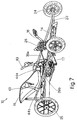
- Figs. 1 and 2 show respective side and plan views of a four-wheel pedal vehicle 10 according to the invention, while the fig. 7 shows a perspective view of the vehicle 10 itself.
- Fig.2 does not show a seat assembly 11 and shows only partly a steering assembly 12.
- the four-wheel pedal vehicle 10 comprises a frame 13 consisting of a central carrying beam 14 embodied with a metallic section or another material and advantageously possessing excellent characteristics of light weight and strength.
- the central beam 14 is pre-arranged for fixture of all the accessories and components required for efficient use of the vehicle 10, such as a support 15 for pedals 16, a change gear assembly 17, a support for a central power distribution assembly 18, a steering pivot 19, etc.
- a structure 20 consisting of metallic sections and having a substantially triangular or trapezoidal shape is associated with the rear of the central beam 14 and bears the seat assembly 11 and a rear brake assembly 21.
- the seat assembly is shaped to provide for the user a seated position characterised by a very low centre of gravity so as to ensure the stability of, and ability to steer, the vehicle in all driving conditions, together with easy mounting thereonto and descent therefrom.
- the position of the change from the seatback portion 11a to the seat portion 11b of the seat assembly 11 is located substantially in the vicinity of the almost horizontal plane joining the front shaft 22 and the rear half-shafts 23.
- the seat assembly 11 is associated with pairs of supporting bars 37 and 38 which enable the seat assembly 11 to be adjusted for height, slope and length.
- the pedals 16 are fitted to a support 15, the position of which along the central beam 14 can be adjusted advantageously according the the user's requirements.
- levers 43 which operate the steering assembly 12 can also be adjusted advantageously as desired by the user.
- the pedals 16 cooperate with a change gear assembly that comprises in this case a first front crown wheel 26 and a plurality of crown wheels 27 located at a substantially intermediate position along the vehicle 10 in cooperation with the central power distribution assembly 18.
- the intermediate crown wheels 27 are secured to the central power distribution assembly 18 and can be actuated individually by hand by the user in a substantially conventional way by means of controls located on the actuation levers 43 but not shown here in detail.
- a dérailleur assembly 28 to displace a chain 29 is included in cooperation with the first front crown wheel 26, while on the outer side of the outermost intermediate crown wheel 27 is located a supporting element 30, which is secured to the central beam 34 and bears the change gear assembly 17.
- This supporting element 30 may also have the task of protecting the intermediate crown wheels 27.
- Motion is transmitted by the specific intermediate crown wheel 27 selected by the user to a pair of first gearwheels 31 solidly fixed to each other through a hub 32 and arranged on opposite sides of the central beam 14.
- These first gearwheels 31 together with the hub 32 form the central power distribution assembly 18 and have the purpose of transmitting the motion from the change gear assembly 17 to a rear differential gear assembly 33.
- the first gearwheels 31 perform a second gearing-up of the motion at a preset ration in relation to their diameter, thus enabling a great number of changes of gear to be obtained with limited stages and with a broad option and range of ratios.
- the thrust equally distributed to the two first gearwheels 31 is eqally divided and transmitted to the rear half-shafts 23 where the vehicle 10 is running straight or where the powered wheels 25 adhere equally to the ground.
- the motive torque is transmitted to the wheel 25 on the inside of the curve or analogously to the wheel 25 adhering more to the ground, owing to the inclusion of the free wheels 36.
- Each rear brake assembly 21 is secured to, and cooperates with, the respective rear wheel-hub 42 assembly, one of which is shown in detail in Fig.4 and supports the end of the respective half-shaft 23 with the relative wheel-hub 40 which secures the respective powered wheel 25.
- the steering assembly 12 comprises actuation levers 43 fixed to frontal levers 39a and 39b, the positioning of which can be adjusted according to the specific ergonomic position required.
- the frontal levers 39a, 39b are secured to the front shaft 22 by pivots 45 and are bent inwards so as not to come into contact with the steering wheels 24 when the vehicle is being steered fully to the right or left.
- Respective guides 44a and 44b slide within the frontal levers 39a, 39b telescopically in the direction 46 and are hinged to the rear upright of the trapezoidal structure 20 of the frame 13; these guides 44a, 44b have the function of guiding and keeping in position the steering assembly 12;
Landscapes
- Engineering & Computer Science (AREA)
- Mechanical Engineering (AREA)
- Chemical & Material Sciences (AREA)
- Combustion & Propulsion (AREA)
- Transportation (AREA)
- Inorganic Insulating Materials (AREA)
- Heat Treatment Of Sheet Steel (AREA)
- Motorcycle And Bicycle Frame (AREA)
- Arrangement And Mounting Of Devices That Control Transmission Of Motive Force (AREA)
- Steering Controls (AREA)
- Diaphragms For Electromechanical Transducers (AREA)
- Mechanical Operated Clutches (AREA)
- Automatic Cycles, And Cycles In General (AREA)
Applications Claiming Priority (2)
| Application Number | Priority Date | Filing Date | Title |
|---|---|---|---|
| IT95UD000188A IT1286181B1 (it) | 1995-09-29 | 1995-09-29 | Veicolo a quattro ruote a pedali |
| ITUD950188 | 1995-09-29 |
Publications (2)
| Publication Number | Publication Date |
|---|---|
| EP0765799A1 true EP0765799A1 (de) | 1997-04-02 |
| EP0765799B1 EP0765799B1 (de) | 1999-12-22 |
Family
ID=11421924
Family Applications (1)
| Application Number | Title | Priority Date | Filing Date |
|---|---|---|---|
| EP96115220A Expired - Lifetime EP0765799B1 (de) | 1995-09-29 | 1996-09-23 | Vier-Räder Tretkurbelfahrzeug |
Country Status (4)
| Country | Link |
|---|---|
| EP (1) | EP0765799B1 (de) |
| AT (1) | ATE187939T1 (de) |
| DE (1) | DE69605744T2 (de) |
| IT (1) | IT1286181B1 (de) |
Cited By (2)
| Publication number | Priority date | Publication date | Assignee | Title |
|---|---|---|---|---|
| WO1999067124A1 (en) * | 1998-06-22 | 1999-12-29 | Giuseppe Bernardini | Human powered vehicle with at least two wheels |
| CN106741416A (zh) * | 2017-01-04 | 2017-05-31 | 刘志国 | 一种具有梯形转向结构的躺车 |
Citations (4)
| Publication number | Priority date | Publication date | Assignee | Title |
|---|---|---|---|---|
| FR665281A (fr) * | 1928-12-06 | 1929-09-17 | Véhicule démontable | |
| WO1984000338A1 (en) * | 1982-07-12 | 1984-02-02 | Colorado Cyclodynamics | Tricycle |
| GB2143185A (en) * | 1983-07-13 | 1985-02-06 | Philip Lewis Cracknell | Road wheel differential for light conveyances |
| DE9204069U1 (de) * | 1992-03-26 | 1992-06-11 | Zato Fahrzeugentwicklungs GmbH, 5485 Sinzig | Vierrädriges, pedalgetriebens Fahrzeug |
-
1995
- 1995-09-29 IT IT95UD000188A patent/IT1286181B1/it active IP Right Grant
-
1996
- 1996-09-23 DE DE69605744T patent/DE69605744T2/de not_active Expired - Fee Related
- 1996-09-23 EP EP96115220A patent/EP0765799B1/de not_active Expired - Lifetime
- 1996-09-23 AT AT96115220T patent/ATE187939T1/de not_active IP Right Cessation
Patent Citations (4)
| Publication number | Priority date | Publication date | Assignee | Title |
|---|---|---|---|---|
| FR665281A (fr) * | 1928-12-06 | 1929-09-17 | Véhicule démontable | |
| WO1984000338A1 (en) * | 1982-07-12 | 1984-02-02 | Colorado Cyclodynamics | Tricycle |
| GB2143185A (en) * | 1983-07-13 | 1985-02-06 | Philip Lewis Cracknell | Road wheel differential for light conveyances |
| DE9204069U1 (de) * | 1992-03-26 | 1992-06-11 | Zato Fahrzeugentwicklungs GmbH, 5485 Sinzig | Vierrädriges, pedalgetriebens Fahrzeug |
Cited By (4)
| Publication number | Priority date | Publication date | Assignee | Title |
|---|---|---|---|---|
| WO1999067124A1 (en) * | 1998-06-22 | 1999-12-29 | Giuseppe Bernardini | Human powered vehicle with at least two wheels |
| US6336646B1 (en) * | 1998-06-22 | 2002-01-08 | Giuseppe Bernardini | Human powered vehicle with at least two wheels |
| CN1093812C (zh) * | 1998-06-22 | 2002-11-06 | 朱塞佩·贝尔纳迪尼 | 至少具有两个轮子的人力车 |
| CN106741416A (zh) * | 2017-01-04 | 2017-05-31 | 刘志国 | 一种具有梯形转向结构的躺车 |
Also Published As
| Publication number | Publication date |
|---|---|
| ITUD950188A1 (it) | 1997-03-29 |
| ATE187939T1 (de) | 2000-01-15 |
| DE69605744D1 (de) | 2000-01-27 |
| EP0765799B1 (de) | 1999-12-22 |
| DE69605744T2 (de) | 2000-08-10 |
| ITUD950188A0 (de) | 1995-09-29 |
| IT1286181B1 (it) | 1998-07-07 |
Similar Documents
| Publication | Publication Date | Title |
|---|---|---|
| US4198072A (en) | Wheeled vehicle | |
| US7213669B2 (en) | Snowmobile rider positioning | |
| US5607171A (en) | Recumbent bicycle | |
| US4456277A (en) | Tricycle | |
| EP1401674B1 (de) | Scooter | |
| US5067738A (en) | Child powered bicycle trailer | |
| US6050584A (en) | Bicycle placing rider in substantially semi-prone riding position | |
| EP0100596B1 (de) | Dreirad | |
| EP0042862A1 (de) | Liegefahrrad | |
| GB2082516A (en) | Vehicle propelled by pedals | |
| WO1994021340A1 (en) | Motor arrangement for roller skater | |
| US5228354A (en) | Multispeed, shaft-driven vehicle drive | |
| US4303256A (en) | Bicycle of the kind having the seat placed low so that the legs of the rider are substantially horizontal | |
| EP0765799B1 (de) | Vier-Räder Tretkurbelfahrzeug | |
| US3885814A (en) | Centrifugal bicycle wheel | |
| US4478305A (en) | Rear suspension for a three wheel vehicle | |
| US5370410A (en) | One-wheeled vehicle | |
| US4059168A (en) | Runner attachment for bicycles with a reaction thrust device | |
| US6012732A (en) | Combination exercise and land travel device | |
| US4792149A (en) | Pedal-powered golf cart | |
| US20160304147A1 (en) | Velocipede | |
| US4126329A (en) | Wheeled vehicle with oar-type propulsion | |
| CA2510361A1 (en) | Bicycle wheel mounting | |
| KR200384084Y1 (ko) | 자전거 | |
| US6505698B1 (en) | End-weighted vehicle |
Legal Events
| Date | Code | Title | Description |
|---|---|---|---|
| PUAI | Public reference made under article 153(3) epc to a published international application that has entered the european phase |
Free format text: ORIGINAL CODE: 0009012 |
|
| AK | Designated contracting states |
Kind code of ref document: A1 Designated state(s): AT BE CH DE ES FR GB IT LI LU MC NL |
|
| AX | Request for extension of the european patent |
Free format text: SI PAYMENT 960923 |
|
| 17P | Request for examination filed |
Effective date: 19970926 |
|
| GRAG | Despatch of communication of intention to grant |
Free format text: ORIGINAL CODE: EPIDOS AGRA |
|
| 17Q | First examination report despatched |
Effective date: 19981112 |
|
| GRAG | Despatch of communication of intention to grant |
Free format text: ORIGINAL CODE: EPIDOS AGRA |
|
| GRAH | Despatch of communication of intention to grant a patent |
Free format text: ORIGINAL CODE: EPIDOS IGRA |
|
| GRAH | Despatch of communication of intention to grant a patent |
Free format text: ORIGINAL CODE: EPIDOS IGRA |
|
| GRAA | (expected) grant |
Free format text: ORIGINAL CODE: 0009210 |
|
| AK | Designated contracting states |
Kind code of ref document: B1 Designated state(s): AT BE CH DE ES FR GB IT LI LU MC NL |
|
| AX | Request for extension of the european patent |
Free format text: SI PAYMENT 19960923 |
|
| PG25 | Lapsed in a contracting state [announced via postgrant information from national office to epo] |
Ref country code: NL Free format text: LAPSE BECAUSE OF FAILURE TO SUBMIT A TRANSLATION OF THE DESCRIPTION OR TO PAY THE FEE WITHIN THE PRESCRIBED TIME-LIMIT Effective date: 19991222 Ref country code: LI Free format text: LAPSE BECAUSE OF FAILURE TO SUBMIT A TRANSLATION OF THE DESCRIPTION OR TO PAY THE FEE WITHIN THE PRESCRIBED TIME-LIMIT Effective date: 19991222 Ref country code: IT Free format text: LAPSE BECAUSE OF FAILURE TO SUBMIT A TRANSLATION OF THE DESCRIPTION OR TO PAY THE FEE WITHIN THE PRE;WARNING: LAPSES OF ITALIAN PATENTS WITH EFFECTIVE DATE BEFORE 2007 MAY HAVE OCCURRED AT ANY TIME BEFORE 2007. THE CORRECT EFFECTIVE DATE MAY BE DIFFERENT FROM THE ONE RECORDED.SCRIBED TIME-LIMIT Effective date: 19991222 Ref country code: FR Free format text: LAPSE BECAUSE OF FAILURE TO SUBMIT A TRANSLATION OF THE DESCRIPTION OR TO PAY THE FEE WITHIN THE PRESCRIBED TIME-LIMIT Effective date: 19991222 Ref country code: ES Free format text: THE PATENT HAS BEEN ANNULLED BY A DECISION OF A NATIONAL AUTHORITY Effective date: 19991222 Ref country code: CH Free format text: LAPSE BECAUSE OF FAILURE TO SUBMIT A TRANSLATION OF THE DESCRIPTION OR TO PAY THE FEE WITHIN THE PRESCRIBED TIME-LIMIT Effective date: 19991222 Ref country code: AT Free format text: LAPSE BECAUSE OF FAILURE TO SUBMIT A TRANSLATION OF THE DESCRIPTION OR TO PAY THE FEE WITHIN THE PRESCRIBED TIME-LIMIT Effective date: 19991222 |
|
| REF | Corresponds to: |
Ref document number: 187939 Country of ref document: AT Date of ref document: 20000115 Kind code of ref document: T |
|
| REG | Reference to a national code |
Ref country code: CH Ref legal event code: EP |
|
| REF | Corresponds to: |
Ref document number: 69605744 Country of ref document: DE Date of ref document: 20000127 |
|
| EN | Fr: translation not filed | ||
| NLV1 | Nl: lapsed or annulled due to failure to fulfill the requirements of art. 29p and 29m of the patents act | ||
| REG | Reference to a national code |
Ref country code: CH Ref legal event code: PL |
|
| PG25 | Lapsed in a contracting state [announced via postgrant information from national office to epo] |
Ref country code: LU Free format text: LAPSE BECAUSE OF NON-PAYMENT OF DUE FEES Effective date: 20000923 Ref country code: GB Free format text: LAPSE BECAUSE OF NON-PAYMENT OF DUE FEES Effective date: 20000923 |
|
| PG25 | Lapsed in a contracting state [announced via postgrant information from national office to epo] |
Ref country code: MC Free format text: THE PATENT HAS BEEN ANNULLED BY A DECISION OF A NATIONAL AUTHORITY Effective date: 20000930 Ref country code: BE Free format text: LAPSE BECAUSE OF NON-PAYMENT OF DUE FEES Effective date: 20000930 |
|
| PLBE | No opposition filed within time limit |
Free format text: ORIGINAL CODE: 0009261 |
|
| STAA | Information on the status of an ep patent application or granted ep patent |
Free format text: STATUS: NO OPPOSITION FILED WITHIN TIME LIMIT |
|
| 26N | No opposition filed | ||
| BERE | Be: lapsed |
Owner name: CENCIGH PAOLO Effective date: 20000930 |
|
| GBPC | Gb: european patent ceased through non-payment of renewal fee |
Effective date: 20000923 |
|
| PG25 | Lapsed in a contracting state [announced via postgrant information from national office to epo] |
Ref country code: DE Free format text: LAPSE BECAUSE OF NON-PAYMENT OF DUE FEES Effective date: 20010601 |