EP0765962B1 - Wartungsgerechte Rauhmaschine mit einer Vorrichtung zum Verhindern von Beschädigungen beim Reissen des Gewebes - Google Patents
Wartungsgerechte Rauhmaschine mit einer Vorrichtung zum Verhindern von Beschädigungen beim Reissen des Gewebes Download PDFInfo
- Publication number
- EP0765962B1 EP0765962B1 EP96830126A EP96830126A EP0765962B1 EP 0765962 B1 EP0765962 B1 EP 0765962B1 EP 96830126 A EP96830126 A EP 96830126A EP 96830126 A EP96830126 A EP 96830126A EP 0765962 B1 EP0765962 B1 EP 0765962B1
- Authority
- EP
- European Patent Office
- Prior art keywords
- raising
- drum
- driven
- raising machine
- cleaning brushes
- Prior art date
- Legal status (The legal status is an assumption and is not a legal conclusion. Google has not performed a legal analysis and makes no representation as to the accuracy of the status listed.)
- Expired - Lifetime
Links
- 239000004744 fabric Substances 0.000 title claims abstract description 17
- 238000012423 maintenance Methods 0.000 title claims abstract description 12
- 238000004140 cleaning Methods 0.000 claims abstract description 31
- 230000002093 peripheral effect Effects 0.000 claims 1
- 230000007717 exclusion Effects 0.000 description 2
- 238000006073 displacement reaction Methods 0.000 description 1
- 230000002452 interceptive effect Effects 0.000 description 1
- 239000000463 material Substances 0.000 description 1
- 238000012986 modification Methods 0.000 description 1
- 230000004048 modification Effects 0.000 description 1
Images


Classifications
-
- D—TEXTILES; PAPER
- D06—TREATMENT OF TEXTILES OR THE LIKE; LAUNDERING; FLEXIBLE MATERIALS NOT OTHERWISE PROVIDED FOR
- D06C—FINISHING, DRESSING, TENTERING OR STRETCHING TEXTILE FABRICS
- D06C11/00—Teasing, napping or otherwise roughening or raising pile of textile fabrics
Definitions
- the present invention relates to an improved maintenance raising machine including a safety device for preventing damages as the fabric being raised is broken.
- raising or teaseling machines As is known, for raising fabrics, are conventionally used specifically designed machines, which are called raising or teaseling machines.
- Prior art raising machines usually comprise a drum, which has a horizontal axis and supports, on the periphery or mantle thereof, a plurality of raising cylinders, constituted by cylinders having the axes thereof parallel to the axis of the drum and coated by card clothings.
- the mentioned raising cylinders are kinematically connected to the drum, so that a rotation of the drum about the axis thereof will also cause the rotation of the raising cylinders about the respective rotary axes.
- This connection is so designed that, alternately, two adjoining raising cylinders are driven in opposite turning directions and the card clothings of two adjoining raising cylinders have the tips of the teeth thereof directed in a mutually opposite direction in order to respectively perform a raising operation and a counter-raising operation on the fabric being raised.
- the fabric being raised, during the advancement movement thereof, is wound nearly on the overall periphery of the drum supporting the raising cylinders, with the exclusion of a bottom region of the drum periphery or mantle, where are arranged one or more cleaning brushes, for cleaning the card clothings of the raising cylinders.
- the cleaning brushes are conventionally driven by opposite rotary movements and are so arranged as to affect one the raising cylinder for performing the raising operation proper, and the other the raising cylinders for performing the counter-raising operation.
- th fabric may contact the cleaning brushes so as to damage the latter, or damage the raising cylinder card clothings, with the requirement of subjecting the assembly to frequent maintenance operations, in order to replace the brushes and, very frequently, also the raising cylinder card clothings.
- EP-A-0 748 407 belongs to the state of the art according to Article 54(3) EPC.
- the aim of the present invention is to solve the above mentioned problem, by providing a raising machine which is very safe against a possible damage of the cleaning brushes and card clothings of the raising cylinders, as a fabric being raised is accidentally broken.
- a main object of the present invention is to provide such a raising machine the maintenance thereof can be performed very easily and quickly.
- Another object of the present invention is to provide such a raising machine which is very safe and reliable in operation.
- Yet another object of the present invention is to provide such a raising machine which can be made starting from easily available materials and elements and which, moreover, has a very reduced cost.
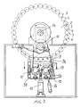
- the raising machine according to the present invention which has been generally indicated by the reference number 1, comprises, in a per se known manner, a rotary drum 2, which is rotatably supported about the rotary axis 2a thereof, horizontally arranged, and which can be rotatively driven about said axis 2a.
- the drum 2 supports, on the periphery or mantle thereof, a plurality of raising cylinders 3 and 4 which are rotatably supported about their respective rotary axes, parallel to the axis 2a of the drum 2.
- the raising cylinders 3 and 4 can be driven by a rotary movement about their respective axes so that, alternately, a raising cylinder 3 is driven in an opposite rotary direction with respect to the rotary direction of the adjoining raising cylinder 4.
- Each raising cylinder 3 or 4 is constituted by a supporting cylinder, which is coated by a card clothing 5.
- the card clothings 5 of the raising cylinders 3 are arranged with the tips of the teeth thereof oriented in a direction, whereas the card clothings of the raising cylinders 4 are arranged with the tips of their teeth facing an opposite direction, so that the raising cylinders 3 are suitable to provide a raising operation on the fabric being raised, whereas the raising cylinder 4 are suitable to provide a counter-raising operation.
- the fabric being raised is caused to be wound on the periphery of the drum 2, so as to contact the raising cylinders 3 and 4, with the exclusion of a bottom portion of the drum 2, therewith are associated in a facing adjoining relationship the cleaning brushes 6 and 7.
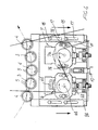
- the cleaning brushes 6 and 7 are rotatably mounted about their respective rotary axes 6a and 7a which are parallel to the axes of the raising cylinders 3 and 4, being supported on a supporting element 8, which, in turn, can be displaced toward the drum 2 or away from said drum 2.
- the supporting element 8 is slidably mounted along vertical guides 9a and 9b in order to be controllably driven along said guides 9a and 9b, manually or, preferably, by means of a pneumatic or hydraulic cylinder 10.
- the cleaning brushes 6 and 7 can be rotatably driven about their respective rotary axes 6a and 7a and in opposite rotary directions, for example by means of a belt drive 11, or a chain drive, and being provided with cleaning portions respectively indicated by the reference numbers 6b and 7b.
- the cleaning portions are suitably offset from one another, so that the cleaning brush 6 will operate exclusively on the raising cylinders 3 providing the raising operation proper, whereas the other cleaning brush 7b will operate exclusively on the raising cylinders 4 providing the counter-raising operation.
- the belt of chain 11 extends along a driving path, by engaging with two pinions or pulleys 12 and 13 rigid with said cleaning brushes 6 and 7 and with a pinion or pulley 14 which can be driven, in a per se known manner, with a rotary motion about the rotary axis thereof, in order to cause the cleaning brushes 6 and 7 to turn.
- a tension pulley or roller 15 which is movable, under the action of a pneumatic or hydraulic cylinder 16, in order to properly tension or stretch the belt or chain 11.
- slots 17 which vertically extend and which restrain, by interfering with bolts 18 affixed to the guides 9a and 9b the displacement stroke of the supporting element 8.
- this maintenance operation can be performed in a very easy manner owing to the fact that the supporting element 8 and cleaning brushes 6 and 7 can be suitably removed from the drum 2.
Landscapes
- Engineering & Computer Science (AREA)
- Textile Engineering (AREA)
- Preliminary Treatment Of Fibers (AREA)
- Treatment Of Fiber Materials (AREA)
- Spinning Or Twisting Of Yarns (AREA)
- General Factory Administration (AREA)
- Beans For Foods Or Fodder (AREA)
- Warping, Beaming, Or Leasing (AREA)
- Investigating Or Analysing Biological Materials (AREA)
- Vehicle Cleaning, Maintenance, Repair, Refitting, And Outriggers (AREA)
- Medicines Containing Antibodies Or Antigens For Use As Internal Diagnostic Agents (AREA)
- Dental Preparations (AREA)
- Harvester Elements (AREA)
Claims (5)
- Eine Rauhmaschine (1) mit verbesserten Wartungseigenschaften, die eine Sicherheitsvorrichtung zur Verhinderung von Schäden einschließt, die beim Zerreißen eines Gewebes auftreten, das aufgerauht wird, wobei diese Rauhmaschine (1) eine Walze (2) mit einer waagrechten Achse (2a) umfaßt, die um diese Achse zur Drehung veranlaßt werden kann und auf einem Bereich ihres Umfanges eine Vielzahl von Rauhzylindern (3, 4) trägt, deren Zylinderachsen parallel zu dieser Achse (2a) dieser Walze (2) verlaufen und die um deren Achsen zur Drehung veranlaßt werden können, wobei ferner eine oder mehrere Reinigungsbürsten (6, 7) bereitgestellt sind und diese Bürsten (6, 7) nahe bei einem Bereich dieses Umfanges dieser Walze (2) liegen und auf diese Rauhzylinder (3, 4) wirken, um diese Rauhzylinder (3, 4) zu reinigen, dadurch gekennzeichnet, daß diese Reinigungsbürsten (6, 7) auf einem steuerbar angetriebenen Tragbauteil (8) angebracht sind, das zu dieser Walze (2) oder von dieser Walze (2) weg bewegt werden kann, wobei sich dieses Tragbauteil (8) nahe eines Bodenbereiches dieser Walze (2) befindet und gleitend auf vertikalen Führungen (9a, 9b) angebracht ist.
- Eine Rauhmaschine nach Anspruch 1, worin dieses Tragbauteil (8) von einem hydraulisch oder pneumatisch betätigten Zylinder auf diesen Führungen (9a, 9b) gleitend zu dieser Walze (2) oder von dieser Walze weg bewegt wird.
- Eine Rauhmaschine nach Anspruch 1, worin diese Reinigungsbürsten (6, 7) eine oder mehrere Reinigungsbürsten (6, 7) umfassen, deren Achsen parallel zur Achse dieser Walze (2) verlaufen und die durch ein Riemen- oder Kettengetriebe (11) um ihre Achsen (6a, 7a) angetrieben werden, wobei ferner eine gesteuerte Spannvorrichtung (15) zum Spannen dieses Riemens bzw. dieser Kette bereitgestellt ist.
- Eine Rauhmaschine nach Anspruch 3, worin diese gesteuerte Spannvorrichtung (15) zumindest eine Spannscheibe bzw. -walze umfaßt, die durch einen hydraulischen oder pneumatischen Zylinder (16) gesteuert betätigt werden kann.
- Eine Rauhmaschine nach Anspruch 1, worin diese Reinigungsbürsten (6, 7) in gegenläufige Drehung versetzt werden und für die abwechselnde Wirkung auf die naheliegenden Rauhzylinder bereitgestellt sind, die um ihre jeweilige Rotationsachsen und mit entgegengesetzten Drehbewegungen angetrieben werden.
Applications Claiming Priority (2)
| Application Number | Priority Date | Filing Date | Title |
|---|---|---|---|
| IT95MI001980A IT1277656B1 (it) | 1995-09-26 | 1995-09-26 | Garzatrice ad elevata semplicita' di manutenzione provvista di un dispositivo di sicurezza contro danneggiamenti in occasione della |
| ITMI951980 | 1995-09-26 |
Publications (2)
| Publication Number | Publication Date |
|---|---|
| EP0765962A1 EP0765962A1 (de) | 1997-04-02 |
| EP0765962B1 true EP0765962B1 (de) | 2000-05-10 |
Family
ID=11372281
Family Applications (1)
| Application Number | Title | Priority Date | Filing Date |
|---|---|---|---|
| EP96830126A Expired - Lifetime EP0765962B1 (de) | 1995-09-26 | 1996-03-20 | Wartungsgerechte Rauhmaschine mit einer Vorrichtung zum Verhindern von Beschädigungen beim Reissen des Gewebes |
Country Status (9)
| Country | Link |
|---|---|
| US (1) | US5644824A (de) |
| EP (1) | EP0765962B1 (de) |
| AT (1) | ATE192792T1 (de) |
| BR (1) | BR9604137A (de) |
| DE (1) | DE69608195T2 (de) |
| ES (1) | ES2147910T3 (de) |
| IT (1) | IT1277656B1 (de) |
| PT (1) | PT765962E (de) |
| TR (1) | TR199600657A2 (de) |
Families Citing this family (2)
| Publication number | Priority date | Publication date | Assignee | Title |
|---|---|---|---|---|
| ITUD20110086A1 (it) * | 2011-06-10 | 2012-12-11 | Lafer Spa | Dispositivo di posizionamento e regolazione automatica, e relativo procedimento, per una o piu' spazzole pulitrici in una macchina finitrice di tessuti e macchina finitrice comprendente tale dispositivo |
| CN111270464B (zh) * | 2020-03-18 | 2022-03-18 | 浙江庄臣新材料有限公司 | 一种可拆换的高色牢度纯棉汗布加工用磨毛机构 |
Family Cites Families (13)
| Publication number | Priority date | Publication date | Assignee | Title |
|---|---|---|---|---|
| US532940A (en) * | 1895-01-22 | bauche | ||
| US577602A (en) * | 1897-02-23 | Nicolas henry grosselin | ||
| US377151A (en) * | 1888-01-31 | grosselin | ||
| US393605A (en) * | 1888-11-27 | bauche | ||
| US485929A (en) * | 1892-11-08 | grosselin | ||
| US511609A (en) * | 1893-12-26 | qessner | ||
| US1154350A (en) * | 1914-01-02 | 1915-09-21 | Davis & Furber | Safety device for time-clearers on nappers. |
| GB195480A (en) * | 1922-01-24 | 1923-04-05 | Thomas Whinray Riley | Improvements in cloth raising machines |
| DE738620C (de) * | 1937-10-27 | 1943-08-25 | Alfred Stein | Trommelrauhmaschine |
| DE1137713B (de) * | 1960-05-14 | 1962-10-11 | Mec Lamperti Off | Rauhmaschine fuer zu einem Ring zusammengenaehte Gewebe, insbesondere fuer die Herstellung von Decken |
| DE4025202C1 (de) * | 1990-08-09 | 1992-01-02 | Gebrueder Sucker + Franz Mueller Gmbh & Co, 4050 Moenchengladbach, De | |
| IT1272535B (it) * | 1993-08-30 | 1997-06-23 | Sperotto Rimar Spa | Macchina garzatrice e/o smerigliatrice per tessuti e maglieria |
| TW313604B (de) * | 1995-01-03 | 1997-08-21 | Comet Spa |
-
1995
- 1995-09-26 IT IT95MI001980A patent/IT1277656B1/it active IP Right Grant
-
1996
- 1996-03-20 ES ES96830126T patent/ES2147910T3/es not_active Expired - Lifetime
- 1996-03-20 DE DE69608195T patent/DE69608195T2/de not_active Expired - Fee Related
- 1996-03-20 EP EP96830126A patent/EP0765962B1/de not_active Expired - Lifetime
- 1996-03-20 AT AT96830126T patent/ATE192792T1/de not_active IP Right Cessation
- 1996-03-20 PT PT96830126T patent/PT765962E/pt unknown
- 1996-04-10 US US08/629,480 patent/US5644824A/en not_active Expired - Fee Related
- 1996-08-09 TR TR96/00657A patent/TR199600657A2/xx unknown
- 1996-08-22 BR BR9604137A patent/BR9604137A/pt active Search and Examination
Also Published As
| Publication number | Publication date |
|---|---|
| BR9604137A (pt) | 1998-05-26 |
| US5644824A (en) | 1997-07-08 |
| TR199600657A2 (tr) | 1997-04-22 |
| DE69608195D1 (de) | 2000-06-15 |
| IT1277656B1 (it) | 1997-11-11 |
| ES2147910T3 (es) | 2000-10-01 |
| ITMI951980A1 (it) | 1997-03-26 |
| EP0765962A1 (de) | 1997-04-02 |
| ITMI951980A0 (de) | 1995-09-26 |
| DE69608195T2 (de) | 2000-11-16 |
| PT765962E (pt) | 2000-08-31 |
| ATE192792T1 (de) | 2000-05-15 |
Similar Documents
| Publication | Publication Date | Title |
|---|---|---|
| RU2187588C2 (ru) | Узел чесания чесальной машины для текстильного волокна, например хлопчатого, химического волокна и тому подобного, с движущимися шляпками, оснащенными гарнитурой | |
| DE69320966T2 (de) | Vorrichtung zum Rauhen von Geweben oder Gestricken mit Ansaugen und Reinigen | |
| US5054166A (en) | Adjustable textile card element and method of use | |
| EP0765962B1 (de) | Wartungsgerechte Rauhmaschine mit einer Vorrichtung zum Verhindern von Beschädigungen beim Reissen des Gewebes | |
| RU2720028C1 (ru) | Устройство для ломки изгибом стеклянных пластин | |
| US7462095B2 (en) | Apparatus at a flat card or roller card for grinding a clothing drawn onto a rotating roller | |
| US5084948A (en) | Textile napping machine | |
| EP1072713B1 (de) | Vorrichtung und Verfahren zum Schmirgeln von Textilmaterial | |
| US5025644A (en) | Sueding means in a textile fabric-producing machine | |
| RU2711095C1 (ru) | Устройство для ломки изгибом стеклянных пластин | |
| US7578729B2 (en) | Apparatus at a flat card or roller card for grinding a clothing drawn onto a rotating roller, having a carrying device | |
| US1913016A (en) | Card cleaning apparatus | |
| JPS5854066B2 (ja) | オリモノキカイヨウイトクリダシソウチ | |
| EP0893527A2 (de) | Vorrichtung zum Abziehen von Strickwaren an Strickmaschinen, insbesondere an Grossrundstrickmaschinen | |
| US2854813A (en) | Spinning machines | |
| CN223645924U (zh) | 一种混纺坯布验卷机 | |
| KR200214407Y1 (ko) | 연약지반 배수장치 | |
| US5117534A (en) | Method for detaching tufts from fiber bales | |
| CN219314152U (zh) | 一种剖幅机调整张紧装置 | |
| CN219709736U (zh) | 一种网布经编机用导纱机构 | |
| JPS61215764A (ja) | 繊維起毛用ワーカ | |
| RU2073727C1 (ru) | Обрабатывающее устройство к машине для механической обработки кож | |
| US2985922A (en) | Separating drums for an automatic feeder for treating-machines of the textile industry | |
| SU666224A1 (ru) | Товароотвод круглов зальной машины | |
| HK40031330A (en) | Surface treatment method for cotton textile yarn |
Legal Events
| Date | Code | Title | Description |
|---|---|---|---|
| PUAI | Public reference made under article 153(3) epc to a published international application that has entered the european phase |
Free format text: ORIGINAL CODE: 0009012 |
|
| AK | Designated contracting states |
Kind code of ref document: A1 Designated state(s): AT CH DE ES FR GB LI PT |
|
| 17P | Request for examination filed |
Effective date: 19970414 |
|
| 17Q | First examination report despatched |
Effective date: 19981201 |
|
| GRAG | Despatch of communication of intention to grant |
Free format text: ORIGINAL CODE: EPIDOS AGRA |
|
| GRAG | Despatch of communication of intention to grant |
Free format text: ORIGINAL CODE: EPIDOS AGRA |
|
| GRAH | Despatch of communication of intention to grant a patent |
Free format text: ORIGINAL CODE: EPIDOS IGRA |
|
| GRAH | Despatch of communication of intention to grant a patent |
Free format text: ORIGINAL CODE: EPIDOS IGRA |
|
| GRAA | (expected) grant |
Free format text: ORIGINAL CODE: 0009210 |
|
| AK | Designated contracting states |
Kind code of ref document: B1 Designated state(s): AT CH DE ES FR GB LI PT |
|
| REF | Corresponds to: |
Ref document number: 192792 Country of ref document: AT Date of ref document: 20000515 Kind code of ref document: T |
|
| REG | Reference to a national code |
Ref country code: CH Ref legal event code: EP |
|
| REF | Corresponds to: |
Ref document number: 69608195 Country of ref document: DE Date of ref document: 20000615 |
|
| REG | Reference to a national code |
Ref country code: CH Ref legal event code: NV Representative=s name: CABINET ROLAND NITHARDT CONSEILS EN PROPRIETE INDU |
|
| ET | Fr: translation filed | ||
| REG | Reference to a national code |
Ref country code: PT Ref legal event code: SC4A Free format text: AVAILABILITY OF NATIONAL TRANSLATION Effective date: 20000529 |
|
| REG | Reference to a national code |
Ref country code: ES Ref legal event code: FG2A Ref document number: 2147910 Country of ref document: ES Kind code of ref document: T3 |
|
| PLBE | No opposition filed within time limit |
Free format text: ORIGINAL CODE: 0009261 |
|
| STAA | Information on the status of an ep patent application or granted ep patent |
Free format text: STATUS: NO OPPOSITION FILED WITHIN TIME LIMIT |
|
| 26N | No opposition filed | ||
| REG | Reference to a national code |
Ref country code: GB Ref legal event code: IF02 |
|
| PGFP | Annual fee paid to national office [announced via postgrant information from national office to epo] |
Ref country code: FR Payment date: 20020306 Year of fee payment: 7 Ref country code: ES Payment date: 20020306 Year of fee payment: 7 |
|
| PGFP | Annual fee paid to national office [announced via postgrant information from national office to epo] |
Ref country code: PT Payment date: 20020308 Year of fee payment: 7 |
|
| PGFP | Annual fee paid to national office [announced via postgrant information from national office to epo] |
Ref country code: CH Payment date: 20020312 Year of fee payment: 7 |
|
| PGFP | Annual fee paid to national office [announced via postgrant information from national office to epo] |
Ref country code: AT Payment date: 20020314 Year of fee payment: 7 |
|
| PGFP | Annual fee paid to national office [announced via postgrant information from national office to epo] |
Ref country code: GB Payment date: 20020320 Year of fee payment: 7 |
|
| PGFP | Annual fee paid to national office [announced via postgrant information from national office to epo] |
Ref country code: DE Payment date: 20020323 Year of fee payment: 7 |
|
| PG25 | Lapsed in a contracting state [announced via postgrant information from national office to epo] |
Ref country code: GB Free format text: LAPSE BECAUSE OF NON-PAYMENT OF DUE FEES Effective date: 20030320 Ref country code: AT Free format text: LAPSE BECAUSE OF NON-PAYMENT OF DUE FEES Effective date: 20030320 |
|
| PG25 | Lapsed in a contracting state [announced via postgrant information from national office to epo] |
Ref country code: ES Free format text: LAPSE BECAUSE OF NON-PAYMENT OF DUE FEES Effective date: 20030321 |
|
| PG25 | Lapsed in a contracting state [announced via postgrant information from national office to epo] |
Ref country code: LI Free format text: LAPSE BECAUSE OF NON-PAYMENT OF DUE FEES Effective date: 20030331 Ref country code: CH Free format text: LAPSE BECAUSE OF NON-PAYMENT OF DUE FEES Effective date: 20030331 |
|
| PG25 | Lapsed in a contracting state [announced via postgrant information from national office to epo] |
Ref country code: PT Free format text: LAPSE BECAUSE OF NON-PAYMENT OF DUE FEES Effective date: 20030930 |
|
| PG25 | Lapsed in a contracting state [announced via postgrant information from national office to epo] |
Ref country code: DE Free format text: LAPSE BECAUSE OF NON-PAYMENT OF DUE FEES Effective date: 20031001 |
|
| GBPC | Gb: european patent ceased through non-payment of renewal fee |
Effective date: 20030320 |
|
| REG | Reference to a national code |
Ref country code: CH Ref legal event code: PL |
|
| PG25 | Lapsed in a contracting state [announced via postgrant information from national office to epo] |
Ref country code: FR Free format text: LAPSE BECAUSE OF NON-PAYMENT OF DUE FEES Effective date: 20031127 |
|
| REG | Reference to a national code |
Ref country code: PT Ref legal event code: MM4A Free format text: LAPSE DUE TO NON-PAYMENT OF FEES Effective date: 20030930 |
|
| REG | Reference to a national code |
Ref country code: FR Ref legal event code: ST |
|
| REG | Reference to a national code |
Ref country code: ES Ref legal event code: FD2A Effective date: 20030321 |