EP0765992A1 - Dispositif de commande d'un etage d'aubes à calage variable - Google Patents
Dispositif de commande d'un etage d'aubes à calage variable Download PDFInfo
- Publication number
- EP0765992A1 EP0765992A1 EP96402040A EP96402040A EP0765992A1 EP 0765992 A1 EP0765992 A1 EP 0765992A1 EP 96402040 A EP96402040 A EP 96402040A EP 96402040 A EP96402040 A EP 96402040A EP 0765992 A1 EP0765992 A1 EP 0765992A1
- Authority
- EP
- European Patent Office
- Prior art keywords
- cams
- control
- articulated
- fixed
- cam
- Prior art date
- Legal status (The legal status is an assumption and is not a legal conclusion. Google has not performed a legal analysis and makes no representation as to the accuracy of the status listed.)
- Granted
Links
Images



Classifications
-
- F—MECHANICAL ENGINEERING; LIGHTING; HEATING; WEAPONS; BLASTING
- F01—MACHINES OR ENGINES IN GENERAL; ENGINE PLANTS IN GENERAL; STEAM ENGINES
- F01D—NON-POSITIVE DISPLACEMENT MACHINES OR ENGINES, e.g. STEAM TURBINES
- F01D17/00—Regulating or controlling by varying flow
- F01D17/10—Final actuators
- F01D17/12—Final actuators arranged in stator parts
- F01D17/14—Final actuators arranged in stator parts varying effective cross-sectional area of nozzles or guide conduits
- F01D17/16—Final actuators arranged in stator parts varying effective cross-sectional area of nozzles or guide conduits by means of nozzle vanes
- F01D17/162—Final actuators arranged in stator parts varying effective cross-sectional area of nozzles or guide conduits by means of nozzle vanes for axial flow, i.e. the vanes turning around axes which are essentially perpendicular to the rotor centre line
-
- F—MECHANICAL ENGINEERING; LIGHTING; HEATING; WEAPONS; BLASTING
- F04—POSITIVE - DISPLACEMENT MACHINES FOR LIQUIDS; PUMPS FOR LIQUIDS OR ELASTIC FLUIDS
- F04D—NON-POSITIVE-DISPLACEMENT PUMPS
- F04D29/00—Details, component parts, or accessories
- F04D29/40—Casings; Connections of working fluid
- F04D29/52—Casings; Connections of working fluid for axial pumps
- F04D29/54—Fluid-guiding means, e.g. diffusers
- F04D29/56—Fluid-guiding means, e.g. diffusers adjustable
- F04D29/563—Fluid-guiding means, e.g. diffusers adjustable specially adapted for elastic fluid pumps
Definitions
- the invention relates to a device for controlling a stage of pivoting or variable-pitch blades.
- the pivots of the blades, which pass through the stator, are joined to control levers all connected to a control ring which surrounds the stator and which a control mechanism rotates.
- control mechanisms which involve the use of an actuating member such as a jack and a transmission mechanism composed of levers, connecting rods, etc.
- the characteristics of these transmissions are quite varied and some allow non-linear control of the blades, that is to say that the rotation of the latter is not proportional to the movement of the actuator.
- the invention belongs to this kind of control devices and its essential advantage is that the transmission is particularly simple.
- the invention relates to a device for controlling a stage of variable-pitch vanes provided with levers joined to a control ring, the control ring being articulated to a cam pivoting around a first fixed axis, characterized in that the cam is joined to a control crank rotating around a second fixed axis parallel to the first axis by a link articulated to the cam and to the rotating crank at points distinct from the fixed axes.
- the control device can moreover relate to several stages of blades and several control rings at the same time.
- there are other cams articulated by pivoting around other first axes fixed to other control rings of other stages of blades with variable setting the other cams being interconnected and to the rotating crank by a synchronization bar articulated to the other cams and to the crank in identical positions with respect to the other first fixed axes and to the second fixed axis.
- FIG. 1 represents the inlet of a turbomachine with in particular a low pressure compressor section 1 and a high pressure compressor section 2. It is on this that the invention is established.
- Each of the compressors is above all composed of stages of fixed vanes 3 and movable vanes 4 which alternate, some attached to a stator 5 which surrounds the annular vein 6 of gas circulation and the others fixed to a rotor 7 delimiting vein 6, and turning with it.
- the fixed blades 3 can actually pivot around a pivot 8 passing through the stator 5.
- the pivot 8 of each of the blades 3 is terminated by a lever 9.
- the levers 9 of each of the blade stages are united to a ring of command 10 common.
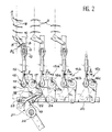
- a pin 17 fixed on the stator is established at the elbow of the cam 15 to allow it to rotate, and its other arm 18 extends opposite the transmission rod 12 and carries at its end another articulation 19 intended to support a synchronization bar 20 perpendicular to the control ring 10, that is to say arranged in the axial direction of the machine.
- the synchronization bar 20 is similarly articulated to other cams 15 assigned to the control of other stages of fixed blades 3 by transmissions similar to that just described and which notably include a control ring 10 for each of the floors.
- the only difference is that the other cams, noted 15a, 15b, 15c, etc., have arms 16a, 16b or 16c, etc.
- the control mechanism unlike a solution previously adopted by the applicant, does not consist of a lever fixed to the fixed axis 17 of the cam 15 considered first, and the purpose of which is to rotate the latter to pull or push on the control rods 12 via all the cams 15 and the synchronization bar 20. Instead, there is a crank 21 rotating around a second fixed axis 26 parallel to the first fixed axes 17, 17a, 17b, 17c, etc., and a connecting rod 22 whose ends are articulated, for the first 23 at the end of the crank 21, and for the second 24 to a part of the second arm 18 distant from the fixed axis 17.
- the angle ⁇ is therefore a sinusoidal function of the angle ⁇ .
- the crank 21 can be turned by the rod 27 of a jack 28 articulated at a fixed point 29, according to a usual design.
- angles ⁇ of rotation imposed on the levers 9 and on the blades 3 are different for the various stages, and more precisely, they are proportional to the lengths l, la, lb, lc, etc., of the arms 16 between the fixed axis 17 and the articulation 14 of the transmission rod 12, that is to say that the laws of rotation are all sinusoidal.
- the cam 15, now denoted 115 is not connected to the synchronization bar 20 and its second arm 18 is replaced by an arm 118 of another shape intended to receive a joint 123 uniting it at one end of a connecting rod 122 similar or similar to the connecting rod 22 and the other end of which is joined by a joint 124 to a protrusion 125 formed on a cam 115a moreover similar to the cam 15a and situated in the same place.
- Another difference consists in that the fixed axis 117a of articulation of the cam 115a is not an inert axis but a control axis dependent on the actuator member.
- the crank 21 of the previous embodiment is eliminated and the cam 115a is a motor lever.
Landscapes
- Engineering & Computer Science (AREA)
- Mechanical Engineering (AREA)
- General Engineering & Computer Science (AREA)
- Control Of Turbines (AREA)
- Transmission Devices (AREA)
Abstract
Description
- L'invention se rapporte à un dispositif de commande d'un étage d'aubes pivotantes ou à calage variable.
- On rencontre de telles aubes sur les stators de certains moteurs d'avions : selon les régimes de la machine, on éprouve le besoin de redresser plus ou moins le flux du gaz qui passe par ces étages d'aubes, qu'on fait donc pivoter autour de leur axe sous l'action d'un mécanisme de commande situé de l'autre côté du stator.
- Les pivots des aubes, qui traversent le stator, sont unis à des leviers de commande tous reliés à un anneau de commande qui entoure le stator et qu'un mécanisme de commande fait tourner.
- Il existe de nombreux genres de mécanismes de commande, qui impliquent l'emploi d'un organe actionneur tel qu'un vérin et d'un mécanisme de transmission composé de leviers, de bielles, etc. Les caractéristiques de ces transmissions sont assez variées et certaines permettent des commandes non linéaires des aubes, c'est-à-dire que la rotation du celles-ci n'est pas proportionnelle au déplacement de l'actionneur. L'invention appartient à ce genre de dispositifs de commande et son avantage essentiel est que la transmission est particulièrement simple.
- Sous la forme la plus générale, l'invention concerne un dispositif de commande d'un étage d'aubes à calage variable munies de leviers réunis à un anneau de commande, l'anneau de commande étant articulé à une came pivotant autour d'un premier axe fixe, caractérisé en ce que la came est unie à une manivelle de commande tournant autour d'un second axe fixe parallèle au premier axe par une biellette articulée à la came et à la manivelle tournante en des points distincts des axes fixes.
- Le dispositif de commande peut d'ailleurs concerner plusieurs étages d'aubes et plusieurs anneaux de commande à la fois. Pour appliquer l'invention, il est alors possible de disposer d'autres cames articulées en pivotant autour d'autres premiers axes fixes à d'autres anneaux de commande d'autres étages d'aubes à calage variable, les cames étant reliées entre elles par une barre de synchronisation articulée aux cames à des positions identiques par rapport aux premiers axes fixes. Ou encore, dans une conception différente, on dispose d'autres cames articulées en pivotant autour d'autres premiers axes fixes à d'autres anneaux de commande d'autres étages d'aubes à calage variable, les autres cames étant reliées entre elles et à la manivelle tournante par une barre de synchronisation articulée aux autres cames et à la manivelle à des positions identiques par rapport aux autres premiers axes fixes et au second axe fixe.
- L'invention va maintenant être décrite plus en détail à l'aide des figures suivantes, qui sont annexées à titre illustratif et non limitatif :
- la figure 1 représente une vue générale d'implantation de l'invention,
- les figures 2 et 3 représentent une première réalisation de l'invention, et
- la figure 4 représente une autre réalisation de l'invention.
- La figure 1 représente l'entrée d'une turbomachine avec notamment une section de compresseur à basse pression 1 et une section de compresseur à haute pression 2. C'est sur celle-ci que l'invention est établie. Chacun des compresseurs est avant tout composé d'étages d'aubes fixes 3 et d'aubes mobiles 4 qui alternent, les unes attachées à un stator 5 qui entoure la veine 6 annulaire de circulation des gaz et les autres fixées à un rotor 7 délimitant la veine 6, et tournant avec lui.
- Les aubes fixes 3 peuvent en réalité pivoter autour d'un pivot 8 traversant le stator 5. Le pivot 8 de chacune des aubes 3 est terminé par un levier 9. Les leviers 9 de chacun des étages d'aubes sont unis à un anneau de commande 10 commun.
- On voit aux figure 2 et 3 que la réunion des leviers 9 d'un étage à l'anneau de commande 10 associé est faite par des articulations 11 qui maintiennent l'anneau de commande 10 tout en lui permettant cependant de tourner sur lui-même. Cela peut être accompli en munissant l'anneau de commande d'une tige de transmission 12 dont une extrémité 13 est articulée à lui, de façon à permettre des déplacements angulaires de la tige de transmission 12, et dont l'autre extrémité 14 est articulée à une came 15 en forme de levier coudé et plus précisément au bout d'un des bras 16 de ce levier coudé.
- Un axe 17 fixe sur le stator est établi au coude de la came 15 pour lui permettre de tourner, et son autre bras 18 s'étend à l'opposé de la tige de transmission 12 et porte à son extrémité une autre articulation 19 destinée à soutenir une barre de synchronisation 20 perpendiculaire à l'anneau de commande 10, c'est-à-dire disposée dans le sens axial de la machine. La barre de synchronisation 20 est pareillement articulée à d'autres cames 15 affectées à la commande d'autres étages d'aubes fixes 3 par des transmissions semblables à celle qu'on vient de décrire et qui comprennent notamment un anneau de commande 10 pour chacun des étages. La seule différence consiste en ce que les autres cames, notées 15a, 15b, 15c, etc., ont des bras 16a, 16b ou 16c, etc. articulés aux tiges de transmission 12 de longueurs différentes ℓ, ℓa, ℓb, ℓc, etc. Cela permettra, comme on le verra clairement d'ici peu, de commander différemment les étages d'aubes fixes 3, c'est-à-dire de leur imposer des rotations différentes. Mais les seconds bras 18 ont tous la même longueur et sont parallèles, si bien que la barre de synchronisation 20 est articulée aux cames 15, 15a, 15b, 15c, etc., à une position identique des axes fixes 17, 17a, 17b, 17c, etc.
- Le mécanisme de commande, contrairement à une solution précédemment adoptée par la demanderesse, ne consiste pas en un levier fixé à l'axe fixe 17 de la came 15 considérée en premier, et dont le but est de faire tourner celui-ci pour tirer ou pousser sur les tiges de commande 12 par l'intermédiaire de toutes les cames 15 et de la barre de synchronisation 20. Au lieu de cela, on dispose une manivelle 21 tournante autour d'un second axe fixe 26 parallèle aux premiers axes fixes 17, 17a, 17b, 17c, etc., et une bielle 22 dont les extrémités sont articulées, pour la première 23 à l'extrémité de la manivelle 21, et pour la seconde 24 à une partie du second bras 18 éloignée de l'axe fixe 17.
- Les lois de commande de l'angle β de rotation des aubes 3 en fonction de l'angle α de rotation de la manivelle 21 dépendent essentiellement de la longueur L de la bielle 22 entre les articulations 23 et 24 et de rayons R1 et R2 mesurés sur les cames 15 entre l'axe fixe 17 et les articulations 14 et 24. On obtient finalement, avec ce mécanisme où la manivelle 21, la bielle 22, les cames 15, 15a, 15b, 15c, etc., la barre de synchronisation 20 et les tiges de commande 12 s'étendent sensiblement dans un plan perpendiculaire aux axes fixes 17, 17a, 17b, 17c, etc. et 26, la formule suivante à partir de positions angulaires d'origine α0 et β0 :


- L'angle β est donc une fonction sinusoïdale de l'angle α.
- La manivelle 21 peut être tournée par la tige 27 d'un vérin 28 articulé à un point fixe 29, selon une conception usuelle.
- Les angles β de rotation infligés aux leviers 9 et aux aubes 3 sont différents pour les divers étages, et plus précisément, ils sont proportionnels aux longueurs ℓ, ℓa, ℓb, ℓc, etc., des bras 16 entre l'axe fixe 17 et l'articulation 14 de la tige de transmission 12, c'est-à-dire que les lois de rotation sont toutes sinusoïdales.
- Dans la conception de la figure 4, un des étages d'aubes fixes 3, celui de gauche sur la figure, est de même déplacé selon suivant une loi non linéaire, mais les autres obéissent à une loi proportionnelle avec les déplacements de l'actionneur. Avec les notations des figures 2 et 3, on retrouve la barre de synchronisation 20 à laquelle sont articulés les cames 15b, 15c, etc. Les modifications concernent les cames 15 et 15a : la came 15, notée désormais 115, n'est pas reliée à la barre de synchronisation 20 et son second bras 18 est remplacé par un bras 118 d'une autre forme destiné à recevoir une articulation 123 l'unissant à une extrémité d'une bielle 122 analogue ou semblable à la bielle 22 et dont l'autre extrémité est réunie par une articulation 124 à une excroissance 125 ménagée sur une came 115a par ailleurs semblable à la came 15a et située au même endroit. Une autre différence consiste en ce que l'axe 117a fixe d'articulation de la came 115a n'est pas un axe inerte mais un axe de commande dépendant de l'organe actionneur. En un mot, la manivelle 21 de la réalisation précédente est supprimée et la came 115a est un levier moteur.
Claims (3)
- Dispositif de commande d'un étage d'aubes (3) à calage variable munies de leviers (9) réunis à un anneau de commande (10), l'anneau de commande (10) étant articulé à une came (15, 115) pivotant autour d'un premier axe fixe (17), caractérisé en ce que la came (15, 115) est unie à une manivelle de commande (21, 115a) tournant autour d'un second axe fixe (26, 117a) parallèle au premier axe fixe (17) par une biellette (22, 122) articulée à la came et à la manivelle tournante en des points distincts des axes fixes.
- Dispositif de commande suivant la revendication 1, caractérisé en ce qu'il comprend d'autres cames (15a, 15b, 15c, ...) articulées en pivotant autour d'autres premiers axes fixes (17a, 17b, 17c,...) à d'autres anneaux de commande (10) d'autres étages d'aubes (3) à calage variable, les cames étant reliées entre elles par une barre de synchronisation (20) articulée aux cames à des positions identiques par rapport aux premiers axes fixes.
- Dispositif de commande suivant la revendication 1, caractérisé en ce qu'il comprend d'autres cames (15b, 15c, ...) articulées en pivotant autour d'autres premiers axes fixes (17b, 17c, ...) à d'autres anneaux de commande d'autres étages d'aubes à calage variable, les autres cames étant reliées entre elles et à la manivelle tournante (115a) par une barre de synchronisation (20) articulée aux autres cames et à la manivelle tournante à des positions identiques par rapport aux autres premiers axes fixes et au second axe fixe (117a).
Applications Claiming Priority (2)
| Application Number | Priority Date | Filing Date | Title |
|---|---|---|---|
| FR9511301 | 1995-09-27 | ||
| FR9511301A FR2739137B1 (fr) | 1995-09-27 | 1995-09-27 | Dispositif de commande d'un etage d'aubes a calage variable |
Publications (2)
| Publication Number | Publication Date |
|---|---|
| EP0765992A1 true EP0765992A1 (fr) | 1997-04-02 |
| EP0765992B1 EP0765992B1 (fr) | 2001-08-29 |
Family
ID=9482943
Family Applications (1)
| Application Number | Title | Priority Date | Filing Date |
|---|---|---|---|
| EP96402040A Expired - Lifetime EP0765992B1 (fr) | 1995-09-27 | 1996-09-26 | Dispositif de commande d'un etage d'aubes à calage variable |
Country Status (4)
| Country | Link |
|---|---|
| US (1) | US5692879A (fr) |
| EP (1) | EP0765992B1 (fr) |
| DE (1) | DE69614794T2 (fr) |
| FR (1) | FR2739137B1 (fr) |
Cited By (3)
| Publication number | Priority date | Publication date | Assignee | Title |
|---|---|---|---|---|
| EP1724472A3 (fr) * | 2005-05-17 | 2009-01-21 | Snecma | Système de commande d'étages d'aubes de stator à angle de calage variable de turbomachine |
| US8915703B2 (en) | 2011-07-28 | 2014-12-23 | United Technologies Corporation | Internally actuated inlet guide vane for fan section |
| WO2021038161A1 (fr) * | 2019-08-27 | 2021-03-04 | Safran Aircraft Engines | Guignol pour un dispositif de calage variable d'une turbomachine |
Families Citing this family (28)
| Publication number | Priority date | Publication date | Assignee | Title |
|---|---|---|---|---|
| FR2856424B1 (fr) * | 2003-06-20 | 2005-09-23 | Snecma Moteurs | Dispositif de calage variable de deux etages d'aubes fixes sur un turboreacteur |
| RU2287064C2 (ru) * | 2004-12-07 | 2006-11-10 | Федеральное государственное унитарное предприятие "Московское машиностроительное производственное предприятие "САЛЮТ" (ФГУП "ММПП "САЛЮТ") | Статор компрессора газотурбинного двигателя |
| FR2887939B1 (fr) * | 2005-06-29 | 2016-09-30 | Soc Nat D'etude Et De Construction De Moteurs D'aviation Snecma | Compresseur multi-etages de turbomachine |
| DE102007012119A1 (de) * | 2007-03-13 | 2008-09-18 | Rolls-Royce Deutschland Ltd & Co Kg | Drosselgradabhängige Schaufelverstellung bei Strömungsarbeitsmaschinen |
| GB0907461D0 (en) * | 2009-05-01 | 2009-06-10 | Rolls Royce Plc | Control mechanism |
| RU2474698C1 (ru) * | 2011-10-28 | 2013-02-10 | Российская Федерация, от имени которой выступает Министерство промышленности и торговли Российской Федерации (Минпромторг России) | Система управления ступенями поворотных лопаток статора компрессора высокого давления |
| US20140010637A1 (en) * | 2012-07-05 | 2014-01-09 | United Technologies Corporation | Torque box and linkage design |
| US9885291B2 (en) * | 2012-08-09 | 2018-02-06 | Snecma | Turbomachine comprising a plurality of fixed radial blades mounted upstream of the fan |
| US9879561B2 (en) * | 2012-08-09 | 2018-01-30 | Snecma | Turbomachine comprising a plurality of fixed radial blades mounted upstream of the fan |
| DE102012021876A1 (de) | 2012-11-07 | 2014-05-22 | Rolls-Royce Deutschland Ltd & Co Kg | Leitschaufelverstellvorrichtung einer Gasturbine |
| FR3033007B1 (fr) * | 2015-02-19 | 2018-07-13 | Safran Aircraft Engines | Dispositif pour le reglage individuel d'une pluralite d'aubes radiales fixes a calage variable dans une turbomachine |
| US10519797B2 (en) | 2016-06-27 | 2019-12-31 | General Electric Company | Turbine engine and stator vane pitch adjustment system therefor |
| US10704412B2 (en) * | 2018-10-05 | 2020-07-07 | Raytheon Technologies Corporation | Bell crank and bar assembly |
| FR3107319B1 (fr) * | 2020-02-19 | 2022-08-12 | Safran Aircraft Engines | Module de turbomachine equipe de systeme de changement de pas des pales d’aubes de stator |
| PL437817A1 (pl) * | 2021-05-07 | 2022-11-14 | General Electric Company | Układ o zmiennej geometrii i działaniu rozdzielonym do sprężarki silnika turbinowego |
| US11560810B1 (en) | 2021-07-20 | 2023-01-24 | Rolls-Royce North American Technologies Inc. | Variable vane actuation system and method for gas turbine engine performance management |
| US11788429B2 (en) * | 2021-08-25 | 2023-10-17 | Rolls-Royce Corporation | Variable tandem fan outlet guide vanes |
| US11802490B2 (en) * | 2021-08-25 | 2023-10-31 | Rolls-Royce Corporation | Controllable variable fan outlet guide vanes |
| DE102021123772A1 (de) | 2021-09-14 | 2023-03-16 | MTU Aero Engines AG | Verstellanordnung für verstellschaufeln einer strömungsmaschine |
| DE102022103922A1 (de) | 2022-02-18 | 2023-08-24 | MTU Aero Engines AG | Hebel zum verstellen einer verstellschaufel |
| FR3133367B1 (fr) * | 2022-03-11 | 2024-08-23 | Safran Aircraft Engines | Propulseur aeronautique |
| BE1030421B1 (fr) * | 2022-04-05 | 2023-10-30 | Safran Aero Boosters | Stator tandem |
| CN115013491A (zh) * | 2022-06-30 | 2022-09-06 | 中国航发贵阳发动机设计研究所 | 一种压气机静子叶片调节机构传动系统 |
| US11834966B1 (en) | 2022-12-30 | 2023-12-05 | Rolls-Royce North American Technologies Inc. | Systems and methods for multi-dimensional variable vane stage rigging utilizing adjustable alignment mechanisms |
| US12146415B2 (en) | 2022-12-30 | 2024-11-19 | Rolls-Royce North American Technologies Inc. | Systems and methods for multi-dimensional variable vane stage rigging utilizing adjustable bracket plates |
| US12000292B1 (en) | 2022-12-30 | 2024-06-04 | Rolls-Royce North American Technologies Inc. | Systems and methods for multi-dimensional variable vane stage rigging |
| US11982193B1 (en) | 2022-12-30 | 2024-05-14 | Rolls-Royce North American Technologies Inc. | Systems and methods for multi-dimensional variable vane stage rigging utilizing adjustable inclined mechanisms |
| US12000293B1 (en) | 2022-12-30 | 2024-06-04 | Rolls-Royce North American Technologies Inc. | Systems and methods for multi-dimensional variable vane stage rigging utilizing coupling mechanisms |
Citations (6)
| Publication number | Priority date | Publication date | Assignee | Title |
|---|---|---|---|---|
| US2999630A (en) * | 1957-08-08 | 1961-09-12 | Gen Electric | Compressor |
| DE1601625A1 (de) * | 1966-01-10 | 1970-08-06 | Rolls Royce | Schaufelbetaetigungsmechanismus,insbesondere fuer Leitradschaufeln in Gasturbinenstrahltriebwerken |
| US4295784A (en) * | 1979-09-26 | 1981-10-20 | United Technologies Corporation | Variable stator |
| US4400135A (en) * | 1981-04-06 | 1983-08-23 | General Motors Corporation | Vane actuation system |
| EP0094296A1 (fr) * | 1982-05-04 | 1983-11-16 | Societe Nationale D'etude Et De Construction De Moteurs D'aviation, "S.N.E.C.M.A." | Dispositif de réglage de la perte de charge d'au moins un des flux dans un turboréacteur multiflux |
| GB2187237A (en) * | 1986-02-28 | 1987-09-03 | Mtu Muenchen Gmbh | Independently adjustable vanes of a tandem guide vane array in a turbocompressor |
Family Cites Families (4)
| Publication number | Priority date | Publication date | Assignee | Title |
|---|---|---|---|---|
| GB2227527B (en) * | 1989-01-25 | 1993-06-09 | Rolls Royce Plc | A variable stator vane arrangement for an axial flow compressor |
| DE3913102C1 (fr) * | 1989-04-21 | 1990-05-31 | Mtu Muenchen Gmbh | |
| FR2681640B1 (fr) * | 1991-09-25 | 1993-11-19 | Snecma | Turbomachine a aubes de stator a calage variable. |
| FR2708311B1 (fr) * | 1993-07-28 | 1995-09-01 | Snecma | Stator de turbomachine à aubes pivotantes et anneau de commande. |
-
1995
- 1995-09-27 FR FR9511301A patent/FR2739137B1/fr not_active Expired - Fee Related
-
1996
- 1996-09-20 US US08/717,193 patent/US5692879A/en not_active Expired - Lifetime
- 1996-09-26 EP EP96402040A patent/EP0765992B1/fr not_active Expired - Lifetime
- 1996-09-26 DE DE69614794T patent/DE69614794T2/de not_active Expired - Lifetime
Patent Citations (6)
| Publication number | Priority date | Publication date | Assignee | Title |
|---|---|---|---|---|
| US2999630A (en) * | 1957-08-08 | 1961-09-12 | Gen Electric | Compressor |
| DE1601625A1 (de) * | 1966-01-10 | 1970-08-06 | Rolls Royce | Schaufelbetaetigungsmechanismus,insbesondere fuer Leitradschaufeln in Gasturbinenstrahltriebwerken |
| US4295784A (en) * | 1979-09-26 | 1981-10-20 | United Technologies Corporation | Variable stator |
| US4400135A (en) * | 1981-04-06 | 1983-08-23 | General Motors Corporation | Vane actuation system |
| EP0094296A1 (fr) * | 1982-05-04 | 1983-11-16 | Societe Nationale D'etude Et De Construction De Moteurs D'aviation, "S.N.E.C.M.A." | Dispositif de réglage de la perte de charge d'au moins un des flux dans un turboréacteur multiflux |
| GB2187237A (en) * | 1986-02-28 | 1987-09-03 | Mtu Muenchen Gmbh | Independently adjustable vanes of a tandem guide vane array in a turbocompressor |
Cited By (5)
| Publication number | Priority date | Publication date | Assignee | Title |
|---|---|---|---|---|
| EP1724472A3 (fr) * | 2005-05-17 | 2009-01-21 | Snecma | Système de commande d'étages d'aubes de stator à angle de calage variable de turbomachine |
| US8915703B2 (en) | 2011-07-28 | 2014-12-23 | United Technologies Corporation | Internally actuated inlet guide vane for fan section |
| WO2021038161A1 (fr) * | 2019-08-27 | 2021-03-04 | Safran Aircraft Engines | Guignol pour un dispositif de calage variable d'une turbomachine |
| FR3100272A1 (fr) * | 2019-08-27 | 2021-03-05 | Safran Aircraft Engines | Guignol pour un dispositif de calage variable d’une turbomachine |
| US12055051B2 (en) | 2019-08-27 | 2024-08-06 | Safran Aircraft Engines | Bellcrank for a variable adjustment device for a turbomachine |
Also Published As
| Publication number | Publication date |
|---|---|
| DE69614794D1 (de) | 2001-10-04 |
| FR2739137B1 (fr) | 1997-10-31 |
| DE69614794T2 (de) | 2002-05-23 |
| EP0765992B1 (fr) | 2001-08-29 |
| FR2739137A1 (fr) | 1997-03-28 |
| US5692879A (en) | 1997-12-02 |
Similar Documents
| Publication | Publication Date | Title |
|---|---|---|
| EP0765992B1 (fr) | Dispositif de commande d'un etage d'aubes à calage variable | |
| EP1489267B1 (fr) | Dispositif de calage variable de deux étages d'aubes fixé sur un turboréacteur | |
| FR2582729A1 (fr) | Levier de manoeuvre pour aubes de stators variables | |
| EP1724472B1 (fr) | Système de commande d'étages d'aubes de stator à angle de calage variable de turbomachine | |
| EP0009447B1 (fr) | Articulation pour bras de manipulateur | |
| EP0317381A1 (fr) | Vérin télescopique à vis pour le réglage d'un élément tel que siège de véhicule | |
| EP0780544B1 (fr) | Palier d'extrémité interne d'aube pivotante | |
| FR2485621A1 (fr) | Mecanisme de commande d'aubes de stator variable de turbomachine | |
| EP0068559B1 (fr) | Roue destinée à coopérer avec un fluide | |
| WO2009068762A1 (fr) | Engin volant a ailes battantes | |
| FR2776678A1 (fr) | Dispositif d'aiguilletage d'un matelas de fibres | |
| FR2881175A1 (fr) | Commande de reglage de distribution variable de soupapes | |
| CA2557717C (fr) | Bielle a longueur evolutive en fonctionnement | |
| FR2689460A1 (fr) | Dispositif de commande d'une boîte de vitesses de véhicule automobile. | |
| FR2580560A1 (fr) | Essieu entraine pour vehicules utilitaires | |
| FR2528793A1 (fr) | Dispositif de commande du pas cyclique et du pas collectif d'un rotor d'helicoptere | |
| EP0000046B1 (fr) | Dispositif de manoeuvre par levier pour les commandes de climatisation d'un véhicule | |
| FR3126019A1 (fr) | Module de soufflante a pales a calage variable | |
| FR2688176A1 (fr) | Dispositif de commande d'une boite de vitesses, en particulier pour vehicule automobile. | |
| FR2493948A1 (fr) | Variateur impulsionnel | |
| EP0146551B1 (fr) | Appareil porte-cible pour entrainement au tir | |
| EP1610930A2 (fr) | Dispositif d'actionnement, notamment pour un bras articule | |
| FR2834661A1 (fr) | Dispositif de serrage, en particulier pour pieces de carrosserie automobile | |
| CH84732A (fr) | Machine perfectionnée à commande électrique pour l'abatage des bois. | |
| FR2853272A1 (fr) | Bras articule comprenant des transmissions a cable |
Legal Events
| Date | Code | Title | Description |
|---|---|---|---|
| PUAI | Public reference made under article 153(3) epc to a published international application that has entered the european phase |
Free format text: ORIGINAL CODE: 0009012 |
|
| 17P | Request for examination filed |
Effective date: 19961007 |
|
| AK | Designated contracting states |
Kind code of ref document: A1 Designated state(s): DE FR GB |
|
| 17Q | First examination report despatched |
Effective date: 19990223 |
|
| GRAG | Despatch of communication of intention to grant |
Free format text: ORIGINAL CODE: EPIDOS AGRA |
|
| GRAG | Despatch of communication of intention to grant |
Free format text: ORIGINAL CODE: EPIDOS AGRA |
|
| GRAH | Despatch of communication of intention to grant a patent |
Free format text: ORIGINAL CODE: EPIDOS IGRA |
|
| GRAH | Despatch of communication of intention to grant a patent |
Free format text: ORIGINAL CODE: EPIDOS IGRA |
|
| RAP1 | Party data changed (applicant data changed or rights of an application transferred) |
Owner name: SNECMA MOTEURS |
|
| GRAA | (expected) grant |
Free format text: ORIGINAL CODE: 0009210 |
|
| AK | Designated contracting states |
Kind code of ref document: B1 Designated state(s): DE FR GB |
|
| REF | Corresponds to: |
Ref document number: 69614794 Country of ref document: DE Date of ref document: 20011004 |
|
| GBT | Gb: translation of ep patent filed (gb section 77(6)(a)/1977) |
Effective date: 20011009 |
|
| REG | Reference to a national code |
Ref country code: GB Ref legal event code: IF02 |
|
| REG | Reference to a national code |
Ref country code: FR Ref legal event code: TP Ref country code: FR Ref legal event code: CD |
|
| PLBE | No opposition filed within time limit |
Free format text: ORIGINAL CODE: 0009261 |
|
| STAA | Information on the status of an ep patent application or granted ep patent |
Free format text: STATUS: NO OPPOSITION FILED WITHIN TIME LIMIT |
|
| 26N | No opposition filed | ||
| REG | Reference to a national code |
Ref country code: FR Ref legal event code: CD |
|
| PGFP | Annual fee paid to national office [announced via postgrant information from national office to epo] |
Ref country code: DE Payment date: 20140822 Year of fee payment: 19 |
|
| PGFP | Annual fee paid to national office [announced via postgrant information from national office to epo] |
Ref country code: GB Payment date: 20140822 Year of fee payment: 19 |
|
| REG | Reference to a national code |
Ref country code: FR Ref legal event code: PLFP Year of fee payment: 20 |
|
| PGFP | Annual fee paid to national office [announced via postgrant information from national office to epo] |
Ref country code: FR Payment date: 20150909 Year of fee payment: 20 |
|
| REG | Reference to a national code |
Ref country code: DE Ref legal event code: R119 Ref document number: 69614794 Country of ref document: DE |
|
| GBPC | Gb: european patent ceased through non-payment of renewal fee |
Effective date: 20150926 |
|
| PG25 | Lapsed in a contracting state [announced via postgrant information from national office to epo] |
Ref country code: GB Free format text: LAPSE BECAUSE OF NON-PAYMENT OF DUE FEES Effective date: 20150926 Ref country code: DE Free format text: LAPSE BECAUSE OF NON-PAYMENT OF DUE FEES Effective date: 20160401 |