EP0766012B1 - Blindniet - Google Patents
Blindniet Download PDFInfo
- Publication number
- EP0766012B1 EP0766012B1 EP19960306577 EP96306577A EP0766012B1 EP 0766012 B1 EP0766012 B1 EP 0766012B1 EP 19960306577 EP19960306577 EP 19960306577 EP 96306577 A EP96306577 A EP 96306577A EP 0766012 B1 EP0766012 B1 EP 0766012B1
- Authority
- EP
- European Patent Office
- Prior art keywords
- mandrel
- rivet
- sleeve
- grooves
- closed
- Prior art date
- Legal status (The legal status is an assumption and is not a legal conclusion. Google has not performed a legal analysis and makes no representation as to the accuracy of the status listed.)
- Expired - Lifetime
Links
- 238000000034 method Methods 0.000 claims description 4
- 238000004519 manufacturing process Methods 0.000 claims description 2
- 239000000463 material Substances 0.000 description 7
- 238000005096 rolling process Methods 0.000 description 3
- 230000015572 biosynthetic process Effects 0.000 description 2
- 229920001875 Ebonite Polymers 0.000 description 1
- 239000000956 alloy Substances 0.000 description 1
- 229910045601 alloy Inorganic materials 0.000 description 1
- XAGFODPZIPBFFR-UHFFFAOYSA-N aluminium Chemical compound [Al] XAGFODPZIPBFFR-UHFFFAOYSA-N 0.000 description 1
- 229910052782 aluminium Inorganic materials 0.000 description 1
- 239000004411 aluminium Substances 0.000 description 1
- 230000000712 assembly Effects 0.000 description 1
- 238000000429 assembly Methods 0.000 description 1
- 239000004033 plastic Substances 0.000 description 1
- 229920003023 plastic Polymers 0.000 description 1
- 239000007779 soft material Substances 0.000 description 1
- 238000005482 strain hardening Methods 0.000 description 1
Images
Classifications
-
- F—MECHANICAL ENGINEERING; LIGHTING; HEATING; WEAPONS; BLASTING
- F16—ENGINEERING ELEMENTS AND UNITS; GENERAL MEASURES FOR PRODUCING AND MAINTAINING EFFECTIVE FUNCTIONING OF MACHINES OR INSTALLATIONS; THERMAL INSULATION IN GENERAL
- F16B—DEVICES FOR FASTENING OR SECURING CONSTRUCTIONAL ELEMENTS OR MACHINE PARTS TOGETHER, e.g. NAILS, BOLTS, CIRCLIPS, CLAMPS, CLIPS OR WEDGES; JOINTS OR JOINTING
- F16B19/00—Bolts without screw-thread; Pins, including deformable elements; Rivets
- F16B19/04—Rivets; Spigots or the like fastened by riveting
- F16B19/08—Hollow rivets; Multi-part rivets
- F16B19/10—Hollow rivets; Multi-part rivets fastened by expanding mechanically
- F16B19/1027—Multi-part rivets
- F16B19/1036—Blind rivets
- F16B19/1045—Blind rivets fastened by a pull - mandrel or the like
- F16B19/1054—Blind rivets fastened by a pull - mandrel or the like the pull-mandrel or the like being frangible
Definitions
- the present invention relates to an improved blind rivet assembly, and in particular to an improved closed end rivet assembly.
- a typical known closed end blind rivet assembly comprising a hollow rivet body and a pulling mandrel having a stem is shown in US 3 438 301.
- the stem slidably fits the bore of the rivet body and the mandrel head is disposed adjacent the closed end of the rivet body.
- the hollow rivet has one or more annular grooves pressed, for example by rolling, radially inward towards a shank of the pulling stem which is spaced from the rivet body.
- the grooves in the rivet are substantially closed, the rivet body is enlarged, both to fill the hole of the workpiece through which it projects and on the blind side of the workpiece to secure the rivet.
- the pulling stem When provided with a breakneck portion, the pulling stem will desirably fracture on completion of setting.
- the grooved body portion under the action of the pulling mandrel, slides or telescopes under an adjacent part of the rivet body.
- Such blind rivet assemblies have a number of disadvantages. While providing a high clamping load, the setting load profile is such that closed end rivets cannot be used in applications in which the workpieces are thin or of soft materials, or with flexible materials such as plastics or hard rubbers. This is because the setting load profile is excessive in relation to the strength of workpiece material, and the workpiece becomes damaged. In addition, the mandrel stem may be pulled through the body to project beyond the flange. At best this is unsightly.
- EP 0 536 957 discloses a closed-end rivet as described in the pre-characterising part of claim 1.
- a closed-end rivet assembly comprising a mandrel having a mandrel head, a breakneck portion and a pulling stem; and a rivet sleeve extruded over the mandrel, having a first closed end and a second open end from which a flange extends, at least two grooves are formed on the rivet sleeve and a gap formed between the rivet sleeve and the mandrel between the grooves, characterised in that the sleeve bulges outwardly between the two grooves.
- a closed-end rivet assembly which is manufactured in accordance with the method described in the second aspect of the invention.
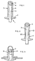
- Figure 1 shows a mandrel 1 having a mandrel head 2, a pulling stem 3 and a breakneck portion 4 intermediate the head 2 and the stem 3. Except for the mandrel head 2 and the breakneck portion 4, the pulling stem is of substantially uniform diameter.
- a rivet sleeve 5 Onto the mandrel has been extruded a rivet sleeve 5.
- the sleeve 5 is preferably formed of aluminium, or an alloy thereof.
- the sleeve 5 is formed having a body portion 6 and a flange 7. The body portion is of substantially uniform diameter along its length. Since the sleeve has been extruded onto the mandrel, the inside of the sleeve is in intimate contact with the mandrel, even filling the breakneck portion 4 of the mandrel.
- the rivet assembly is then rolled at two places 10,11.
- the rolling causes the formation of grooves, causing the rivet body to move away from the mandrel at a position 20 between the grooves.
- the rolling at the grooves also raises the work hardening of the sleeve material at these points.
- the rivet assembly can now be supplied for use.
- the axial pressure causes the rivet body between the grooves to bulge further.
- deformation of the rivet body occurs first between the work hardened grooves during setting of the rivet assembly.
Landscapes
- Engineering & Computer Science (AREA)
- General Engineering & Computer Science (AREA)
- Mechanical Engineering (AREA)
- Insertion Pins And Rivets (AREA)
Claims (4)
- Endverschlossene Nietvorrichtung umfassend einen Dorn (1) mit einen Domkopf (2), einem Bruchhalsabschnitt (4) und einem Zugstamm (3); und eine über den Dorn extrudierte Niethülse (5), die ein erstes geschlossenes Ende und ein zweites geschlossenes Ende aufweist, von dem aus sich ein Flansch (7) erstreckt, mindestens zwei radiale Nute (10, 11), die auf der Niethülse (5) gebildet sind, und ein zwischen der Niethülse und dem Dorn geformter Zwischenraum (20) zwischen den Nuten, dadurch gekennzeichnet, dass die Hülse sich zwischen den zwei Nuten auswärts ausbuchtet, um zwischen den Nuten den Zwischenraum zwischen der Niethülse und dem Dorn zu bilden.
- Endverschlossene Nietvorrichtung nach Anspruch 1, dadurch gekennzeichnet, dass eine Innenoberfläche der Niethülse (5) in engem Kontakt mit dem Bruchhalsabschnitt (4) des Dorns (1) ist.
- Verfahren zur Herstellung einer endverschlossenen Nietvorrichtung, wobei es folgende Schritte umfasst:a) Einsatz eines Dorns (1) mit einem Dornkopf (2), einem Bruchhalsabschmitt (4) und einem Zugstamm (3);b) Extrudieren einer Hülse (5) über den Dorn (1), so dass das Innere der Hülse (5) in engem Kontakt mit dem Dorn (1) ist, umfassend den Bruchhalsabschnitt (4) des Dorns (1);c) Bildung eines Flansches auf der Hülse; undd) Bildung von mindestens zwei Nuten auf der Hülse, was die Hülse (5) des Niets dazu bringt, sich auswärts auszubuchten, um zwischen den Nuten (10, 11) einen Zwischenraum zwischen der Hülse (5) und dem Dom (1) zu bilden.
- Endverschlossene Nietvorrichtung, die gemäß dem Verfahren nach Anspruch 3 hergestellt ist.
Applications Claiming Priority (2)
| Application Number | Priority Date | Filing Date | Title |
|---|---|---|---|
| GB9519475 | 1995-09-23 | ||
| GBGB9519475.9A GB9519475D0 (en) | 1995-09-23 | 1995-09-23 | Blind rivet assembly |
Publications (2)
| Publication Number | Publication Date |
|---|---|
| EP0766012A1 EP0766012A1 (de) | 1997-04-02 |
| EP0766012B1 true EP0766012B1 (de) | 2001-11-28 |
Family
ID=10781190
Family Applications (1)
| Application Number | Title | Priority Date | Filing Date |
|---|---|---|---|
| EP19960306577 Expired - Lifetime EP0766012B1 (de) | 1995-09-23 | 1996-09-10 | Blindniet |
Country Status (3)
| Country | Link |
|---|---|
| EP (1) | EP0766012B1 (de) |
| DE (1) | DE69617353T2 (de) |
| GB (1) | GB9519475D0 (de) |
Families Citing this family (7)
| Publication number | Priority date | Publication date | Assignee | Title |
|---|---|---|---|---|
| GB2357129A (en) * | 1999-12-08 | 2001-06-13 | Emhart Inc | Blind rivet with indentations |
| ATE467056T1 (de) * | 2000-03-29 | 2010-05-15 | Adolf Wuerth Gmbh & Co Kg | Blindniet, nietdorn, halteeinrichtung, verfahren zur herstellung eines blindniets und verfahren zur durchführung einer nietverbindung |
| US7198444B2 (en) * | 2002-05-22 | 2007-04-03 | Newfrey Llc | Multi-grip blind rivet |
| DE102007042190A1 (de) * | 2007-08-28 | 2009-03-05 | Adolf Würth GmbH & Co. KG | Blindniet und Nietdorn |
| JP6048733B2 (ja) * | 2012-10-31 | 2016-12-21 | ポップリベット・ファスナー株式会社 | ブラインドリベット及びそれを使用した封止構造 |
| DE102015100424A1 (de) * | 2015-01-13 | 2016-07-14 | Newfrey Llc | Verfahren zur Herstellung eines endverschlossenen Blindniets und endverschlossener Blindniet |
| KR102784330B1 (ko) * | 2022-09-29 | 2025-03-21 | 김경진 | 연발식 블라인드 리벳 구조 |
Family Cites Families (6)
| Publication number | Priority date | Publication date | Assignee | Title |
|---|---|---|---|---|
| USRE24363E (en) * | 1951-11-07 | 1957-10-01 | Blind rivet assemblies and method of | |
| US3300798A (en) * | 1964-03-10 | 1967-01-31 | Textron Ind Inc | Blind sealing rivet and method of making the same |
| GB2260585A (en) * | 1991-10-09 | 1993-04-21 | Avdel Systems Ltd | Self-plugging blind rivet |
| DE4343171C2 (de) * | 1993-12-17 | 1996-08-08 | Gesipa Blindniettechnik | Blindniet und Verfahren zu seiner Herstellung |
| GB9403224D0 (en) * | 1994-02-19 | 1994-04-13 | Embart Inc | Blind rivet assembly |
| GB9504095D0 (en) * | 1995-03-01 | 1995-04-19 | Emhart Inc | Improved blind rivet |
-
1995
- 1995-09-23 GB GBGB9519475.9A patent/GB9519475D0/en active Pending
-
1996
- 1996-09-10 DE DE1996617353 patent/DE69617353T2/de not_active Expired - Fee Related
- 1996-09-10 EP EP19960306577 patent/EP0766012B1/de not_active Expired - Lifetime
Also Published As
| Publication number | Publication date |
|---|---|
| GB9519475D0 (en) | 1995-11-22 |
| EP0766012A1 (de) | 1997-04-02 |
| DE69617353T2 (de) | 2002-07-18 |
| DE69617353D1 (de) | 2002-01-10 |
Similar Documents
| Publication | Publication Date | Title |
|---|---|---|
| CA2351467C (en) | Blind fastener | |
| EP0398512B1 (de) | Blindniet | |
| US4168650A (en) | Blind fastener | |
| US5645383A (en) | Blind rivet | |
| US4089247A (en) | Blind fastener | |
| EP0958456B1 (de) | Blindniet und verfahren zu seiner herstellung | |
| US6447399B1 (en) | Method of forming a tubular member | |
| US5044850A (en) | Self plugging blind rivet | |
| JPH05209610A (ja) | ブラインド・リベット | |
| JPH0141846B2 (de) | ||
| KR20040103912A (ko) | 클램프 지지 및 잠금부를 갖춘 블라인드측 헤드를 구비한블라인드 파스너 | |
| US7396287B2 (en) | Blind rivet | |
| EP0677666B1 (de) | Blindniete | |
| KR20140061427A (ko) | 블라인드 리벳 및 공작물 배열 | |
| EP1021260B1 (de) | Blindnieten | |
| EP0766012B1 (de) | Blindniet | |
| EP0691479B1 (de) | Blindnietanordnung | |
| KR20160114178A (ko) | 블라인드 리벳 배열 및 조인트 | |
| GB1604502A (en) | Blind fastener | |
| EP1114936B1 (de) | Blindniet | |
| JPH0861339A (ja) | ブラインドリベット組立体 |
Legal Events
| Date | Code | Title | Description |
|---|---|---|---|
| PUAI | Public reference made under article 153(3) epc to a published international application that has entered the european phase |
Free format text: ORIGINAL CODE: 0009012 |
|
| AK | Designated contracting states |
Kind code of ref document: A1 Designated state(s): DE FR GB |
|
| 17P | Request for examination filed |
Effective date: 19970927 |
|
| 17Q | First examination report despatched |
Effective date: 19990312 |
|
| GRAG | Despatch of communication of intention to grant |
Free format text: ORIGINAL CODE: EPIDOS AGRA |
|
| GRAG | Despatch of communication of intention to grant |
Free format text: ORIGINAL CODE: EPIDOS AGRA |
|
| GRAH | Despatch of communication of intention to grant a patent |
Free format text: ORIGINAL CODE: EPIDOS IGRA |
|
| GRAH | Despatch of communication of intention to grant a patent |
Free format text: ORIGINAL CODE: EPIDOS IGRA |
|
| GRAA | (expected) grant |
Free format text: ORIGINAL CODE: 0009210 |
|
| AK | Designated contracting states |
Kind code of ref document: B1 Designated state(s): DE FR GB |
|
| REG | Reference to a national code |
Ref country code: GB Ref legal event code: IF02 |
|
| REF | Corresponds to: |
Ref document number: 69617353 Country of ref document: DE Date of ref document: 20020110 |
|
| ET | Fr: translation filed | ||
| RAP2 | Party data changed (patent owner data changed or rights of a patent transferred) |
Owner name: EMHART LLC |
|
| PLBE | No opposition filed within time limit |
Free format text: ORIGINAL CODE: 0009261 |
|
| STAA | Information on the status of an ep patent application or granted ep patent |
Free format text: STATUS: NO OPPOSITION FILED WITHIN TIME LIMIT |
|
| 26N | No opposition filed | ||
| PGFP | Annual fee paid to national office [announced via postgrant information from national office to epo] |
Ref country code: FR Payment date: 20060918 Year of fee payment: 11 |
|
| PGFP | Annual fee paid to national office [announced via postgrant information from national office to epo] |
Ref country code: GB Payment date: 20060925 Year of fee payment: 11 |
|
| PGFP | Annual fee paid to national office [announced via postgrant information from national office to epo] |
Ref country code: DE Payment date: 20061031 Year of fee payment: 11 |
|
| REG | Reference to a national code |
Ref country code: FR Ref legal event code: CD |
|
| GBPC | Gb: european patent ceased through non-payment of renewal fee |
Effective date: 20070910 |
|
| PG25 | Lapsed in a contracting state [announced via postgrant information from national office to epo] |
Ref country code: DE Free format text: LAPSE BECAUSE OF NON-PAYMENT OF DUE FEES Effective date: 20080401 |
|
| REG | Reference to a national code |
Ref country code: FR Ref legal event code: ST Effective date: 20080531 |
|
| PG25 | Lapsed in a contracting state [announced via postgrant information from national office to epo] |
Ref country code: FR Free format text: LAPSE BECAUSE OF NON-PAYMENT OF DUE FEES Effective date: 20071001 |
|
| PG25 | Lapsed in a contracting state [announced via postgrant information from national office to epo] |
Ref country code: GB Free format text: LAPSE BECAUSE OF NON-PAYMENT OF DUE FEES Effective date: 20070910 |