EP0766037B1 - Beleuchtungsvorrichtung, die mit einer reduzierten Dicke herstellbar ist, insbesondere Scheinwerfer oder andere äussere Fahrzeuglampe - Google Patents
Beleuchtungsvorrichtung, die mit einer reduzierten Dicke herstellbar ist, insbesondere Scheinwerfer oder andere äussere Fahrzeuglampe Download PDFInfo
- Publication number
- EP0766037B1 EP0766037B1 EP96115489A EP96115489A EP0766037B1 EP 0766037 B1 EP0766037 B1 EP 0766037B1 EP 96115489 A EP96115489 A EP 96115489A EP 96115489 A EP96115489 A EP 96115489A EP 0766037 B1 EP0766037 B1 EP 0766037B1
- Authority
- EP
- European Patent Office
- Prior art keywords
- lighting device
- reflector
- reliefs
- modifier
- extractor
- Prior art date
- Legal status (The legal status is an assumption and is not a legal conclusion. Google has not performed a legal analysis and makes no representation as to the accuracy of the status listed.)
- Expired - Lifetime
Links
- 238000009826 distribution Methods 0.000 claims description 13
- 239000003607 modifier Substances 0.000 claims description 13
- 230000003287 optical effect Effects 0.000 description 10
- 238000005286 illumination Methods 0.000 description 5
- 238000004519 manufacturing process Methods 0.000 description 3
- 238000000465 moulding Methods 0.000 description 3
- 239000000853 adhesive Substances 0.000 description 2
- 230000001070 adhesive effect Effects 0.000 description 2
- 230000001427 coherent effect Effects 0.000 description 2
- 238000000034 method Methods 0.000 description 2
- 238000004026 adhesive bonding Methods 0.000 description 1
- 239000011248 coating agent Substances 0.000 description 1
- 238000000576 coating method Methods 0.000 description 1
- 238000010276 construction Methods 0.000 description 1
- 238000005520 cutting process Methods 0.000 description 1
- 238000000605 extraction Methods 0.000 description 1
- 239000012530 fluid Substances 0.000 description 1
- 229910052736 halogen Inorganic materials 0.000 description 1
- 150000002367 halogens Chemical class 0.000 description 1
- 229910052754 neon Inorganic materials 0.000 description 1
- GKAOGPIIYCISHV-UHFFFAOYSA-N neon atom Chemical compound [Ne] GKAOGPIIYCISHV-UHFFFAOYSA-N 0.000 description 1
- 239000013307 optical fiber Substances 0.000 description 1
- 239000000088 plastic resin Substances 0.000 description 1
- 229920000642 polymer Polymers 0.000 description 1
Images

Classifications
-
- F—MECHANICAL ENGINEERING; LIGHTING; HEATING; WEAPONS; BLASTING
- F21—LIGHTING
- F21V—FUNCTIONAL FEATURES OR DETAILS OF LIGHTING DEVICES OR SYSTEMS THEREOF; STRUCTURAL COMBINATIONS OF LIGHTING DEVICES WITH OTHER ARTICLES, NOT OTHERWISE PROVIDED FOR
- F21V5/00—Refractors for light sources
- F21V5/002—Refractors for light sources using microoptical elements for redirecting or diffusing light
-
- F—MECHANICAL ENGINEERING; LIGHTING; HEATING; WEAPONS; BLASTING
- F21—LIGHTING
- F21S—NON-PORTABLE LIGHTING DEVICES; SYSTEMS THEREOF; VEHICLE LIGHTING DEVICES SPECIALLY ADAPTED FOR VEHICLE EXTERIORS
- F21S41/00—Illuminating devices specially adapted for vehicle exteriors, e.g. headlamps
- F21S41/30—Illuminating devices specially adapted for vehicle exteriors, e.g. headlamps characterised by reflectors
- F21S41/32—Optical layout thereof
- F21S41/33—Multi-surface reflectors, e.g. reflectors with facets or reflectors with portions of different curvature
- F21S41/337—Multi-surface reflectors, e.g. reflectors with facets or reflectors with portions of different curvature the reflector having a structured surface, e.g. with facets or corrugations
-
- F—MECHANICAL ENGINEERING; LIGHTING; HEATING; WEAPONS; BLASTING
- F21—LIGHTING
- F21S—NON-PORTABLE LIGHTING DEVICES; SYSTEMS THEREOF; VEHICLE LIGHTING DEVICES SPECIALLY ADAPTED FOR VEHICLE EXTERIORS
- F21S41/00—Illuminating devices specially adapted for vehicle exteriors, e.g. headlamps
- F21S41/30—Illuminating devices specially adapted for vehicle exteriors, e.g. headlamps characterised by reflectors
- F21S41/32—Optical layout thereof
- F21S41/36—Combinations of two or more separate reflectors
- F21S41/365—Combinations of two or more separate reflectors successively reflecting the light
-
- F—MECHANICAL ENGINEERING; LIGHTING; HEATING; WEAPONS; BLASTING
- F21—LIGHTING
- F21S—NON-PORTABLE LIGHTING DEVICES; SYSTEMS THEREOF; VEHICLE LIGHTING DEVICES SPECIALLY ADAPTED FOR VEHICLE EXTERIORS
- F21S43/00—Signalling devices specially adapted for vehicle exteriors, e.g. brake lamps, direction indicator lights or reversing lights
- F21S43/20—Signalling devices specially adapted for vehicle exteriors, e.g. brake lamps, direction indicator lights or reversing lights characterised by refractors, transparent cover plates, light guides or filters
- F21S43/26—Refractors, transparent cover plates, light guides or filters not provided in groups F21S43/235 - F21S43/255
-
- F—MECHANICAL ENGINEERING; LIGHTING; HEATING; WEAPONS; BLASTING
- F21—LIGHTING
- F21S—NON-PORTABLE LIGHTING DEVICES; SYSTEMS THEREOF; VEHICLE LIGHTING DEVICES SPECIALLY ADAPTED FOR VEHICLE EXTERIORS
- F21S43/00—Signalling devices specially adapted for vehicle exteriors, e.g. brake lamps, direction indicator lights or reversing lights
- F21S43/30—Signalling devices specially adapted for vehicle exteriors, e.g. brake lamps, direction indicator lights or reversing lights characterised by reflectors
Definitions
- the present invention relates to a lighting device that can be constructed in such a way that its thickness, that is, its space requirement in terms of depth, is much less than its other dimensions, especially than the surface area of the lens.
- a lighting device is useful as a headlamp or other external vehicle lamp.
- lighting devices in many automotive applications such as headlamps and/or other external lamps, require high power, good optical distribution of the light beam, low power consumption and small size, especially in the direction of depth, that is, parallel with the optical axis of propagation of the final light beam that is to be produced.
- US Patent 5,046,805 relates to a device in which the light beam emitted by the source, transversely to the direction in which it is to be aimed, is collected by a lightguide along which the beam is transmitted by internal reflection and from which it is extracted at the desired points by means of scatterers; while Italian Patent Application No.
- TO94A000773 by the present Applicant discloses a device in which the light beam is collected by a lightguide defined by two mouldings presenting a plurality of appropriately angled interfaces along which the two mouldings, which are transparent, are glued by means of a layer of optical adhesive with a defined refractive index: in this way the propagation of the light beam along the guide produces, as it passes each interface, phenomena of partial refraction/reflection by means of which the light is extracted and guided.
- Both the devices described therefore employ a lightguide as a modifier/extractor of the desired beam.
- the first device in accordance with the cited US patent, gives excellent uniformity of illumination of the guide, but allows no control over the distribution of the light intensity and divergence of the final beam output by the device: such control is necessary in the case of automotive devices.
- These functions must therefore be handled, where possible, by the lens, so that manufacture is made more complex and the space requirement increased.
- the efficiency of the lightguide can be shown to be very low: efficiency is a function of the number of interfaces and only if this number is large enough (greater than 100) is it possible to achieve more than 45% efficient extraction of the light.
- efficiency is a function of the number of interfaces and only if this number is large enough (greater than 100) is it possible to achieve more than 45% efficient extraction of the light.
- the possibility of using a large number of interfaces is limited by the physical dimensions available to the lightguide, which will be small if the space requirements of the device are to be kept down.
- the small dimensions of the final device are therefore achieved at the cost of light efficiency, making it necessary to use high-power lamps and/or a large number of lamps, which in turn means heavy power consumption.
- uniformity of illumination is inversely proportional to the number of interfaces.
- the guides must be inefficient, or alternatively the reflective/refractive characteristics of each interface of the guides must be modified. This can be done either by having different dimensions for each succeeding interface, or by modifying the refractive index of the adhesive between them; however, either method introduces a complication into the manufacturing process and the problem in question is not always satisfactorily solved.
- EP-A-0 364 228 also does not solve the described drawbacks.
- the invention therefore provides a lighting device, usable as a headlamp or other external vehicle lamp, whose thickness is less than its other dimensions, as defined in claim 1.
- the surfaces defining the oblique sides of the reliefs are given diffractive optics or microoptics, either formed directly on these surfaces or applied to them; these diffractive microoptics may optionally be formed directly on a surface of the second reflector that has no reliefs, instead of part of the sawtooth reliefs themselves.
- the lens is preferably provided with a plurality of refractive, diffractive or hybrid diffractive/refractive lenses/microlenses for receiving the light beam after the second reflector has modified and deflected it and giving it a desired definitive distribution.
- the numeral 10 is a general reference for a lighting device, in the present case a headlamp or other external vehicle lamp, that basically comprises an envelope 2 of known type, illustrated only schematically for simplicity's sake, of, for example, parallelepipedal shape and containing a light source 1 and a reflector 3, of for example parabolic profile; the envelope 2 is closed on the outside (sealed against the ingress of fluids, for example) by a transparent screen or lens 6 (Fig. 1).
- a lighting device in the present case a headlamp or other external vehicle lamp
- an envelope 2 of known type, illustrated only schematically for simplicity's sake, of, for example, parallelepipedal shape and containing a light source 1 and a reflector 3, of for example parabolic profile
- the envelope 2 is closed on the outside (sealed against the ingress of fluids, for example) by a transparent screen or lens 6 (Fig. 1).
- the thickness S of the device 10 measured parallel to an optical axis A along which the rays 11 produced by the device 10 are directed is much smaller (for example by an order of magnitude) than the length L of the envelope 2, whereas it may be of any width, meaning its dimension perpendicular to the length L and to the thickness S, depending on what the lighting requirements are.
- the reflector 3, and the source 1, are arranged at one end 4 of the envelope 2, in such a way that the reflector 3 collimates the various light rays 9 emitted by the source 1 and directs them, parallel to each other, along a direction of propagation X - indicated by the arrow in Figure 1 and parallel with the lens 6 and with the side of dimension L of the envelope 2 - perpendicularly and on one side of the optical axis A.
- the envelope 2 also houses a modifier/extractor component, the function of which is to collect the rays 9 collimated by the reflector 3 and deflect them; with defined divergence and intensity with respect to the optical axis A through the lens 6, to form the rays 11 of the final light beam which it is desired to obtain.
- this modifier/extractor component consists of a second reflector 13 facing the reflector 3, opposite from it and in front of the lens 6, for the entire length L of the envelope 2.
- the reflector 13 has a completely reflective upper surface 14 directly facing the lens 6 and arranged obliquely to the direction X of propagation of the beam of rays 9.
- the reflector 13 is consequently basically wedge-shaped in cross section (cutting in direction X).
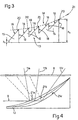
- the surface 14 is defined, wholly or at least in part, by a plurality of mutually adjacent reliefs 15, each of which has, in the direction X of propagation of the light beam collimated by the reflector 3, a sawtooth profile ( Figures 3 and 5); each relief 15 ( Figures 3 and 5) is therefore defined by an oblique side 16, turned towards the light source 1 and lying at a defined angle relative to the direction of propagation X, and by an opposite side 18 situated approximately perpendicularly to the lens 6.
- Both sides 16, 18 are defined, in the present example, by reflective surfaces. These surfaces may be planar, as illustrated, or may be curved, either in direction X or at right angles to this direction, the curvature being described by a single equation or, if required, by a series of different equations (complex surface), in order to control the divergence of the beam of rays 11 leaving the device 10 in the two directions perpendicular to the optical axis A.
- the reliefs 15 are so shaped that respective peaks 20 of said sawtooth teeth all lie on a continuous curved profile of defined shape, illustrated by a dashed line marked 21 in Figure 3.
- the profile 21 is such as to give the reflective surface 14 as a whole a generally concave configuration made up of all the mutually adjacent reliefs 15 put together and, depending on how the final beam of rays 11 is to be distributed and deflected through the lens 6, this profile 21 may have a single equation (may for example be parabolic or elliptical) or, preferably, be a complex profile made up of a plurality of curves of different equations (for example a parabola, a portion of an ellipse, a portion of a circle, a portion of a hyperbole, etc.) fitted together without discontinuities up to a defined order of derivative, preferably to the second order.
- the profile 21 is chosen by calculation, in such a way as to find the best possible compromise between the following requirements:
- Figure 4 illustrates, though not in scale, three different possible profiles 21a, 21b and 21c and shows how the same ray 9 collimated by the reflector 3 is reflected at different angles by each profile 21, thus producing outgoing rays 11a, 11b and 11c having different divergences and striking the lens 6 at quite different points.
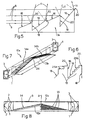
- the teeth or reliefs 15 are all of the same profile, so that the oblique sides 16 all have the same inclination, or, in the variant illustrated in Figure 5, the reflective surface 14 of the reflector, marked 13a, is composed of reliefs 15 whose profiles differ from each other, so that the oblique sides 16 have different inclinations, in order to modify the light distribution (as is indicated by the differing divergences of the resulting outgoing rays 11) without altering the uniformity of illumination of the lens 6.
- the reliefs 15, especially the surfaces defining their oblique sides 16, can be provided with diffractive optics or microoptics 25a and 25b, different from each other (or identical to each other), their function being the initial distribution of the desired final light beam.
- These optics 25a, 25b may be formed directly on the surfaces 16, as a series of microreliefs produced directly along with the component 13, which is preferably a moulding in a synthetic plastic resin, or be made, by a known technique, on respective transparent films (known and not shown), which in turn are applied to the surfaces 16 as a coating, for example by adhesive bonding.
- these may in some cases completely replace some of the sawtooth reliefs 15: in other words, in this case, some areas of the surface 14 have no reliefs 15 and only a diffractive optic. Either way, these surface 14 areas must still lie on the overall profile 21 defining the shape of the surface 14 as a whole.
- the lens 6 is provided with a plurality of refractive, diffractive or hybrid diffractive/refractive lenses/microlenses 6a ( Figure 1) for receiving the light beam after the surface 14 has modified and deflected it, and giving it the desired definitive distribution.
- These optics 6a may likewise be formed directly on the lens 6, or on films which are then adhesively bonded to the lens 6, for example on the inside of the device 10.
- the light source 1 may be of any type capable of emitting monochromatic, polychromatic, coherent, partially coherent or totally incoherent light; for instance, it may be a filament (incandescent), gas, ion-discharge, solid-state polymer, LED (optionally with suitable collimating lenses), halogen or neon lamp, or may consist of an optical fibre; if it is wished not to use the direct rays, moreover, the source 1 can be masked, as known, by a concealing shield arranged near the second reflector 13.
- FIG. 1 and 2 uses a single source of light 1 arranged at one end 4 of the device 10; however, on the basis of the available space and of the power needed to produce the desired final light beam, many other embodiments of the device 10 are possible, two of which, marked 10a and 10b, are illustrated in Figures 7 and 8, as alternatives using more light sources.
- Figure 7 shows a device 10a of elongate shape comprising a pair of opposing in-line reflectors 3, each provided with its own light source 1, and a modifier/extractor consisting of another reflector 13b in the shape of a double wedge arranged between and in line with the two reflectors 3, and defined by a pair of oblique reflective upper surfaces 14a and 14b, whose inclinations are opposite and which each face a reflector 2 and are each defined by a plurality of adjacent reliefs 15, which diminish away from a common middle top portion 34 towards the respective reflectors 3.
- this variant, and also the previous one, as shown in Figures 1 and 2 can serve as an infinitely replicable module along the. direction perpendicular to the side L, in which the sources 1 are arranged in succession on the same side (or on the two opposite sides).
- a device 10c according to the invention can also be made with circular symmetry about the optical axis A: the device 10c in this case comprises a reflector 13c defined by a reflective upper surface 14 of generally conical form, formed by a plurality of annular reliefs 15, each having a sawtooth profile in the radial direction; this reflector 13c, arranged so that its axis is on the optical axis A, is arranged inside a suitable envelope 2 together with a plurality of reflectors 3, each having its own light source 1, disposed radially in a ring around the reflector 13c; at the front, the device 10c is closed by a lens 6. In this way, essentially the same operational configuration is reproduced in any radial direction defined by the axis of a reflector 3 as that of the device 10 of Figures 1 and 2.
Landscapes
- Engineering & Computer Science (AREA)
- General Engineering & Computer Science (AREA)
- Non-Portable Lighting Devices Or Systems Thereof (AREA)
Claims (11)
- Beleuchtungsvorrichtung (10), die als ein Scheinwerfer oder eine andere Fahrzeugaußenleuchte verwendet werden kann und deren Dicke kleiner als ihre anderen Abmessungen ist, umfassend:wobei die Modifizierungs-/Extraktionseinrichtung (13) so beschaffen ist, daß sie den Strahl durch die Linse (6) lenkt;wenigstens eine Lichtquelle (1);eine Modifizierungs-/Extraktionseinrichtung (13);wenigstens einen Reflektor (3) zum Richten eines Lichtstrahls (X) von der Quelle (1) zur Modifizierungs-/Extraktionseinrichtung (13);und eine Linse (6), die im wesentlichen parallel zur Ausbreitungsrichtung des Strahls und vor der Modifizierungs-/Extraktionseinrichtung (13) angeordnet ist,
und wobei die Modifizierungs-/Extraktionseinrichtung ein zweiter Reflektor (13) ist, der dem ersten zugewandt ist, wobei die obere Oberfläche des zweiten Reflektors (13) die der Linse (6) direkt zugewandt ist, schräg zur Ausbreitungsrichtung des Strahls angeordnet ist, wobei die obere Oberfläche wenigstens teilweise durch mehrere zueinander benachbarte Reliefs (15) definiert ist, wobei jedes Relief (15) in der Ausbreitungsrichtung des Strahls (X) ein Sägezahnprofil aufweist, das durch eine schräge Seite (16), die zur Lichtquelle (1) geneigt ist und in einem individuell definierten Winkel zur Ausbreitungsrichtung (X) des Strahls liegt, wobei die obere Oberfläche derart ist, daß alle (Sägezahn-) Profile (15) auf einem durchgehenden gekrümmten Profil mit definierter Form liegen, dadurch gekennzeichnet, daß in Kombination(i) jedes Sägezahnprofil ferner durch eine gegenüberliegende Seite (18) definiert ist, die senkrecht zur Linse (6) angeordnet ist, und(ii) die schrägen Seiten (16) der Reliefs (15) Mittel umfassen, durch die die Modifizierungs-/Extraktionseinrichtung die Divergenz und die Intensitätsverteilung des Strahls steuem kann. - Beleuchtungsvorrichtung (10) nach Anspruch 1, dadurch gekennzeichnet, daß das Profil ein komplexes Profil ist, das aus mehreren Krümmungen mit unterschiedlichen Gleichungen aufgebaut ist, die bis zu einer definierten Ordnung der Ableitung ohne Unstetigkeit zusammengefügt sind.
- Beleuchtungsvorrichtung (10) nach Anspruch 2, dadurch gekennzeichnet, daß die definierte Ordnung der Ableitung die zweite Ordnung ist
- Beleuchtungsvorrichtung (10) nach einem der vorhergehenden Ansprüche, dadurch gekennzeichnet, daß die schrägen Seiten der Reliefs (15) jeweils durch ebene Oberflächen definiert sind.
- Beleuchtungsvorrichtung (10) nach einem der Ansprüche 1 bis 3, dadurch gekennzeichnet, daß die schrägen Seiten der Reliefs (15) jeweils durch gekrümmte Oberflächen definiert sind, wobei die Mittel, durch die die Modifizierungs-/Extraktionseinrichtung (13) die Divergenz und die Intensitätsverteilung des Strahls steuem kann, die gekrümmten Oberflächen umfassen.
- Beleuchtungsvorrichtung (10) nach einem der vorhergehenden Ansprüche, dadurch gekennzeichnet, daß alle Reliefs (15) ein konstantes Profil besitzen, wobei alle schrägen Seiten (16) denselben Winkel zur Ausbreitungsrichtung (X) des Strahls aufweisen.
- Beleuchtungsvorrichtung (10) nach einem der Ansprüche 1 bis 5, dadurch gekennzeichnet, daß sich die Profile (15) untereinander unterscheiden, wobei die schrägen Seiten (16) unterschiedliche Winkel zur Ausbreitungsrichtung (X) des Strahls aufweisen, wobei die Mittel, durch die die Modifizierungs-/Extraktionseinrichtung (13) die Divergenz und die Intensrtätsverteilung des Strahls steuem kann, die unterschiedlichen Winkel umfassen.
- Beleuchtungsvorrichtung (10) nach einem der vorhergehenden Ansprüche, dadurch gekennzeichnet, daß wenigstens die Oberflächen, die die schrägen Seiten (16) der Reliefs (15) definieren, lichtbeugende Optikeinrichtungen oder Mikrooptikeinrichtungen (15a, 25b) sind, die entweder direkt auf diesen Oberflächen ausgebildet sind oder auf diese aufgebracht sind, wobei die Mittel, durch die die Modifizierungs-/Extraktionseinrichtung (13) die Divergenz und die Intensitätsverteilung des Strahls steuern kann, die lichtbeugenden Optikeinrichtungen (25a, 25b) umfassen.
- Beleuchtungsvorrichtung (10) nach einem der vorhergehenden Ansprüche, dadurch gekennzeichnet, daß die Linse (6) mit mehreren brechenden, lichtbeugenden oder brechenden/lichtbeugenden Hybrid-Linsen/-Mikrolinsen (6a) versehen ist, die den Lichtstrahl empfangen, nachdem der zweite Reflektor (13) ihn modifiziert und abgelenkt und ihm eine gewünschte endgültige Verteilung verliehen hat.
- Beleuchtungsvorrichtung (10a) nach einem der vorhergehenden Ansprüche, dadurch gekennzeichnet, daß sie eine längliche Form besitzt und ein Paar erster gegenüberliegender In-line-Reflektoren (3), von denen jeder mit seiner eigenen Lichtquelle versehen ist, und einen zweiten Reflektor (13b) in Form eines Doppelkeils umfaßt, der zwischen den ersten Reflektoren (3) und mit diesen in Reihe angeordnet und durch ein Paar schräger reflektierender oberer Oberflächen (14a, 14b) definiert ist, wovon jede einem ersten Reflektor zugewandt und durch mehrere benachbarte Reliefs (15) definiert ist, die von einem gemeinsamen mittleren Spitzenabschnitt weg zum ersten Reflektor kleiner werden.
- Beteuchtungsvorrichtung (10c) nach einem der vorhergehenden Ansprüche, dadurch gekennzeichnet, daß sie im rechten Winkel zur Ausbreitungsrichtung des von ihr ausgesendeten Lichtstrahls eine im allgemeinen kreisförmige Form aufweist und einen zweiten Reflektor (13c), der durch eine reflektierende obere Oberfläche definiert ist, die durch mehrere kreisförmige Reliefs (15) gebildet ist, die jeweils in der radialen Richtung ein Sägezahnprofil aufweisen, und mehrere erste Reflektoren (3) umfaßt, die jeweils ihre eigene Lichtquelle (1) aufweisen, die radial in einem Ring um den zweiten Reflektor (13c) angeordnet ist.
Applications Claiming Priority (2)
| Application Number | Priority Date | Filing Date | Title |
|---|---|---|---|
| IT95TO000771A IT1281366B1 (it) | 1995-09-27 | 1995-09-27 | Dispositivo di illuminazione realizzabile con spessore ridotto, in particolare proiettore o fanale per veicoli |
| ITTO950771 | 1995-09-27 |
Publications (2)
| Publication Number | Publication Date |
|---|---|
| EP0766037A1 EP0766037A1 (de) | 1997-04-02 |
| EP0766037B1 true EP0766037B1 (de) | 2003-02-05 |
Family
ID=11413838
Family Applications (1)
| Application Number | Title | Priority Date | Filing Date |
|---|---|---|---|
| EP96115489A Expired - Lifetime EP0766037B1 (de) | 1995-09-27 | 1996-09-26 | Beleuchtungsvorrichtung, die mit einer reduzierten Dicke herstellbar ist, insbesondere Scheinwerfer oder andere äussere Fahrzeuglampe |
Country Status (4)
| Country | Link |
|---|---|
| EP (1) | EP0766037B1 (de) |
| DE (1) | DE69626078T2 (de) |
| ES (1) | ES2189846T3 (de) |
| IT (1) | IT1281366B1 (de) |
Cited By (2)
| Publication number | Priority date | Publication date | Assignee | Title |
|---|---|---|---|---|
| WO2009100560A1 (zh) * | 2008-01-31 | 2009-08-20 | Dingguo Pan | 变截面不等边直角三角形棱镜圆盘形反光板和用它制成的灯具 |
| WO2010022540A1 (zh) * | 2008-08-26 | 2010-03-04 | Pan Dingguo | 反光片及包含它的片灯、片灯具 |
Families Citing this family (28)
| Publication number | Priority date | Publication date | Assignee | Title |
|---|---|---|---|---|
| IT1292782B1 (it) * | 1997-06-19 | 1999-02-11 | Fiat Ricerche | Fanale per autoveicoli. |
| WO1999000623A1 (en) * | 1997-06-30 | 1999-01-07 | Donnelly Corporation | Automotive lamp lens and lamp system utilizing diffractive optics and method for making the same |
| DE19803518A1 (de) | 1998-01-30 | 1999-08-05 | Hella Kg Hueck & Co | Stabförmiger Lichtleiter |
| JP2960928B1 (ja) * | 1998-07-24 | 1999-10-12 | スタンレー電気株式会社 | 車両用信号灯具 |
| DE69900437T2 (de) | 1999-08-11 | 2002-05-16 | Automotive Lighting Italia S.P.A., Venaria Reale | Kraftfahrzeugleuchte |
| JP4010084B2 (ja) * | 1999-10-21 | 2007-11-21 | 市光工業株式会社 | 小型光源モジュール及び光源ユニット |
| IT1320063B1 (it) * | 2000-05-02 | 2003-11-12 | Fiat Ricerche | Dispositivo di illuminazione. |
| DE10022779A1 (de) * | 2000-05-10 | 2001-11-15 | Hella Kg Hueck & Co | Stabförmiger Lichtleiter |
| DE10022780A1 (de) * | 2000-05-10 | 2001-11-15 | Hella Kg Hueck & Co | Stabförmiger Lichtleiter |
| DE10153380A1 (de) * | 2000-11-29 | 2002-06-13 | Zumtobel Staff Gmbh | Leuchte mit einer lichtdurchlässigen Scheibe |
| ITTO20010461A1 (it) * | 2001-05-18 | 2002-11-18 | Fiat Ricerche | Dispositivo di illuminazione, particolarmente fanale per autoveicoli o luce di emergenza. |
| DE10143415A1 (de) | 2001-09-05 | 2003-03-20 | Automotive Lighting Reutlingen | Leuchtenanordnung |
| DE10247980B4 (de) * | 2002-10-15 | 2011-05-26 | Automotive Lighting Reutlingen Gmbh | Fahrzeugleuchte |
| FR2906009B1 (fr) * | 2006-09-19 | 2008-12-26 | Valeo Vision Sa | Dispositif d'eclairage et/ou de signalisation pour vehicule automobile. |
| DE102007020397B8 (de) * | 2007-04-27 | 2012-08-30 | Bombardier Transportation Gmbh | Beleuchtungsvorrichtung für die Beleuchtung von Fahrzeuginnenräumen |
| KR20090063622A (ko) * | 2007-12-14 | 2009-06-18 | 삼성전자주식회사 | 투사형 디스플레이장치 및 그의 디스플레이방법 |
| KR101292481B1 (ko) | 2008-08-26 | 2013-07-31 | 딩구오 판 | 동일한 단면을 구비하는 삼각형에 기초한 프리즘을 구비하는 원형 광 반사판 및 그것을 이용하여 만들어지는 원판형 램프 |
| WO2011134164A1 (zh) * | 2010-04-30 | 2011-11-03 | Pan Dingguo | 微棱镜导光板及其制造方法、及其制成的片灯、片灯具 |
| DE102010051826A1 (de) * | 2010-11-18 | 2012-05-24 | Valeo Schalter Und Sensoren Gmbh | Lichtleiter, insbesondere zum Beleuchten eines Schachtes für einen Datenträger, und Abspielgerät mit einem derartigen Lichtleiter |
| DE102011018508C5 (de) * | 2011-04-23 | 2016-06-30 | Automotive Lighting Reutlingen Gmbh | Lichtleiterelement-Anordnung und Kraftfahrzeugbeleuchtungseinrichtung mit einer solchen Lichtleiterelement-Anordnung |
| WO2013059811A1 (en) * | 2011-10-21 | 2013-04-25 | Energy Focus, Inc. | Efficient side-light distribution system |
| US9380918B2 (en) | 2013-03-11 | 2016-07-05 | Kohler Co. | Toilet with lighted seat hinge |
| CN103175086A (zh) * | 2013-04-07 | 2013-06-26 | 长春鸿德汽车照明有限公司 | 汽车信号灯具led虚拟光源 |
| DE102014212299A1 (de) | 2014-06-26 | 2015-12-31 | Automotive Lighting Reutlingen Gmbh | Lichtleiter-Anordnung zum Einsatz in einer Beleuchtungseinrichtung eines Kraftfahrzeugs und Kraftfahrzeugbeleuchtungseinrichtung mit einer solchen Lichtleiter-Anordnung |
| AT517414A1 (de) * | 2015-06-29 | 2017-01-15 | Zkw Group Gmbh | Lichtleiteranordnung zur Erzeugung von zumindest einer Beleuchtungsfunktion und/oder Signalisierungsfunktion eines Kraftfahrzeugscheinwerfers |
| AT517413B1 (de) * | 2015-06-29 | 2018-07-15 | Zkw Group Gmbh | Lichtleiteranordnung zur Erzeugung von zumindest einer Beleuchtungsfunktion und/oder Signalisierungsfunktion eines Kraftfahrzeugscheinwerfers |
| DE102016117685A1 (de) | 2016-09-20 | 2018-03-22 | HELLA GmbH & Co. KGaA | Beleuchtungsvorrichtung für Fahrzeuge |
| US10194777B2 (en) | 2017-02-06 | 2019-02-05 | Kohler Co. | Toilet seat lighting apparatuses |
Family Cites Families (4)
| Publication number | Priority date | Publication date | Assignee | Title |
|---|---|---|---|---|
| GB1021159A (en) * | 1963-11-18 | 1966-03-02 | Lucas Industries Ltd | Lamps |
| US4713738A (en) * | 1986-08-15 | 1987-12-15 | Davis Charles S | Light fixture using a holographic optical reflector |
| CA1321988C (en) * | 1988-10-11 | 1993-09-07 | Jeffrey J. Melby | Light fixture |
| JPH0714407A (ja) * | 1993-06-24 | 1995-01-17 | Koito Mfg Co Ltd | 車両用灯具 |
-
1995
- 1995-09-27 IT IT95TO000771A patent/IT1281366B1/it active IP Right Grant
-
1996
- 1996-09-26 EP EP96115489A patent/EP0766037B1/de not_active Expired - Lifetime
- 1996-09-26 DE DE69626078T patent/DE69626078T2/de not_active Expired - Fee Related
- 1996-09-26 ES ES96115489T patent/ES2189846T3/es not_active Expired - Lifetime
Cited By (2)
| Publication number | Priority date | Publication date | Assignee | Title |
|---|---|---|---|---|
| WO2009100560A1 (zh) * | 2008-01-31 | 2009-08-20 | Dingguo Pan | 变截面不等边直角三角形棱镜圆盘形反光板和用它制成的灯具 |
| WO2010022540A1 (zh) * | 2008-08-26 | 2010-03-04 | Pan Dingguo | 反光片及包含它的片灯、片灯具 |
Also Published As
| Publication number | Publication date |
|---|---|
| ITTO950771A1 (it) | 1997-03-27 |
| IT1281366B1 (it) | 1998-02-18 |
| DE69626078D1 (de) | 2003-03-13 |
| ITTO950771A0 (it) | 1995-09-27 |
| DE69626078T2 (de) | 2003-11-13 |
| ES2189846T3 (es) | 2003-07-16 |
| EP0766037A1 (de) | 1997-04-02 |
Similar Documents
| Publication | Publication Date | Title |
|---|---|---|
| EP0766037B1 (de) | Beleuchtungsvorrichtung, die mit einer reduzierten Dicke herstellbar ist, insbesondere Scheinwerfer oder andere äussere Fahrzeuglampe | |
| CA2685108C (en) | Illumination device | |
| US5894196A (en) | Angled elliptical axial lighting device | |
| US5894195A (en) | Elliptical axial lighting device | |
| US5835661A (en) | Light expanding system for producing a linear or planar light beam from a point-like light source | |
| US5898267A (en) | Parabolic axial lighting device | |
| US5434754A (en) | Light manifold | |
| EP1567803B1 (de) | Beleuchtungsvorrichtung | |
| EP0704655B1 (de) | Lichtleiter-Beleuchtungssystem zur Herstellung eines dünnen Beleuchtungselements | |
| US20030063473A1 (en) | Lighting of indicating apparatus for a motor vehicle | |
| CN107023796B (zh) | 准直透镜和汽车用光学模组 | |
| EP0846914A1 (de) | Beleuchtungseinrichtung zur Erzeugung eines viereckigen Lichtmusters auf dem beleuchteten Bereich, z.B. zur Beleuchtung von Fussgängerüberwegen | |
| JPS5856920B2 (ja) | 光学式エンコ−ダ用配光装置 | |
| JPWO2015129251A1 (ja) | 照明装置およびその照明装置を搭載した自動車 | |
| TW201428208A (zh) | 用於蝠翼狀光分佈之透鏡反射鏡組合 | |
| US20060274621A1 (en) | Light guiding unit, light guiding unit assembly, and lighting device including the same | |
| EP3861245A1 (de) | Led-beleuchtungsvorrichtung | |
| KR20150076551A (ko) | 광학 부재 및 이를 이용하는 조명 장치 | |
| AU5737499A (en) | Light with a light-guiding element | |
| JP5708991B2 (ja) | 車両用灯具及び車両用灯具に用いられる導光レンズ | |
| US7600894B1 (en) | Luminaires and optics for control and distribution of multiple quasi point source light sources such as LEDs | |
| US20100079995A1 (en) | Luminaires and optics for control and distribution of multiple quasi point source light sources such as leds | |
| CN206330086U (zh) | Led全反射透镜和led线光源 | |
| CN121666507A (zh) | 用于车辆的灯具 | |
| WO2025139003A1 (zh) | 一种车灯光学元件、车灯模组和车辆 |
Legal Events
| Date | Code | Title | Description |
|---|---|---|---|
| PUAI | Public reference made under article 153(3) epc to a published international application that has entered the european phase |
Free format text: ORIGINAL CODE: 0009012 |
|
| AK | Designated contracting states |
Kind code of ref document: A1 Designated state(s): DE ES FR GB SE |
|
| 17P | Request for examination filed |
Effective date: 19970228 |
|
| RAP1 | Party data changed (applicant data changed or rights of an application transferred) |
Owner name: AUTOMOTIVE LIGHTING ITALIA SPA |
|
| 17Q | First examination report despatched |
Effective date: 20010124 |
|
| RIC1 | Information provided on ipc code assigned before grant |
Free format text: 7F 21V 7/00 A, 7F 21S 8/10 B |
|
| RIC1 | Information provided on ipc code assigned before grant |
Free format text: 7F 21V 7/00 A, 7F 21S 8/10 B |
|
| GRAH | Despatch of communication of intention to grant a patent |
Free format text: ORIGINAL CODE: EPIDOS IGRA |
|
| GRAH | Despatch of communication of intention to grant a patent |
Free format text: ORIGINAL CODE: EPIDOS IGRA |
|
| GRAA | (expected) grant |
Free format text: ORIGINAL CODE: 0009210 |
|
| AK | Designated contracting states |
Designated state(s): DE ES FR GB SE |
|
| REG | Reference to a national code |
Ref country code: GB Ref legal event code: FG4D |
|
| REF | Corresponds to: |
Ref document number: 69626078 Country of ref document: DE Date of ref document: 20030313 Kind code of ref document: P |
|
| PG25 | Lapsed in a contracting state [announced via postgrant information from national office to epo] |
Ref country code: SE Free format text: LAPSE BECAUSE OF FAILURE TO SUBMIT A TRANSLATION OF THE DESCRIPTION OR TO PAY THE FEE WITHIN THE PRESCRIBED TIME-LIMIT Effective date: 20030505 |
|
| REG | Reference to a national code |
Ref country code: ES Ref legal event code: FG2A Ref document number: 2189846 Country of ref document: ES Kind code of ref document: T3 |
|
| ET | Fr: translation filed | ||
| PG25 | Lapsed in a contracting state [announced via postgrant information from national office to epo] |
Ref country code: GB Free format text: LAPSE BECAUSE OF NON-PAYMENT OF DUE FEES Effective date: 20030926 |
|
| PLBE | No opposition filed within time limit |
Free format text: ORIGINAL CODE: 0009261 |
|
| STAA | Information on the status of an ep patent application or granted ep patent |
Free format text: STATUS: NO OPPOSITION FILED WITHIN TIME LIMIT |
|
| 26N | No opposition filed |
Effective date: 20031106 |
|
| GBPC | Gb: european patent ceased through non-payment of renewal fee |
Effective date: 20030926 |
|
| PGFP | Annual fee paid to national office [announced via postgrant information from national office to epo] |
Ref country code: ES Payment date: 20040927 Year of fee payment: 9 |
|
| PG25 | Lapsed in a contracting state [announced via postgrant information from national office to epo] |
Ref country code: ES Free format text: LAPSE BECAUSE OF NON-PAYMENT OF DUE FEES Effective date: 20050927 |
|
| PGFP | Annual fee paid to national office [announced via postgrant information from national office to epo] |
Ref country code: DE Payment date: 20051117 Year of fee payment: 10 |
|
| REG | Reference to a national code |
Ref country code: ES Ref legal event code: FD2A Effective date: 20050927 |
|
| PG25 | Lapsed in a contracting state [announced via postgrant information from national office to epo] |
Ref country code: DE Free format text: LAPSE BECAUSE OF NON-PAYMENT OF DUE FEES Effective date: 20070403 |
|
| REG | Reference to a national code |
Ref country code: FR Ref legal event code: PLFP Year of fee payment: 20 |
|
| PGFP | Annual fee paid to national office [announced via postgrant information from national office to epo] |
Ref country code: FR Payment date: 20150824 Year of fee payment: 20 |