EP0766045B1 - Arbeitsweise einer Vormischbrennkammer - Google Patents
Arbeitsweise einer Vormischbrennkammer Download PDFInfo
- Publication number
- EP0766045B1 EP0766045B1 EP96116290A EP96116290A EP0766045B1 EP 0766045 B1 EP0766045 B1 EP 0766045B1 EP 96116290 A EP96116290 A EP 96116290A EP 96116290 A EP96116290 A EP 96116290A EP 0766045 B1 EP0766045 B1 EP 0766045B1
- Authority
- EP
- European Patent Office
- Prior art keywords
- fuel
- air
- pilot
- flame
- combustor
- Prior art date
- Legal status (The legal status is an assumption and is not a legal conclusion. Google has not performed a legal analysis and makes no representation as to the accuracy of the status listed.)
- Expired - Lifetime
Links
- 238000000034 method Methods 0.000 title claims description 6
- 239000000446 fuel Substances 0.000 claims description 138
- 238000002485 combustion reaction Methods 0.000 claims description 42
- 239000000203 mixture Substances 0.000 claims description 25
- 239000003570 air Substances 0.000 description 58
- 239000007789 gas Substances 0.000 description 23
- 238000002156 mixing Methods 0.000 description 12
- 238000009792 diffusion process Methods 0.000 description 5
- 230000000153 supplemental effect Effects 0.000 description 5
- 230000015572 biosynthetic process Effects 0.000 description 4
- 238000010304 firing Methods 0.000 description 4
- 238000011144 upstream manufacturing Methods 0.000 description 4
- 230000004888 barrier function Effects 0.000 description 3
- 230000003197 catalytic effect Effects 0.000 description 3
- IJGRMHOSHXDMSA-UHFFFAOYSA-N Atomic nitrogen Chemical compound N#N IJGRMHOSHXDMSA-UHFFFAOYSA-N 0.000 description 2
- KDLHZDBZIXYQEI-UHFFFAOYSA-N Palladium Chemical compound [Pd] KDLHZDBZIXYQEI-UHFFFAOYSA-N 0.000 description 2
- UHZZMRAGKVHANO-UHFFFAOYSA-M chlormequat chloride Chemical compound [Cl-].C[N+](C)(C)CCCl UHZZMRAGKVHANO-UHFFFAOYSA-M 0.000 description 2
- 238000001816 cooling Methods 0.000 description 2
- 230000001965 increasing effect Effects 0.000 description 2
- 238000004519 manufacturing process Methods 0.000 description 2
- 239000000463 material Substances 0.000 description 2
- VNWKTOKETHGBQD-UHFFFAOYSA-N methane Chemical compound C VNWKTOKETHGBQD-UHFFFAOYSA-N 0.000 description 2
- BASFCYQUMIYNBI-UHFFFAOYSA-N platinum Chemical compound [Pt] BASFCYQUMIYNBI-UHFFFAOYSA-N 0.000 description 2
- 238000010793 Steam injection (oil industry) Methods 0.000 description 1
- 230000001154 acute effect Effects 0.000 description 1
- 239000012080 ambient air Substances 0.000 description 1
- 238000004873 anchoring Methods 0.000 description 1
- 238000000576 coating method Methods 0.000 description 1
- 238000010586 diagram Methods 0.000 description 1
- 238000007599 discharging Methods 0.000 description 1
- 230000000694 effects Effects 0.000 description 1
- 239000003344 environmental pollutant Substances 0.000 description 1
- 239000012530 fluid Substances 0.000 description 1
- 238000010438 heat treatment Methods 0.000 description 1
- 230000001939 inductive effect Effects 0.000 description 1
- 239000003345 natural gas Substances 0.000 description 1
- 229910052757 nitrogen Inorganic materials 0.000 description 1
- 229910052763 palladium Inorganic materials 0.000 description 1
- 229910052697 platinum Inorganic materials 0.000 description 1
- 231100000719 pollutant Toxicity 0.000 description 1
- XLYOFNOQVPJJNP-UHFFFAOYSA-N water Substances O XLYOFNOQVPJJNP-UHFFFAOYSA-N 0.000 description 1
Images




Classifications
-
- F—MECHANICAL ENGINEERING; LIGHTING; HEATING; WEAPONS; BLASTING
- F23—COMBUSTION APPARATUS; COMBUSTION PROCESSES
- F23R—GENERATING COMBUSTION PRODUCTS OF HIGH PRESSURE OR HIGH VELOCITY, e.g. GAS-TURBINE COMBUSTION CHAMBERS
- F23R3/00—Continuous combustion chambers using liquid or gaseous fuel
- F23R3/28—Continuous combustion chambers using liquid or gaseous fuel characterised by the fuel supply
- F23R3/34—Feeding into different combustion zones
- F23R3/343—Pilot flames, i.e. fuel nozzles or injectors using only a very small proportion of the total fuel to insure continuous combustion
-
- F—MECHANICAL ENGINEERING; LIGHTING; HEATING; WEAPONS; BLASTING
- F23—COMBUSTION APPARATUS; COMBUSTION PROCESSES
- F23D—BURNERS
- F23D14/00—Burners for combustion of a gas, e.g. of a gas stored under pressure as a liquid
- F23D14/02—Premix gas burners, i.e. in which gaseous fuel is mixed with combustion air upstream of the combustion zone
-
- F—MECHANICAL ENGINEERING; LIGHTING; HEATING; WEAPONS; BLASTING
- F23—COMBUSTION APPARATUS; COMBUSTION PROCESSES
- F23D—BURNERS
- F23D23/00—Assemblies of two or more burners
-
- F—MECHANICAL ENGINEERING; LIGHTING; HEATING; WEAPONS; BLASTING
- F23—COMBUSTION APPARATUS; COMBUSTION PROCESSES
- F23R—GENERATING COMBUSTION PRODUCTS OF HIGH PRESSURE OR HIGH VELOCITY, e.g. GAS-TURBINE COMBUSTION CHAMBERS
- F23R3/00—Continuous combustion chambers using liquid or gaseous fuel
- F23R3/02—Continuous combustion chambers using liquid or gaseous fuel characterised by the air-flow or gas-flow configuration
- F23R3/04—Air inlet arrangements
- F23R3/10—Air inlet arrangements for primary air
-
- F—MECHANICAL ENGINEERING; LIGHTING; HEATING; WEAPONS; BLASTING
- F23—COMBUSTION APPARATUS; COMBUSTION PROCESSES
- F23R—GENERATING COMBUSTION PRODUCTS OF HIGH PRESSURE OR HIGH VELOCITY, e.g. GAS-TURBINE COMBUSTION CHAMBERS
- F23R3/00—Continuous combustion chambers using liquid or gaseous fuel
- F23R3/28—Continuous combustion chambers using liquid or gaseous fuel characterised by the fuel supply
- F23R3/286—Continuous combustion chambers using liquid or gaseous fuel characterised by the fuel supply having fuel-air premixing devices
-
- F—MECHANICAL ENGINEERING; LIGHTING; HEATING; WEAPONS; BLASTING
- F23—COMBUSTION APPARATUS; COMBUSTION PROCESSES
- F23R—GENERATING COMBUSTION PRODUCTS OF HIGH PRESSURE OR HIGH VELOCITY, e.g. GAS-TURBINE COMBUSTION CHAMBERS
- F23R3/00—Continuous combustion chambers using liquid or gaseous fuel
- F23R3/28—Continuous combustion chambers using liquid or gaseous fuel characterised by the fuel supply
- F23R3/34—Feeding into different combustion zones
-
- F—MECHANICAL ENGINEERING; LIGHTING; HEATING; WEAPONS; BLASTING
- F23—COMBUSTION APPARATUS; COMBUSTION PROCESSES
- F23R—GENERATING COMBUSTION PRODUCTS OF HIGH PRESSURE OR HIGH VELOCITY, e.g. GAS-TURBINE COMBUSTION CHAMBERS
- F23R3/00—Continuous combustion chambers using liquid or gaseous fuel
- F23R3/28—Continuous combustion chambers using liquid or gaseous fuel characterised by the fuel supply
- F23R3/34—Feeding into different combustion zones
- F23R3/346—Feeding into different combustion zones for staged combustion
-
- F—MECHANICAL ENGINEERING; LIGHTING; HEATING; WEAPONS; BLASTING
- F23—COMBUSTION APPARATUS; COMBUSTION PROCESSES
- F23R—GENERATING COMBUSTION PRODUCTS OF HIGH PRESSURE OR HIGH VELOCITY, e.g. GAS-TURBINE COMBUSTION CHAMBERS
- F23R3/00—Continuous combustion chambers using liquid or gaseous fuel
- F23R3/40—Continuous combustion chambers using liquid or gaseous fuel characterised by the use of catalytic means
-
- F—MECHANICAL ENGINEERING; LIGHTING; HEATING; WEAPONS; BLASTING
- F23—COMBUSTION APPARATUS; COMBUSTION PROCESSES
- F23D—BURNERS
- F23D2209/00—Safety arrangements
- F23D2209/20—Flame lift-off / stability
-
- F—MECHANICAL ENGINEERING; LIGHTING; HEATING; WEAPONS; BLASTING
- F23—COMBUSTION APPARATUS; COMBUSTION PROCESSES
- F23D—BURNERS
- F23D2900/00—Special features of, or arrangements for burners using fluid fuels or solid fuels suspended in a carrier gas
- F23D2900/00008—Burner assemblies with diffusion and premix modes, i.e. dual mode burners
-
- F—MECHANICAL ENGINEERING; LIGHTING; HEATING; WEAPONS; BLASTING
- F23—COMBUSTION APPARATUS; COMBUSTION PROCESSES
- F23D—BURNERS
- F23D2900/00—Special features of, or arrangements for burners using fluid fuels or solid fuels suspended in a carrier gas
- F23D2900/00014—Pilot burners specially adapted for ignition of main burners in furnaces or gas turbines
-
- F—MECHANICAL ENGINEERING; LIGHTING; HEATING; WEAPONS; BLASTING
- F23—COMBUSTION APPARATUS; COMBUSTION PROCESSES
- F23R—GENERATING COMBUSTION PRODUCTS OF HIGH PRESSURE OR HIGH VELOCITY, e.g. GAS-TURBINE COMBUSTION CHAMBERS
- F23R2900/00—Special features of, or arrangements for continuous combustion chambers; Combustion processes therefor
- F23R2900/00002—Gas turbine combustors adapted for fuels having low heating value [LHV]
-
- Y—GENERAL TAGGING OF NEW TECHNOLOGICAL DEVELOPMENTS; GENERAL TAGGING OF CROSS-SECTIONAL TECHNOLOGIES SPANNING OVER SEVERAL SECTIONS OF THE IPC; TECHNICAL SUBJECTS COVERED BY FORMER USPC CROSS-REFERENCE ART COLLECTIONS [XRACs] AND DIGESTS
- Y02—TECHNOLOGIES OR APPLICATIONS FOR MITIGATION OR ADAPTATION AGAINST CLIMATE CHANGE
- Y02T—CLIMATE CHANGE MITIGATION TECHNOLOGIES RELATED TO TRANSPORTATION
- Y02T50/00—Aeronautics or air transport
- Y02T50/60—Efficient propulsion technologies, e.g. for aircraft
Definitions
- the present invention relates to a method of burning fuel in compressed air as disclosed e.g. in document EP-A-526 152. More specifically, the present invention relates such a method, used in a gas turbine, that significantly reduces the amount of NOx produced by combustion.
- fuel is burned in compressed air, produced by a compressor, in one or more combustors.
- combustors had a primary combustion zone in which an approximately stoichiometric mixture of fuel and air was formed and burned in a diffusion type combustion process. Additional air was introduced into the combustor downstream of the primary combustion zone.
- the overall fuel/air ratio was considerably less than stoichiometric, the fuel/air mixture was readily ignited at start-up and good flame stability was achieved over a wide range in firing temperatures due to the locally richer nature of the fuel/air mixture in the primary combustion zone.
- the invention consists in a method of burning fuel in compressed air, in a gas turbine, comprising the steps of:
- FIG. 1 a gas turbine 1.
- the gas turbine is comprised of a compressor 3 into which ambient air 2 is drawn.
- the compressor 3 discharges compressed air 4 to a combustor 6 in which a fuel 5 is burned to produce a hot gas 7.
- the hot gas 7 is expanded in a turbine 8 and then discharged as exhaust gas 9.
- the current invention concerns the combustor 6 for the gas turbine 1 -- specifically, a combustor designed to generate very low levels of NOx (e.g., less than approximately 9 ppmv when the gas turbine is operating at its base load firing temperature and without the use of water or steam injection).
- the combustor 6 according to the current invention comprises a pre-mixing zone 10, in which air and fuel are mixed, and a combustion zone 12 downstream of the pre-mixing zone.
- Three large window-type openings 30 are equally spaced around the circumference of the housing 27.
- a duct 28 is attached to the aft end of the housing 27 and encloses the combustion zone 12. Cooling passages 31 are formed around the circumference of the duct 28 so as to allow the introduction of film cooling air. An outlet 56 is formed at the aft end of the duct 28 for discharging the hot gas produced in the combustor 6 to the turbine 8.
- the front flange 13 of the housing 27 is mounted onto a plate 14, via screws 15, to facilitate mounting the combustor 6 into the combustion section of the gas turbine 1.
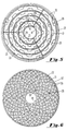
- five cylindrical liners 18-22 are concentrically arranged in the mixing zone 10 of the combustor 6 so as form four annular passages 23-26, one annular passage being formed between each adjacent pair of liners.
- Each of the annular passages has an inlet end 34 and a discharge end 35.
- Support struts 32 are disposed adjacent the inlets 34 of each of the annular passages to strengthen the structure.
- a barrier plate 57 is attached at the aft end of the liners 18-22, adjacent the discharges 35 of the annular passages, and separates the mixing portion 10 of the combustor from the combustion zone 12.
- a plurality of baffles 33 extend both radially inward and outward from the liners 18-22 into the annular passages 23-26 around which the baffles are circumferentially distributed.
- a plurality of swirlers 59 are disposed in the barrier plate 57 so as to be circumferentially distributed around each of the annular passages 23-26 adjacent their discharges 35.
- a typical swirler 59 is shown in Figures 9 and 10 and is comprised of an outer ring from which a plurality of vanes 53 extend.
- the swirler vanes 53 are adapted to impart rotation to the fuel and air flowing through the swirler 59. In so doing, they promote mixing of the fuel and air and cause recirculation that serves to anchor the flame.
- a centrally disposed passage 52 is formed within the swirler 59 that allows fluid to flow through the barrier plate 57 without passing through the swirler vanes 53. By leaving some of the passages 52 open and plugging others, the amount of air flowing through each swirlers 59 can be adjusted to improve stability.
- each of the vanes is comprised of a metallic core 54 that has been coated with a catalytic material 55, such as a palladium and platinum composition, that promotes combustion at low temperatures and, hence, reduces the production of NOx.
- a catalytic material 55 such as a palladium and platinum composition
- Suitable catalytic coatings may be obtained through Precision Combustion, Inc., of New Haven, Connecticut.
- a fuel assembly is disposed in the combustor 6.
- the fuel assembly is comprised of four concentric toroidal manifolds 70-73.
- Each fuel manifold 70-73 is disposed just upstream of the inlet 34 of one of the annular passages 23-26.
- a plurality of rearward facing fuel discharge ports 47 are distributed around the circumference of each of the manifolds 70-73.
- the discharge ports 47 are spaced approximately 2 cm (0.75 inches) apart so that the fuel 5 is evenly distributed around the circumference of the annular passages 23-26.
- each of the fuel discharge ports 47 is oriented at an angle A, as shown in Figure 12, of approximately 18# so that it directs the fuel 5 at an angle into the radially outboard regions of each of the annular passages 23-26, as shown in Figure 4, to promote mixing.
- one of four axially extending fuel supply tubes 74-77 connects to each of the four fuel manifolds 70-73 so that each manifold is supplied with fuel 5 by a separate fuel supply tube.
- a flow control valve 78 is installed in each fuel supply tube 74-77 in order to control the flow of fuel 5 from a fuel supply (not shown) to each fuel supply tube.
- the supply of fuel to each annular passage 23-26 can be separately controlled.
- the fuel is a gaseous fuel, such as natural gas.
- the combustor 6 is also provided with a pilot fuel assembly, mounted on the plate 14 by screws 16 that extend through a plate 17.
- the pilot assembly includes a fuel pipe 37 that supplies pilot fuel 5' to a pilot fuel tube 42.
- the pilot fuel tube 42 discharges fuel 5' to a pilot fuel/air swirler 43 located within the innermost liner 18 and centered therein by spring clips 58, shown in Figure 4.
- the pilot 43 is comprised of inner and outer rings 61 and 62, respectively, and a plurality of swirler vanes 44 extending between the rings.
- the swirler vanes 44 are adapted to impart rotation to the air and fuel flowing through the pilot 43, thereby ensuring good stability.
- An ignitor 40 which may be of the conventional spark-gap type, is disposed within the inner ring 61 such that its tip extends just beyond the pilot 43.
- An electrical conduit 39 extending through the pilot fuel tube 42 supplies power to the ignitor 40.
- a fuel pipe 38 shown in Figure 4, also supplies fuel 5", referred to as supplemental pilot fuel.
- the fuel pipe 38 discharges the supplemental pilot fuel 5" to a conduit 41 that surrounds a portion of the pilot fuel tube 42. From the conduit 41, the supplemental pilot fuel 5" is directed to an annular passage 49 formed between the innermost liner 18 and the pilot fuel tube 42.
- the operation of the combustor 6 is as follows. Although operation of only one combustor is discussed, it should be understood that the gas turbine 1 may incorporate a number of such combustors 6.
- the compressor 3 is spun-up to ignition speed, typically approximately 18% to 20% of design speed, by a starting motor (not shown).
- ignition speed typically approximately 18% to 20% of design speed
- the compressor rotor accelerates, compressed air 4 from the compressor 3 flows into the combustor 6 through the three large window-type inlets 30, as shown in Figure 4.
- the air After entering the combustor 6, the air is divided into five streams 4' -- one stream flowing through each of the five annular passages 49 and 23-26.
- pilot fuel 5' When ignition speed is reached, pilot fuel 5' is introduced via the fuel pipe 37 and the pilot fuel tube 42. As shown in Figure 7, in the pilot swirler 43, the pilot fuel 5' mixes in sufficient quantity with the air 4' flowing through annular passage 49 to provide a suitable mixture 67 of fuel and air to achieve ignition, i.e., a local fuel/air ratio of at least about 0.04 by weight. Combustion is established by supplying power, before the introduction of pilot fuel 5', to the ignitor 40.
- pilot flame 64 is obtained in a central portion of the combustion zone 12 just downstream of the pilot 43, as shown in Figure 13.
- Such combustion in which the fuel and air are mixed in a fuel rich ratio immediately upstream of the flame front is generally referred to as "diffusion" type combustion.
- a lean fuel/air mixture is one in which the ratio of fuel to air is less that about 0.035 by weight.
- such ultra-lean pre-mixed combustion is obtained by introducing fuel 5 at lean fuel/air mixtures into the annular passages 23-26 surrounding the pilot fuel tube 42 via the fuel manifolds 70-73.
- the length of the passages and the presence of the turbulence inducing baffles 33 promotes a high degree of mixing between the fuel and air.
- Such mixing ensures that the resulting streams of fuel and air 66, shown in Figures 4 and 13, have lean fuel/air ratios throughout. As a result, there are no locally fuel rich zones that would promote the generation of NOx.
- the fuel/air mixtures 66 After flowing through the annular passages 23-26, the fuel/air mixtures 66 exit the pre-mixing zone 10, via the swirlers 59, and enter the combustion zone 12. In the combustion zone 12, the lean fuel/air mixtures 66 are ignited by the pilot flame 64, thereby creating additional concentric flame fronts 80-83 within the combustion zone 12 that surround the pilot flame 64.
- fuel 5 is supplied to the annular passages 23-26 sequentially.
- additional fuel 5 beyond the fuel 5' available through the pilot fuel tube 42, is initially supplied to only the inner annular passage 23, via the fuel manifold 70 immediately upstream of that annular passage.
- supplemental pilot fuel 5" can be supplied to the innermost annular passage 49 via the fuel conduit 41. Again, the length of the passage 49 promotes good mixing of the fuel and air so as to create a lean fuel/air mixture 68, shown in Figure 4. Subsequently, the pilot fuel 5' and its associated diffusion type combustion, which as previously discussed is a major source of NOx, can be eliminated and the lean pre-mix combustion of the supplemental pilot fuel 5" relied upon to maintain the pilot flame 64.
- the flame stability of combustion at the lean fuel/air ratios with which the combustor 6 of the current invention operates, except for the pilot fuel/air mixture 67, is poor, thereby creating the possibility of blow-out.
- good flame stability is achieved by the use of the pilot flame 64 in the center of the combustion zone and the use of swirlers 59, the cores 52 of some of which are plugged, at the discharge of each annular passage 23-26 that serve to anchor the flames 65.
- Figure 14 shows another embodiment of the pilot 43' of the current invention in which the spark-type ignitor 40 has been replaced by an ignitor comprised of an element 63 heated by electrical resistance to a temperature sufficient to ignite the fuel.
- the inner surface of the outer ring 62 and the outer surface of the heating element 63 have been coated with a catalytic material, such as that previously discussed with respect to the swirler vanes 53.
Landscapes
- Engineering & Computer Science (AREA)
- Chemical & Material Sciences (AREA)
- Combustion & Propulsion (AREA)
- Mechanical Engineering (AREA)
- General Engineering & Computer Science (AREA)
- Chemical Kinetics & Catalysis (AREA)
- Toys (AREA)
Claims (1)
- Verfahren zum Brennen von Brennstoff (5) in Druckluft (4) in einer Gasturbine, das die folgenden Schritte aufweist:a) Einführen eines ersten Stroms eine Brennstoff(5')- und Luft(4')mischung (67) in ein zentrales Teil einer Verbrennungszone (12), wobei die Brennstoff- und Luftmischung (67) in dem ersten Strom ein Verhältnis von Brennstoff zu Luft von wenigstens 0,04 nach Gewicht hat;b) Zünden des ersten Stroms von Brennstoff (5') und Luft (4'), um eine zentrale Zündflamme (64) in der Verbrennungszon (12) zu schaffen;c) Einführen eines zweiten Stroms (66) einer Brennstoff(5')- und Luft(4')mischung in ein erstes Teil der Verbrennungszone (12), die das zentrale Teil umgibt, wobei der zweite Brennstoff/Luftstrom (66) eingeführt wird, nachdem die Zündflamme (64) gebildet worden ist, dabei Schaffen einer zweiten Flamme (80), die die Zündflamme (64) umgibt, wobei der zweite Brennstoff/Luftstrom (66) ein Verhältnis von Brennstoff zu Luft von weniger als 0,035 nach Gewicht hat; undd) Einführen eines dritten Stroms (66) einer Brennstoff(5')- und Luft(4')mischung in ein zweites Teil der Verbrennungszone (12), die das erste Teil umgibt, wobei der dritte Brennstoff/Luftstrom (66) eingeführt wird, nachdem die zweite Flamme gebildet worden ist, dabei Schaffen einer dritten Flamme (81), die die zweite Flamme (80) umgibt, wobei der dritte Brennstoff/Luftstrom (66) ein Verhältnis von Brennstoff zu Luft von weniger als 0,035 nach Gewicht hat.
Applications Claiming Priority (3)
| Application Number | Priority Date | Filing Date | Title |
|---|---|---|---|
| US08/046,320 US5361586A (en) | 1993-04-15 | 1993-04-15 | Gas turbine ultra low NOx combustor |
| US46320 | 1993-04-15 | ||
| EP94302602A EP0620402B1 (de) | 1993-04-15 | 1994-04-13 | Vormischbrennkammer mit konzentrischen Ringkanälen |
Related Parent Applications (2)
| Application Number | Title | Priority Date | Filing Date |
|---|---|---|---|
| EP94302602A Division EP0620402B1 (de) | 1993-04-15 | 1994-04-13 | Vormischbrennkammer mit konzentrischen Ringkanälen |
| EP94302602.1 Division | 1994-04-13 |
Publications (2)
| Publication Number | Publication Date |
|---|---|
| EP0766045A1 EP0766045A1 (de) | 1997-04-02 |
| EP0766045B1 true EP0766045B1 (de) | 2000-09-06 |
Family
ID=21942823
Family Applications (2)
| Application Number | Title | Priority Date | Filing Date |
|---|---|---|---|
| EP96116290A Expired - Lifetime EP0766045B1 (de) | 1993-04-15 | 1994-04-13 | Arbeitsweise einer Vormischbrennkammer |
| EP94302602A Expired - Lifetime EP0620402B1 (de) | 1993-04-15 | 1994-04-13 | Vormischbrennkammer mit konzentrischen Ringkanälen |
Family Applications After (1)
| Application Number | Title | Priority Date | Filing Date |
|---|---|---|---|
| EP94302602A Expired - Lifetime EP0620402B1 (de) | 1993-04-15 | 1994-04-13 | Vormischbrennkammer mit konzentrischen Ringkanälen |
Country Status (7)
| Country | Link |
|---|---|
| US (2) | US5361586A (de) |
| EP (2) | EP0766045B1 (de) |
| JP (1) | JPH06323543A (de) |
| CA (1) | CA2121314A1 (de) |
| DE (2) | DE69405281T2 (de) |
| ES (1) | ES2108938T3 (de) |
| TW (1) | TW230233B (de) |
Cited By (3)
| Publication number | Priority date | Publication date | Assignee | Title |
|---|---|---|---|---|
| CN109442399A (zh) * | 2018-07-20 | 2019-03-08 | 北京航空航天大学 | 一种对冲直接喷射低氮燃烧器 |
| US11156164B2 (en) | 2019-05-21 | 2021-10-26 | General Electric Company | System and method for high frequency accoustic dampers with caps |
| US11174792B2 (en) | 2019-05-21 | 2021-11-16 | General Electric Company | System and method for high frequency acoustic dampers with baffles |
Families Citing this family (222)
| Publication number | Priority date | Publication date | Assignee | Title |
|---|---|---|---|---|
| JPH071990B2 (ja) * | 1988-07-07 | 1995-01-11 | 三菱電機株式会社 | 永久磁石式回転電機 |
| US5361586A (en) * | 1993-04-15 | 1994-11-08 | Westinghouse Electric Corporation | Gas turbine ultra low NOx combustor |
| US5623826A (en) * | 1993-07-30 | 1997-04-29 | Hitachi, Ltd. | Combustor having a premix chamber with a blade-like structural member and method of operating the combustor |
| JP2954480B2 (ja) * | 1994-04-08 | 1999-09-27 | 株式会社日立製作所 | ガスタービン燃焼器 |
| US5943866A (en) * | 1994-10-03 | 1999-08-31 | General Electric Company | Dynamically uncoupled low NOx combustor having multiple premixers with axial staging |
| DE4439619A1 (de) * | 1994-11-05 | 1996-05-09 | Abb Research Ltd | Verfahren und Vorrichtung zum Betrieb eines Vormischbrenners |
| DE4446842B4 (de) † | 1994-12-27 | 2006-08-10 | Alstom | Verfahren und Vorrichtung zum Zuleiten eines gasförmigen Brennstoffs in einen Vormischbrenner |
| GB2298916B (en) * | 1995-03-15 | 1998-11-04 | Rolls Royce Plc | Annular combustor |
| US5722230A (en) * | 1995-08-08 | 1998-03-03 | General Electric Co. | Center burner in a multi-burner combustor |
| DE19545311B4 (de) * | 1995-12-05 | 2006-09-14 | Alstom | Verfahren zur Betrieb einer mit Vormischbrennern bestückten Brennkammer |
| US5881756A (en) * | 1995-12-22 | 1999-03-16 | Institute Of Gas Technology | Process and apparatus for homogeneous mixing of gaseous fluids |
| JP2858104B2 (ja) * | 1996-02-05 | 1999-02-17 | 三菱重工業株式会社 | ガスタービン燃焼器 |
| WO1997040316A1 (en) * | 1996-04-19 | 1997-10-30 | Westinghouse Electric Corporation | Premixed combustor with flashback arrestors |
| US5797268A (en) * | 1996-07-05 | 1998-08-25 | Westinghouse Electric Corporation | Partially swirled multi-swirl combustor plate and chimneys |
| DE19628960B4 (de) * | 1996-07-18 | 2005-06-02 | Alstom Technology Ltd | Temperaturmeßvorrichtung |
| US6855562B1 (en) * | 1996-07-30 | 2005-02-15 | Horiba, Ltd. | Immunoassay method for lyzed whole blood |
| US5857320A (en) * | 1996-11-12 | 1999-01-12 | Westinghouse Electric Corporation | Combustor with flashback arresting system |
| WO1998025084A1 (en) * | 1996-12-04 | 1998-06-11 | Siemens Westinghouse Power Corporation | DIFFUSION AND PREMIX PILOT BURNER FOR LOW NOx COMBUSTOR |
| US5941698A (en) * | 1996-12-11 | 1999-08-24 | Siemens Westinghouse Power Corporation | Gas pilot with radially displaced, high momentum fuel outlet, and method thereof |
| DE19729246C2 (de) * | 1997-07-09 | 2001-06-28 | Deutsch Zentr Luft & Raumfahrt | Zerstäuberdüse für die Kraftstoffzerstäubung in Brennern |
| JP3448190B2 (ja) * | 1997-08-29 | 2003-09-16 | 三菱重工業株式会社 | ガスタービンの燃焼器 |
| US5983642A (en) * | 1997-10-13 | 1999-11-16 | Siemens Westinghouse Power Corporation | Combustor with two stage primary fuel tube with concentric members and flow regulating |
| US6109038A (en) * | 1998-01-21 | 2000-08-29 | Siemens Westinghouse Power Corporation | Combustor with two stage primary fuel assembly |
| KR100550689B1 (ko) | 1998-02-10 | 2006-02-08 | 제너럴 일렉트릭 캄파니 | 가스 터빈의 연소 시스템용 버너 및 연료와 공기의 예비혼합 방법 |
| DE19812834B4 (de) * | 1998-03-24 | 2004-12-16 | Alstom | Verfahren zum Zünden der Brenner von Brennkammern in Gasturbinenanlagen |
| US6092363A (en) * | 1998-06-19 | 2000-07-25 | Siemens Westinghouse Power Corporation | Low Nox combustor having dual fuel injection system |
| GB9818160D0 (en) * | 1998-08-21 | 1998-10-14 | Rolls Royce Plc | A combustion chamber |
| US6268913B1 (en) | 1999-02-26 | 2001-07-31 | Siemens Westinghouse Power Corporation | Method and combustor apparatus for sensing the level of a contaminant within a combustion flame |
| US6121628A (en) * | 1999-03-31 | 2000-09-19 | Siemens Westinghouse Power Corporation | Method, gas turbine, and combustor apparatus for sensing fuel quality |
| US6312250B1 (en) | 1999-04-19 | 2001-11-06 | North American Manufacturing Company | Premix burner with firing rate control |
| ATE317527T1 (de) * | 1999-09-09 | 2006-02-15 | Giorgio Scanferla | Brennerbaueinheit und brennerkopf zur gasmischungsverbrennung |
| US6684641B2 (en) * | 1999-12-15 | 2004-02-03 | Osaka Gas Co., Ltd. | Fluid distributor, burner device, gas turbine engine, and cogeneration system |
| US6374615B1 (en) | 2000-01-28 | 2002-04-23 | Alliedsignal, Inc | Low cost, low emissions natural gas combustor |
| JP3543717B2 (ja) * | 2000-02-18 | 2004-07-21 | 日産自動車株式会社 | 触媒燃焼器 |
| US6453658B1 (en) * | 2000-02-24 | 2002-09-24 | Capstone Turbine Corporation | Multi-stage multi-plane combustion system for a gas turbine engine |
| US6672862B2 (en) | 2000-03-24 | 2004-01-06 | North American Manufacturing Company | Premix burner with integral mixers and supplementary burner system |
| DE10042315A1 (de) * | 2000-08-29 | 2002-03-14 | Alstom Power Nv | Brenner für einen Wärmeerzeuger |
| US6575734B1 (en) * | 2000-08-30 | 2003-06-10 | Gencor Industries, Inc. | Low emissions burner with premix flame stabilized by a diffusion flame |
| US6363724B1 (en) | 2000-08-31 | 2002-04-02 | General Electric Company | Gas only nozzle fuel tip |
| US6652265B2 (en) | 2000-12-06 | 2003-11-25 | North American Manufacturing Company | Burner apparatus and method |
| US6442939B1 (en) * | 2000-12-22 | 2002-09-03 | Pratt & Whitney Canada Corp. | Diffusion mixer |
| DE10104151A1 (de) * | 2001-01-30 | 2002-09-05 | Alstom Switzerland Ltd | Verfahren zur Herstellung einer Brenneranlage |
| DE10104150A1 (de) * | 2001-01-30 | 2002-09-05 | Alstom Switzerland Ltd | Brenneranlage und Verfahren zu ihrem Betrieb |
| DE50212351D1 (de) | 2001-04-30 | 2008-07-24 | Alstom Technology Ltd | Vorrichtung zum Verbrennen eines gasförmigen Brennstoff-Oxidator-Gemischs |
| US6467272B1 (en) * | 2001-06-25 | 2002-10-22 | Power Systems Mfg, Llc | Means for wear reduction in a gas turbine combustor |
| EP1277920A1 (de) * | 2001-07-19 | 2003-01-22 | Siemens Aktiengesellschaft | Verfahren zum Betrieb eines Brenners einer Gasturbine sowie Kraftwerksanlage |
| US6755024B1 (en) * | 2001-08-23 | 2004-06-29 | Delavan Inc. | Multiplex injector |
| US6666029B2 (en) | 2001-12-06 | 2003-12-23 | Siemens Westinghouse Power Corporation | Gas turbine pilot burner and method |
| US6866502B2 (en) | 2002-03-16 | 2005-03-15 | Exxonmobil Chemical Patents Inc. | Burner system employing flue gas recirculation |
| US6869277B2 (en) | 2002-03-16 | 2005-03-22 | Exxonmobil Chemical Patents Inc. | Burner employing cooled flue gas recirculation |
| US6846175B2 (en) | 2002-03-16 | 2005-01-25 | Exxonmobil Chemical Patents Inc. | Burner employing flue-gas recirculation system |
| US6877980B2 (en) | 2002-03-16 | 2005-04-12 | Exxonmobil Chemical Patents Inc. | Burner with low NOx emissions |
| US6893251B2 (en) | 2002-03-16 | 2005-05-17 | Exxon Mobil Chemical Patents Inc. | Burner design for reduced NOx emissions |
| JP4140774B2 (ja) | 2002-03-16 | 2008-08-27 | エクソンモービル・ケミカル・パテンツ・インク | バーナー性能最適化のためのバーナー先端及びシール |
| US6887068B2 (en) | 2002-03-16 | 2005-05-03 | Exxonmobil Chemical Patents Inc. | Centering plate for burner |
| DE60334535D1 (de) * | 2002-03-16 | 2010-11-25 | Exxonmobil Chem Patents Inc | Lösbarer zündelementdeckel für einen brenner |
| US6893252B2 (en) | 2002-03-16 | 2005-05-17 | Exxonmobil Chemical Patents Inc. | Fuel spud for high temperature burners |
| US7322818B2 (en) | 2002-03-16 | 2008-01-29 | Exxonmobil Chemical Patents Inc. | Method for adjusting pre-mix burners to reduce NOx emissions |
| US6986658B2 (en) | 2002-03-16 | 2006-01-17 | Exxonmobil Chemical Patents, Inc. | Burner employing steam injection |
| US6890172B2 (en) | 2002-03-16 | 2005-05-10 | Exxonmobil Chemical Patents Inc. | Burner with flue gas recirculation |
| US6881053B2 (en) | 2002-03-16 | 2005-04-19 | Exxonmobil Chemical Patents Inc. | Burner with high capacity venturi |
| WO2004020901A1 (de) * | 2002-08-30 | 2004-03-11 | Alstom Technology Ltd | Hybridbrenner und zugehöriges betriebsverfahren |
| US6962055B2 (en) * | 2002-09-27 | 2005-11-08 | United Technologies Corporation | Multi-point staging strategy for low emission and stable combustion |
| DE10257704A1 (de) * | 2002-12-11 | 2004-07-15 | Alstom Technology Ltd | Verfahren zur Verbrennung eines Brennstoffs |
| US7080515B2 (en) * | 2002-12-23 | 2006-07-25 | Siemens Westinghouse Power Corporation | Gas turbine can annular combustor |
| US7416137B2 (en) * | 2003-01-22 | 2008-08-26 | Vast Power Systems, Inc. | Thermodynamic cycles using thermal diluent |
| US7249461B2 (en) | 2003-08-22 | 2007-07-31 | Siemens Power Generation, Inc. | Turbine fuel ring assembly |
| US20050056313A1 (en) * | 2003-09-12 | 2005-03-17 | Hagen David L. | Method and apparatus for mixing fluids |
| EP1531305A1 (de) * | 2003-11-12 | 2005-05-18 | United Technologies Corporation | Multipoint-Kraftstoffinjektor |
| DE102004003343A1 (de) * | 2004-01-22 | 2005-08-11 | Linde Ag | Flexibler Parallelstrombrenner mit Drallkammer |
| US7654088B2 (en) * | 2004-02-27 | 2010-02-02 | Pratt & Whitney Canada Corp. | Dual conduit fuel manifold for gas turbine engine |
| US7350357B2 (en) * | 2004-05-11 | 2008-04-01 | United Technologies Corporation | Nozzle |
| US7546740B2 (en) * | 2004-05-11 | 2009-06-16 | United Technologies Corporation | Nozzle |
| US20070089427A1 (en) | 2005-10-24 | 2007-04-26 | Thomas Scarinci | Two-branch mixing passage and method to control combustor pulsations |
| US20080280238A1 (en) * | 2007-05-07 | 2008-11-13 | Caterpillar Inc. | Low swirl injector and method for low-nox combustor |
| JP5147938B2 (ja) * | 2007-07-02 | 2013-02-20 | シーメンス アクチエンゲゼルシヤフト | バーナおよびバーナの運転方法 |
| US20090211255A1 (en) * | 2008-02-21 | 2009-08-27 | General Electric Company | Gas turbine combustor flame stabilizer |
| US8042339B2 (en) * | 2008-03-12 | 2011-10-25 | General Electric Company | Lean direct injection combustion system |
| MY153097A (en) | 2008-03-28 | 2014-12-31 | Exxonmobil Upstream Res Co | Low emission power generation and hydrocarbon recovery systems and methods |
| MY156350A (en) | 2008-03-28 | 2016-02-15 | Exxonmobil Upstream Res Co | Low emission power generation and hydrocarbon recovery systems and methods |
| EP2110601A1 (de) * | 2008-04-15 | 2009-10-21 | Siemens Aktiengesellschaft | Brenner |
| BRPI0920139A2 (pt) | 2008-10-14 | 2015-12-22 | Exxonmobil Upstream Res Co | sistema de combustão, método de controle de combustão, e, sistema de combustor. |
| US20120047902A1 (en) * | 2008-10-15 | 2012-03-01 | Tuthill Richard S | Fuel delivery system for a turbine engine |
| EP2192347B1 (de) * | 2008-11-26 | 2014-01-01 | Siemens Aktiengesellschaft | Rohrförmige Wirbelkammer |
| US8079218B2 (en) | 2009-05-21 | 2011-12-20 | General Electric Company | Method and apparatus for combustor nozzle with flameholding protection |
| US8313046B2 (en) * | 2009-08-04 | 2012-11-20 | Delavan Inc | Multi-point injector ring |
| CN102597418A (zh) | 2009-11-12 | 2012-07-18 | 埃克森美孚上游研究公司 | 低排放发电和烃采收系统及方法 |
| JP5372815B2 (ja) * | 2010-03-17 | 2013-12-18 | 株式会社日立製作所 | ガスタービン燃焼器 |
| US8438852B2 (en) | 2010-04-06 | 2013-05-14 | General Electric Company | Annular ring-manifold quaternary fuel distributor |
| US8418468B2 (en) | 2010-04-06 | 2013-04-16 | General Electric Company | Segmented annular ring-manifold quaternary fuel distributor |
| AU2011271636B2 (en) | 2010-07-02 | 2016-03-17 | Exxonmobil Upstream Research Company | Low emission power generation systems and methods |
| MY160832A (en) | 2010-07-02 | 2017-03-31 | Exxonmobil Upstream Res Co | Stoichiometric combustion with exhaust gas recirculation and direct contact cooler |
| CA2801494C (en) | 2010-07-02 | 2018-04-17 | Exxonmobil Upstream Research Company | Stoichiometric combustion of enriched air with exhaust gas recirculation |
| EA029301B1 (ru) | 2010-07-02 | 2018-03-30 | Эксонмобил Апстрим Рисерч Компани | Интегрированные системы для получения со(варианты) и способ производства электроэнергии |
| US9003804B2 (en) | 2010-11-24 | 2015-04-14 | Delavan Inc | Multipoint injectors with auxiliary stage |
| US8899048B2 (en) | 2010-11-24 | 2014-12-02 | Delavan Inc. | Low calorific value fuel combustion systems for gas turbine engines |
| JP2014501904A (ja) * | 2010-12-01 | 2014-01-23 | シエル・インターナシヨネイル・リサーチ・マーチヤツピイ・ベー・ウイ | バーナー |
| US8322143B2 (en) * | 2011-01-18 | 2012-12-04 | General Electric Company | System and method for injecting fuel |
| US8875516B2 (en) * | 2011-02-04 | 2014-11-04 | General Electric Company | Turbine combustor configured for high-frequency dynamics mitigation and related method |
| TWI563165B (en) | 2011-03-22 | 2016-12-21 | Exxonmobil Upstream Res Co | Power generation system and method for generating power |
| TWI563166B (en) | 2011-03-22 | 2016-12-21 | Exxonmobil Upstream Res Co | Integrated generation systems and methods for generating power |
| TWI593872B (zh) | 2011-03-22 | 2017-08-01 | 艾克頌美孚上游研究公司 | 整合系統及產生動力之方法 |
| TWI564474B (zh) | 2011-03-22 | 2017-01-01 | 艾克頌美孚上游研究公司 | 於渦輪系統中控制化學計量燃燒的整合系統和使用彼之產生動力的方法 |
| US9388985B2 (en) * | 2011-07-29 | 2016-07-12 | General Electric Company | Premixing apparatus for gas turbine system |
| US20130091848A1 (en) * | 2011-10-14 | 2013-04-18 | General Electric Company | Annular flow conditioning member for gas turbomachine combustor assembly |
| US9188063B2 (en) | 2011-11-03 | 2015-11-17 | Delavan Inc. | Injectors for multipoint injection |
| US9644844B2 (en) | 2011-11-03 | 2017-05-09 | Delavan Inc. | Multipoint fuel injection arrangements |
| CN104428490B (zh) | 2011-12-20 | 2018-06-05 | 埃克森美孚上游研究公司 | 提高的煤层甲烷生产 |
| US9322557B2 (en) * | 2012-01-05 | 2016-04-26 | General Electric Company | Combustor and method for distributing fuel in the combustor |
| US9134030B2 (en) * | 2012-01-23 | 2015-09-15 | General Electric Company | Micromixer of turbine system |
| US20130199190A1 (en) * | 2012-02-08 | 2013-08-08 | Jong Ho Uhm | Fuel injection assembly for use in turbine engines and method of assembling same |
| US20130199189A1 (en) * | 2012-02-08 | 2013-08-08 | Jong Ho Uhm | Fuel injection assembly for use in turbine engines and method of assembling same |
| US9745936B2 (en) | 2012-02-16 | 2017-08-29 | Delavan Inc | Variable angle multi-point injection |
| US9341376B2 (en) * | 2012-02-20 | 2016-05-17 | General Electric Company | Combustor and method for supplying fuel to a combustor |
| US9353682B2 (en) | 2012-04-12 | 2016-05-31 | General Electric Company | Methods, systems and apparatus relating to combustion turbine power plants with exhaust gas recirculation |
| US10273880B2 (en) | 2012-04-26 | 2019-04-30 | General Electric Company | System and method of recirculating exhaust gas for use in a plurality of flow paths in a gas turbine engine |
| US9784185B2 (en) | 2012-04-26 | 2017-10-10 | General Electric Company | System and method for cooling a gas turbine with an exhaust gas provided by the gas turbine |
| US20130283802A1 (en) * | 2012-04-27 | 2013-10-31 | General Electric Company | Combustor |
| US9261279B2 (en) * | 2012-05-25 | 2016-02-16 | General Electric Company | Liquid cartridge with passively fueled premixed air blast circuit for gas operation |
| US20130327050A1 (en) * | 2012-06-07 | 2013-12-12 | General Electric Company | Controlling flame stability of a gas turbine generator |
| US8943833B2 (en) * | 2012-07-06 | 2015-02-03 | United Technologies Corporation | Fuel flexible fuel injector |
| US20140061327A1 (en) * | 2012-08-31 | 2014-03-06 | General Electric Company | System and method for staging fuel to a combustor |
| JP5972125B2 (ja) * | 2012-09-12 | 2016-08-17 | 三菱日立パワーシステムズ株式会社 | ガスタービン燃焼器 |
| US10100741B2 (en) | 2012-11-02 | 2018-10-16 | General Electric Company | System and method for diffusion combustion with oxidant-diluent mixing in a stoichiometric exhaust gas recirculation gas turbine system |
| US9803865B2 (en) | 2012-12-28 | 2017-10-31 | General Electric Company | System and method for a turbine combustor |
| US10215412B2 (en) | 2012-11-02 | 2019-02-26 | General Electric Company | System and method for load control with diffusion combustion in a stoichiometric exhaust gas recirculation gas turbine system |
| US9631815B2 (en) | 2012-12-28 | 2017-04-25 | General Electric Company | System and method for a turbine combustor |
| US10107495B2 (en) | 2012-11-02 | 2018-10-23 | General Electric Company | Gas turbine combustor control system for stoichiometric combustion in the presence of a diluent |
| US9599070B2 (en) | 2012-11-02 | 2017-03-21 | General Electric Company | System and method for oxidant compression in a stoichiometric exhaust gas recirculation gas turbine system |
| US9611756B2 (en) | 2012-11-02 | 2017-04-04 | General Electric Company | System and method for protecting components in a gas turbine engine with exhaust gas recirculation |
| US9869279B2 (en) | 2012-11-02 | 2018-01-16 | General Electric Company | System and method for a multi-wall turbine combustor |
| US9708977B2 (en) | 2012-12-28 | 2017-07-18 | General Electric Company | System and method for reheat in gas turbine with exhaust gas recirculation |
| US9574496B2 (en) | 2012-12-28 | 2017-02-21 | General Electric Company | System and method for a turbine combustor |
| US9677766B2 (en) * | 2012-11-28 | 2017-06-13 | General Electric Company | Fuel nozzle for use in a turbine engine and method of assembly |
| US9291103B2 (en) * | 2012-12-05 | 2016-03-22 | General Electric Company | Fuel nozzle for a combustor of a gas turbine engine |
| US10208677B2 (en) | 2012-12-31 | 2019-02-19 | General Electric Company | Gas turbine load control system |
| US9151503B2 (en) * | 2013-01-04 | 2015-10-06 | General Electric Company | Coaxial fuel supply for a micromixer |
| US9581081B2 (en) | 2013-01-13 | 2017-02-28 | General Electric Company | System and method for protecting components in a gas turbine engine with exhaust gas recirculation |
| US9422867B2 (en) * | 2013-02-06 | 2016-08-23 | General Electric Company | Variable volume combustor with center hub fuel staging |
| US9512759B2 (en) | 2013-02-06 | 2016-12-06 | General Electric Company | System and method for catalyst heat utilization for gas turbine with exhaust gas recirculation |
| CA2892229A1 (en) | 2013-02-14 | 2014-08-21 | Clearsign Combustion Corporation | Startup method and mechanism for a burner having a perforated flame holder |
| WO2014127306A1 (en) * | 2013-02-14 | 2014-08-21 | Clearsign Combustion Corporation | SELECTABLE DILUTION LOW NOx BURNER |
| US10571124B2 (en) | 2013-02-14 | 2020-02-25 | Clearsign Combustion Corporation | Selectable dilution low NOx burner |
| TW201502356A (zh) | 2013-02-21 | 2015-01-16 | Exxonmobil Upstream Res Co | 氣渦輪機排氣中氧之減少 |
| US9938861B2 (en) | 2013-02-21 | 2018-04-10 | Exxonmobil Upstream Research Company | Fuel combusting method |
| US9333518B2 (en) | 2013-02-27 | 2016-05-10 | Delavan Inc | Multipoint injectors |
| RU2637609C2 (ru) | 2013-02-28 | 2017-12-05 | Эксонмобил Апстрим Рисерч Компани | Система и способ для камеры сгорания турбины |
| US20140250945A1 (en) | 2013-03-08 | 2014-09-11 | Richard A. Huntington | Carbon Dioxide Recovery |
| US9618261B2 (en) | 2013-03-08 | 2017-04-11 | Exxonmobil Upstream Research Company | Power generation and LNG production |
| WO2014137648A1 (en) | 2013-03-08 | 2014-09-12 | Exxonmobil Upstream Research Company | Power generation and methane recovery from methane hydrates |
| TW201500635A (zh) | 2013-03-08 | 2015-01-01 | Exxonmobil Upstream Res Co | 處理廢氣以供用於提高油回收 |
| US9651259B2 (en) | 2013-03-12 | 2017-05-16 | General Electric Company | Multi-injector micromixing system |
| US9528444B2 (en) | 2013-03-12 | 2016-12-27 | General Electric Company | System having multi-tube fuel nozzle with floating arrangement of mixing tubes |
| US9671112B2 (en) | 2013-03-12 | 2017-06-06 | General Electric Company | Air diffuser for a head end of a combustor |
| US9347668B2 (en) | 2013-03-12 | 2016-05-24 | General Electric Company | End cover configuration and assembly |
| US9366439B2 (en) | 2013-03-12 | 2016-06-14 | General Electric Company | Combustor end cover with fuel plenums |
| US9650959B2 (en) * | 2013-03-12 | 2017-05-16 | General Electric Company | Fuel-air mixing system with mixing chambers of various lengths for gas turbine system |
| US9759425B2 (en) | 2013-03-12 | 2017-09-12 | General Electric Company | System and method having multi-tube fuel nozzle with multiple fuel injectors |
| US9765973B2 (en) | 2013-03-12 | 2017-09-19 | General Electric Company | System and method for tube level air flow conditioning |
| US9534787B2 (en) | 2013-03-12 | 2017-01-03 | General Electric Company | Micromixing cap assembly |
| DE102013204307A1 (de) * | 2013-03-13 | 2014-09-18 | Siemens Aktiengesellschaft | Strahlbrenner mit Kühlkanal in der Grundplatte |
| EP2789915A1 (de) * | 2013-04-10 | 2014-10-15 | Alstom Technology Ltd | Verfahren zum Betrieb einer Brennkammer und Brennkammer |
| US9617914B2 (en) | 2013-06-28 | 2017-04-11 | General Electric Company | Systems and methods for monitoring gas turbine systems having exhaust gas recirculation |
| US9835089B2 (en) | 2013-06-28 | 2017-12-05 | General Electric Company | System and method for a fuel nozzle |
| TWI654368B (zh) | 2013-06-28 | 2019-03-21 | 美商艾克頌美孚上游研究公司 | 用於控制在廢氣再循環氣渦輪機系統中的廢氣流之系統、方法與媒體 |
| US9631542B2 (en) | 2013-06-28 | 2017-04-25 | General Electric Company | System and method for exhausting combustion gases from gas turbine engines |
| US9903588B2 (en) | 2013-07-30 | 2018-02-27 | General Electric Company | System and method for barrier in passage of combustor of gas turbine engine with exhaust gas recirculation |
| US9587510B2 (en) | 2013-07-30 | 2017-03-07 | General Electric Company | System and method for a gas turbine engine sensor |
| US9951658B2 (en) | 2013-07-31 | 2018-04-24 | General Electric Company | System and method for an oxidant heating system |
| JP6182395B2 (ja) * | 2013-08-29 | 2017-08-16 | 三菱日立パワーシステムズ株式会社 | ガスタービン燃焼器及びその制御方法 |
| US9416975B2 (en) * | 2013-09-04 | 2016-08-16 | General Electric Company | Dual fuel combustor for a gas turbine engine including a toroidal injection manifold with inner and outer sleeves |
| KR101838822B1 (ko) * | 2013-10-18 | 2018-03-14 | 미츠비시 쥬고교 가부시키가이샤 | 연료 분사기 |
| US9752458B2 (en) | 2013-12-04 | 2017-09-05 | General Electric Company | System and method for a gas turbine engine |
| US10030588B2 (en) | 2013-12-04 | 2018-07-24 | General Electric Company | Gas turbine combustor diagnostic system and method |
| US9500370B2 (en) | 2013-12-20 | 2016-11-22 | General Electric Company | Apparatus for mixing fuel in a gas turbine nozzle |
| US10227920B2 (en) | 2014-01-15 | 2019-03-12 | General Electric Company | Gas turbine oxidant separation system |
| US9915200B2 (en) | 2014-01-21 | 2018-03-13 | General Electric Company | System and method for controlling the combustion process in a gas turbine operating with exhaust gas recirculation |
| US9863267B2 (en) | 2014-01-21 | 2018-01-09 | General Electric Company | System and method of control for a gas turbine engine |
| US10079564B2 (en) | 2014-01-27 | 2018-09-18 | General Electric Company | System and method for a stoichiometric exhaust gas recirculation gas turbine system |
| US9625157B2 (en) | 2014-02-12 | 2017-04-18 | General Electric Company | Combustor cap assembly |
| WO2015134009A1 (en) * | 2014-03-05 | 2015-09-11 | Siemens Aktiengesellschaft | Gas turbine engine with compressor exhaust flow static mixing system |
| US10047633B2 (en) | 2014-05-16 | 2018-08-14 | General Electric Company | Bearing housing |
| JP6285022B2 (ja) * | 2014-05-30 | 2018-02-28 | 川崎重工業株式会社 | ガスタービンエンジンの燃焼装置 |
| CN106461211B (zh) * | 2014-05-30 | 2019-03-22 | 川崎重工业株式会社 | 燃气涡轮发动机的燃烧装置 |
| US10655542B2 (en) | 2014-06-30 | 2020-05-19 | General Electric Company | Method and system for startup of gas turbine system drive trains with exhaust gas recirculation |
| US10060359B2 (en) | 2014-06-30 | 2018-08-28 | General Electric Company | Method and system for combustion control for gas turbine system with exhaust gas recirculation |
| US9885290B2 (en) | 2014-06-30 | 2018-02-06 | General Electric Company | Erosion suppression system and method in an exhaust gas recirculation gas turbine system |
| DE102015003920A1 (de) * | 2014-09-25 | 2016-03-31 | Dürr Systems GmbH | Brennerkopf eines Brenners und Gasturbine mit einem solchen Brenner |
| CN104315541B (zh) * | 2014-09-26 | 2019-01-18 | 北京华清燃气轮机与煤气化联合循环工程技术有限公司 | 燃烧室值班级喷嘴及使用该喷嘴的方法 |
| JP6440433B2 (ja) * | 2014-09-29 | 2018-12-19 | 川崎重工業株式会社 | 燃料噴射ノズル、燃料噴射モジュール、及びガスタービン |
| US9631816B2 (en) * | 2014-11-26 | 2017-04-25 | General Electric Company | Bundled tube fuel nozzle |
| US9819292B2 (en) | 2014-12-31 | 2017-11-14 | General Electric Company | Systems and methods to respond to grid overfrequency events for a stoichiometric exhaust recirculation gas turbine |
| US9869247B2 (en) | 2014-12-31 | 2018-01-16 | General Electric Company | Systems and methods of estimating a combustion equivalence ratio in a gas turbine with exhaust gas recirculation |
| US10788212B2 (en) | 2015-01-12 | 2020-09-29 | General Electric Company | System and method for an oxidant passageway in a gas turbine system with exhaust gas recirculation |
| US10316746B2 (en) | 2015-02-04 | 2019-06-11 | General Electric Company | Turbine system with exhaust gas recirculation, separation and extraction |
| US10094566B2 (en) | 2015-02-04 | 2018-10-09 | General Electric Company | Systems and methods for high volumetric oxidant flow in gas turbine engine with exhaust gas recirculation |
| US10253690B2 (en) | 2015-02-04 | 2019-04-09 | General Electric Company | Turbine system with exhaust gas recirculation, separation and extraction |
| US10267270B2 (en) | 2015-02-06 | 2019-04-23 | General Electric Company | Systems and methods for carbon black production with a gas turbine engine having exhaust gas recirculation |
| US10145269B2 (en) | 2015-03-04 | 2018-12-04 | General Electric Company | System and method for cooling discharge flow |
| US10480792B2 (en) | 2015-03-06 | 2019-11-19 | General Electric Company | Fuel staging in a gas turbine engine |
| US10385809B2 (en) | 2015-03-31 | 2019-08-20 | Delavan Inc. | Fuel nozzles |
| US9897321B2 (en) | 2015-03-31 | 2018-02-20 | Delavan Inc. | Fuel nozzles |
| US10184666B2 (en) * | 2015-11-23 | 2019-01-22 | Siemens Energy, Inc. | Fuel nozzle having respective arrays of pre-mixing conduits with respective vortex generators |
| US11226092B2 (en) | 2016-09-22 | 2022-01-18 | Utilization Technology Development, Nfp | Low NOx combustion devices and methods |
| US10508811B2 (en) * | 2016-10-03 | 2019-12-17 | United Technologies Corporation | Circumferential fuel shifting and biasing in an axial staged combustor for a gas turbine engine |
| US10393030B2 (en) * | 2016-10-03 | 2019-08-27 | United Technologies Corporation | Pilot injector fuel shifting in an axial staged combustor for a gas turbine engine |
| US10738704B2 (en) * | 2016-10-03 | 2020-08-11 | Raytheon Technologies Corporation | Pilot/main fuel shifting in an axial staged combustor for a gas turbine engine |
| US10739003B2 (en) * | 2016-10-03 | 2020-08-11 | United Technologies Corporation | Radial fuel shifting and biasing in an axial staged combustor for a gas turbine engine |
| US10774748B2 (en) * | 2017-01-17 | 2020-09-15 | Delavan Inc. | Internal fuel manifolds |
| WO2019020350A1 (de) * | 2017-07-27 | 2019-01-31 | Siemens Aktiengesellschaft | Gasturbinenbrenner mit vorgemischten strahlflammen |
| US11525578B2 (en) | 2017-08-16 | 2022-12-13 | General Electric Company | Dynamics-mitigating adapter for bundled tube fuel nozzle |
| US10570826B2 (en) * | 2017-09-25 | 2020-02-25 | Delavan Inc. | Fuel manifold with nested annular passages and radially extending channels |
| US11149941B2 (en) * | 2018-12-14 | 2021-10-19 | Delavan Inc. | Multipoint fuel injection for radial in-flow swirl premix gas fuel injectors |
| GB201910284D0 (en) | 2019-07-18 | 2019-09-04 | Rolls Royce Plc | Fuel injector |
| US11353212B2 (en) * | 2019-09-12 | 2022-06-07 | Zeeco, Inc. | Low NOxburner apparatus and method |
| CN111396927B (zh) * | 2020-03-27 | 2021-06-08 | 中国科学院工程热物理研究所 | 二维阵列无传统旋流器的低污染燃烧装置 |
| US12553385B2 (en) | 2020-03-30 | 2026-02-17 | Ge Vernova Infrastructure Technology Llc | Compact turbomachine combustor |
| DE102020204199A1 (de) * | 2020-03-31 | 2021-09-30 | Glatt Ingenieurtechnik Gesellschaft mit beschränkter Haftung | Reaktorsystem |
| CA3187127A1 (en) * | 2020-07-24 | 2022-01-27 | Dale NEUMAN | Incinerating system |
| JP7650843B2 (ja) * | 2022-03-30 | 2025-03-25 | 三菱重工業株式会社 | 燃焼器及びガスタービン |
| US12449122B2 (en) | 2022-11-14 | 2025-10-21 | Zeeco, Inc. | Free-jet burner and method for low CO2, NOx, and CO emissions |
| US11867400B1 (en) * | 2023-02-02 | 2024-01-09 | Pratt & Whitney Canada Corp. | Combustor with fuel plenum with mixing passages having baffles |
Family Cites Families (18)
| Publication number | Priority date | Publication date | Assignee | Title |
|---|---|---|---|---|
| FR638109A (fr) * | 1926-07-24 | 1928-05-16 | Ig Farbenindustrie Ag | Procédé pour l'exécution de réactions gazeuses catalytiques |
| FR1002312A (fr) * | 1951-04-01 | 1952-03-05 | Chambre de combustion pour thermo-propulseurs, turbo-moteurs ou analogues | |
| GB1099959A (en) * | 1965-10-28 | 1968-01-17 | Janos Miklos Beer | Improvements in or relating to burners for pulverised coal or like solid fuel or for liquid or gaseous fuel |
| US4100733A (en) * | 1976-10-04 | 1978-07-18 | United Technologies Corporation | Premix combustor |
| US4112676A (en) * | 1977-04-05 | 1978-09-12 | Westinghouse Electric Corp. | Hybrid combustor with staged injection of pre-mixed fuel |
| DE2950535A1 (de) * | 1979-11-23 | 1981-06-11 | BBC AG Brown, Boveri & Cie., Baden, Aargau | Brennkammer einer gasturbine mit vormisch/vorverdampf-elementen |
| US4534165A (en) * | 1980-08-28 | 1985-08-13 | General Electric Co. | Catalytic combustion system |
| IN155686B (de) * | 1981-02-27 | 1985-02-23 | Westinghouse Electric Corp | |
| JPS57187531A (en) * | 1981-05-12 | 1982-11-18 | Hitachi Ltd | Low nox gas turbine burner |
| JP2528894B2 (ja) * | 1987-09-04 | 1996-08-28 | 株式会社日立製作所 | ガスタ―ビン燃焼器 |
| US4825658A (en) * | 1987-12-11 | 1989-05-02 | General Electric Company | Fuel nozzle with catalytic glow plug |
| JPH0293210A (ja) * | 1988-09-30 | 1990-04-04 | Hitachi Ltd | ガスタービン燃焼器 |
| JP2865684B2 (ja) * | 1989-01-06 | 1999-03-08 | 株式会社日立製作所 | ガスタービン燃焼器 |
| JPH05196232A (ja) * | 1991-08-01 | 1993-08-06 | General Electric Co <Ge> | 耐逆火性燃料ステージング式予混合燃焼器 |
| US5235814A (en) * | 1991-08-01 | 1993-08-17 | General Electric Company | Flashback resistant fuel staged premixed combustor |
| EP0540167A1 (de) * | 1991-09-27 | 1993-05-05 | General Electric Company | Gestufte Vormischbrennkammer mit niedrigem NOx-Ausstoss |
| US5361586A (en) * | 1993-04-15 | 1994-11-08 | Westinghouse Electric Corporation | Gas turbine ultra low NOx combustor |
| US5394688A (en) * | 1993-10-27 | 1995-03-07 | Westinghouse Electric Corporation | Gas turbine combustor swirl vane arrangement |
-
1993
- 1993-04-15 US US08/046,320 patent/US5361586A/en not_active Expired - Fee Related
-
1994
- 1994-03-24 TW TW083102594A patent/TW230233B/zh active
- 1994-04-13 ES ES94302602T patent/ES2108938T3/es not_active Expired - Lifetime
- 1994-04-13 EP EP96116290A patent/EP0766045B1/de not_active Expired - Lifetime
- 1994-04-13 DE DE69405281T patent/DE69405281T2/de not_active Expired - Fee Related
- 1994-04-13 EP EP94302602A patent/EP0620402B1/de not_active Expired - Lifetime
- 1994-04-13 DE DE69425836T patent/DE69425836D1/de not_active Expired - Lifetime
- 1994-04-14 CA CA002121314A patent/CA2121314A1/en not_active Abandoned
- 1994-04-15 JP JP6101841A patent/JPH06323543A/ja not_active Withdrawn
- 1994-10-17 US US08/623,059 patent/US5713206A/en not_active Expired - Fee Related
Cited By (3)
| Publication number | Priority date | Publication date | Assignee | Title |
|---|---|---|---|---|
| CN109442399A (zh) * | 2018-07-20 | 2019-03-08 | 北京航空航天大学 | 一种对冲直接喷射低氮燃烧器 |
| US11156164B2 (en) | 2019-05-21 | 2021-10-26 | General Electric Company | System and method for high frequency accoustic dampers with caps |
| US11174792B2 (en) | 2019-05-21 | 2021-11-16 | General Electric Company | System and method for high frequency acoustic dampers with baffles |
Also Published As
| Publication number | Publication date |
|---|---|
| JPH06323543A (ja) | 1994-11-25 |
| ES2108938T3 (es) | 1998-01-01 |
| EP0766045A1 (de) | 1997-04-02 |
| EP0620402B1 (de) | 1997-09-03 |
| TW230233B (en) | 1994-09-11 |
| DE69405281T2 (de) | 1998-02-26 |
| EP0620402A1 (de) | 1994-10-19 |
| CA2121314A1 (en) | 1994-10-16 |
| US5361586A (en) | 1994-11-08 |
| DE69425836D1 (de) | 2000-10-12 |
| DE69405281D1 (de) | 1997-10-09 |
| US5713206A (en) | 1998-02-03 |
Similar Documents
| Publication | Publication Date | Title |
|---|---|---|
| EP0766045B1 (de) | Arbeitsweise einer Vormischbrennkammer | |
| US5623819A (en) | Method and apparatus for sequentially staged combustion using a catalyst | |
| US5289685A (en) | Fuel supply system for a gas turbine engine | |
| US6109038A (en) | Combustor with two stage primary fuel assembly | |
| EP0791160B1 (de) | Hybridbrenner einer gasturbine | |
| EP0878665B1 (de) | Emissionsarmes Verbrennungssystem für Gasturbinentriebwerke | |
| US6240732B1 (en) | Fluid manifold | |
| US5359847A (en) | Dual fuel ultra-low NOX combustor | |
| US5983642A (en) | Combustor with two stage primary fuel tube with concentric members and flow regulating | |
| US5303542A (en) | Fuel supply control method for a gas turbine engine | |
| EP0672865B1 (de) | Brennstoffdüse einer Turbine mit doppelter Möglichkeit zur Diffusions- und Vormischverbrennung und Verfahren zum Betrieb | |
| EP0654639B1 (de) | Verstellbaren Wirbelleitschaufeln einer Brennkammer einer Gasturbine | |
| US4982570A (en) | Premixed pilot nozzle for dry low Nox combustor | |
| US6092363A (en) | Low Nox combustor having dual fuel injection system | |
| US20020148231A1 (en) | Multi-stage multi-plane combustion method for a gas turbine engine | |
| EP0859937A1 (de) | Gasturbine mit verbesserten kraftstoffinjektoren | |
| EP0269824B1 (de) | Kombinierter Diffusions- und Vormischpilotbrenner | |
| KR100679596B1 (ko) | 연소기,연소기구조체,및연료및공기혼합튜브 | |
| US5941698A (en) | Gas pilot with radially displaced, high momentum fuel outlet, and method thereof | |
| WO1999017057A1 (en) | ULTRA-LOW NOx COMBUSTOR | |
| GB2320755A (en) | Dual fuel gas turbine | |
| CA2236903A1 (en) | Gas turbine combustor with enhanced mixing fuel injectors |
Legal Events
| Date | Code | Title | Description |
|---|---|---|---|
| PUAI | Public reference made under article 153(3) epc to a published international application that has entered the european phase |
Free format text: ORIGINAL CODE: 0009012 |
|
| 17P | Request for examination filed |
Effective date: 19961011 |
|
| AC | Divisional application: reference to earlier application |
Ref document number: 620402 Country of ref document: EP |
|
| AK | Designated contracting states |
Kind code of ref document: A1 Designated state(s): CH DE ES FR GB IT LI NL SE |
|
| RAP1 | Party data changed (applicant data changed or rights of an application transferred) |
Owner name: SIEMENS WESTINGHOUSE POWER CORPORATION |
|
| GRAG | Despatch of communication of intention to grant |
Free format text: ORIGINAL CODE: EPIDOS AGRA |
|
| 17Q | First examination report despatched |
Effective date: 19991122 |
|
| GRAG | Despatch of communication of intention to grant |
Free format text: ORIGINAL CODE: EPIDOS AGRA |
|
| GRAH | Despatch of communication of intention to grant a patent |
Free format text: ORIGINAL CODE: EPIDOS IGRA |
|
| GRAH | Despatch of communication of intention to grant a patent |
Free format text: ORIGINAL CODE: EPIDOS IGRA |
|
| GRAA | (expected) grant |
Free format text: ORIGINAL CODE: 0009210 |
|
| AC | Divisional application: reference to earlier application |
Ref document number: 620402 Country of ref document: EP |
|
| AK | Designated contracting states |
Kind code of ref document: B1 Designated state(s): CH DE ES FR GB IT LI NL SE |
|
| PG25 | Lapsed in a contracting state [announced via postgrant information from national office to epo] |
Ref country code: NL Free format text: LAPSE BECAUSE OF FAILURE TO SUBMIT A TRANSLATION OF THE DESCRIPTION OR TO PAY THE FEE WITHIN THE PRESCRIBED TIME-LIMIT Effective date: 20000906 Ref country code: LI Free format text: LAPSE BECAUSE OF FAILURE TO SUBMIT A TRANSLATION OF THE DESCRIPTION OR TO PAY THE FEE WITHIN THE PRESCRIBED TIME-LIMIT Effective date: 20000906 Ref country code: IT Free format text: LAPSE BECAUSE OF FAILURE TO SUBMIT A TRANSLATION OF THE DESCRIPTION OR TO PAY THE FEE WITHIN THE PRE;WARNING: LAPSES OF ITALIAN PATENTS WITH EFFECTIVE DATE BEFORE 2007 MAY HAVE OCCURRED AT ANY TIME BEFORE 2007. THE CORRECT EFFECTIVE DATE MAY BE DIFFERENT FROM THE ONE RECORDED.SCRIBED TIME-LIMIT Effective date: 20000906 Ref country code: FR Free format text: LAPSE BECAUSE OF FAILURE TO SUBMIT A TRANSLATION OF THE DESCRIPTION OR TO PAY THE FEE WITHIN THE PRESCRIBED TIME-LIMIT Effective date: 20000906 Ref country code: ES Free format text: THE PATENT HAS BEEN ANNULLED BY A DECISION OF A NATIONAL AUTHORITY Effective date: 20000906 Ref country code: CH Free format text: LAPSE BECAUSE OF FAILURE TO SUBMIT A TRANSLATION OF THE DESCRIPTION OR TO PAY THE FEE WITHIN THE PRESCRIBED TIME-LIMIT Effective date: 20000906 |
|
| REG | Reference to a national code |
Ref country code: CH Ref legal event code: EP |
|
| REF | Corresponds to: |
Ref document number: 69425836 Country of ref document: DE Date of ref document: 20001012 |
|
| PG25 | Lapsed in a contracting state [announced via postgrant information from national office to epo] |
Ref country code: SE Free format text: LAPSE BECAUSE OF FAILURE TO SUBMIT A TRANSLATION OF THE DESCRIPTION OR TO PAY THE FEE WITHIN THE PRESCRIBED TIME-LIMIT Effective date: 20001206 |
|
| PG25 | Lapsed in a contracting state [announced via postgrant information from national office to epo] |
Ref country code: DE Free format text: LAPSE BECAUSE OF FAILURE TO SUBMIT A TRANSLATION OF THE DESCRIPTION OR TO PAY THE FEE WITHIN THE PRESCRIBED TIME-LIMIT Effective date: 20001207 |
|
| NLV1 | Nl: lapsed or annulled due to failure to fulfill the requirements of art. 29p and 29m of the patents act | ||
| EN | Fr: translation not filed | ||
| REG | Reference to a national code |
Ref country code: CH Ref legal event code: PL |
|
| PG25 | Lapsed in a contracting state [announced via postgrant information from national office to epo] |
Ref country code: GB Free format text: LAPSE BECAUSE OF NON-PAYMENT OF DUE FEES Effective date: 20010413 |
|
| PLBE | No opposition filed within time limit |
Free format text: ORIGINAL CODE: 0009261 |
|
| STAA | Information on the status of an ep patent application or granted ep patent |
Free format text: STATUS: NO OPPOSITION FILED WITHIN TIME LIMIT |
|
| 26N | No opposition filed | ||
| GBPC | Gb: european patent ceased through non-payment of renewal fee |
Effective date: 20010413 |