EP0766065B1 - Arrangement générateur de couple - Google Patents
Arrangement générateur de couple Download PDFInfo
- Publication number
- EP0766065B1 EP0766065B1 EP96114201A EP96114201A EP0766065B1 EP 0766065 B1 EP0766065 B1 EP 0766065B1 EP 96114201 A EP96114201 A EP 96114201A EP 96114201 A EP96114201 A EP 96114201A EP 0766065 B1 EP0766065 B1 EP 0766065B1
- Authority
- EP
- European Patent Office
- Prior art keywords
- platform
- coils
- pole pieces
- axis
- air gap
- Prior art date
- Legal status (The legal status is an assumption and is not a legal conclusion. Google has not performed a legal analysis and makes no representation as to the accuracy of the status listed.)
- Expired - Lifetime
Links
- 239000000969 carrier Substances 0.000 claims description 5
- 239000000463 material Substances 0.000 claims description 2
- 208000004350 Strabismus Diseases 0.000 description 1
- 230000002093 peripheral effect Effects 0.000 description 1
- 230000008685 targeting Effects 0.000 description 1
Images




Classifications
-
- G—PHYSICS
- G01—MEASURING; TESTING
- G01C—MEASURING DISTANCES, LEVELS OR BEARINGS; SURVEYING; NAVIGATION; GYROSCOPIC INSTRUMENTS; PHOTOGRAMMETRY OR VIDEOGRAMMETRY
- G01C19/00—Gyroscopes; Turn-sensitive devices using vibrating masses; Turn-sensitive devices without moving masses; Measuring angular rate using gyroscopic effects
- G01C19/02—Rotary gyroscopes
- G01C19/04—Details
- G01C19/30—Erection devices, i.e. devices for restoring rotor axis to a desired position
Definitions
- the invention relates to a torque generator arrangement according to the preamble of claim 1.
- the term "platform” is intended to refer to each part, which can be aligned by means of a torque generator arrangement is.
- the torque generator arrangement can be one Inertial sensor unit can be controlled to the platform stabilize in space.
- the platform can be a searcher for be a homing missile, with the seeker over an inertial sensor unit and the torque generator arrangement decoupled from the movements of the missile is.
- the torque generator arrangement is not on limited this application.
- a platform is usually mounted in gimbals. Torque generators sit on the cardan axles and act the structure and the outer gimbal or between the Gimbal frames around a gimbal axis. The platform forms the inner gimbal.
- the known torque generator arrangements are complex and bulky and in many cases, e.g. in search heads for target missiles, hardly applicable.
- WO 88 05996 A is such a torque generator arrangement known according to the preamble of claim 1.
- the coils used there are in a pancake-like Form wrapped and run completely within the Air gap of the pole pieces. The arrangement described here allows only a very limited movement of the platform.
- the invention has for its object a simple and to create space-saving torque generator arrangement.
- the torque generator arrangement engages not on the cardan axles but directly on the Platform.
- a diametrically opposite pair of Coils defines a platform-fixed X-axis, which is about
- a pair of coils offset by 90 ° defines one vertical platform-fixed Y-axis.
- the X axis and the Y axis intersect at the pivot point of the platform.
- the Coils sitting on the X axis form with the associated ones magnetic circles directly around the Y axis the platform acting torque generator.
- the coils sitting on the Y axis form with the associated magnetic circles around the X axis also acting directly on the platform Torque motor.
- the pivot point is independent of the Torque generator arrangement e.g. through a gimbal Storage of the platform determined.
- This storage can be a space-saving inner gimbal storage. If a stream flowing through a coil, this current creates a force perpendicular to that in the circumferential direction of the platform flowing current and to the radial direction of the Magnetic field. This force creates the torque around the Fulcrum. Even if the platform e.g. around the X axis is pivoted, part of the coil is around the Y-axis effective torque generator in the air gap of the associated magnetic circuit Further refinements of the invention are the subject of Subclaims 2 to 4.
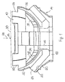
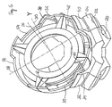
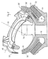
- 10 denotes a platform.
- the Platform 10 is in a manner not shown by means of a Inner gimbal mounting around a central pivot point 12 pivoted on all sides.
- a stator 14 one Torque generator assembly is at pivot point 12 aligned.
- the stator 14 has a tubular Middle part 16 made of magnetizable material.
- To the tubular middle part 16 are at the platform 10 thereof four radial flange parts 18 are provided at the opposite end, each offset by 90 °.
- To the Flange parts 18 are substantially tangential to that Pivot point 12 extending magnet carrier 20 with plan bearing surfaces 22 formed.
- plate-shaped Permanent magnets 24 sit with their underside on the Magnetic carriers 20.
- the permanent magnets 24 are perpendicular to the Contact surface 22 of the magnet carrier 20 magnetized.
- the Permanent magnets 24 thus produce a pivot point 12 essentially radial magnetic field.
- pole pieces are provided on the stator 14 is that about the axis through the pivot point 12 of the Middle part 16 offset by 90 ° to each other are arranged.
- the pole pieces are angularly aligned with the Flange parts 18 and magnetic supports 20.
- the pole pieces each A pair form an air gap between them, the from spherical surfaces is limited.
- the spherical surfaces are curved around the pivot point 12.
- the outer pole pieces each pair are each on the top of one of the Permanent magnets 24 attached.
- the inner pole pieces are on the tubular middle part 16 on the platform 10 thereof molded end.
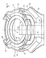
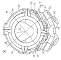
- a platform-fixed coordinate system with a Platform level vertical, in Fig. 3 vertical Z-axis 26 and the X- and. perpendicular to the Z-axis 26 and to each other Y axes 28 and 30 defined.
- the origin of the coordinates lies in the pivot point 12.
- Through the X axis 28 and Y-axis 30 in Figure 3 go vertical planes.
- One of these The vertical plane is the paper plane in Fig. 2.
- the other The vertical plane runs perpendicular to it through the Z axis 26.
- the flange parts, magnetic carriers, permanent magnets and pole pieces are arranged symmetrically to these vertical planes.
- Fig.1 and 2 are two diametrically opposite one another Pairs of pole pieces 32 and 34 or 36 and 38 can be seen.
- In 3 shows the pair of pole pieces 32 in the foreground and 34 and a pair of Pole shoes 40 and 42. In the background are the ends of the in addition diametrically opposite pole shoes 36 and 38 or 44 and 46 recognizable.
- the pole pieces 32, 36, 40 and 44 are "outer" pole pieces, i.e. are further from Pivot point 12 removed as the "inner” pole pieces 34, 38, 42 and 46.
- an air gap 48 is formed between the outer and inner pole pieces, e.g. 32 and 34.
- the Air gap 48 is from spherical to pivot point 12 centered areas limited.
- a magnetic circle runs from one inner pole face of the permanent magnet 24 over the outer pole piece 32, the air gap 48, the inner pole piece 34 the tubular middle part 16, the Flange part 18 and the magnet carrier 20 to the other, outer pole surface of the permanent magnet 24. This is in the Air gap creates an essentially radial magnetic field. The magnetic lines of force are distributed evenly over the area of the air gap. In the other pairs of pole pieces are correspondingly educated.
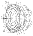
- the coil 50 has an arcuate inner section 58 and an equally arcuate outer portion 60.
- Inner portion 58 and outer portion 60 are short End portions 62 and 64 connected together.
- the wires run in the inner portion 58 and the outer portion 60 in the circumferential direction of the platform 10.
- the end portions 62 and 64 run radially. It so turns are formed that are essentially parallel to the plane of the platform 10 or to a perpendicular to the Paper level in Fig.2 running plane.
- the Outer section 60 is spherical about the pivot point 12 curved surfaces 66 and 68 limited. As from Fig.2 and 3 best seen are the wires of the turns in the inner section 58 of each coil in several layers wrapped on top of each other to form a compact bundle. In the end sections 62 and 64 the wires fanned.
- the outer sections 60 are flat with one or a few layers of turns comparatively large axial extent, so that the Outer portions 60 into a fairly narrow air gap 48 can intervene.
- the coils 50, 52, 54 and 56 limit with theirs End sections to each other. Coils 50, 52, 54 and 56 grip one of the inner pole pieces 34, 42, 38 or 46.
- the respective outer parts 60 are in the air gaps 48 between the outer pole pieces and the inner pole pieces led, e.g. between the pole pieces 32 and 34 or 36 and 38 in Fig. 2.
- Diametrically opposed coils and magnetic Circles form one effective around an axis Torque motor.
- the coils 50 and 54 form together with the pole shoes 32 and 34 and pole shoes 36 and 38 magnetic circles running one around the X axis 28 acting torque generator. Act on the coils Forces whose direction is perpendicular to the radial direction of the magnetic field and perpendicular to that in Current flowing through the coils in the circumferential direction tangentially in going through the axis of the central part 16 Longitudinal planes., Approximately the paper plane in Fig. 2.
- the coils 52 and 56 with the via the pole shoes 40 and 42 or the pole shoes 44 and 46 magnetic circles running around the Y axis acting torque generator.
- the torque generators are driven by currents that are applied to the coils are.
- the torque generators grip over the coils directly on the platform 10, not on axes of the gimbal mounting of the platform.
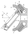
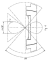
- the platform pivoted about the X axis to an angle of 40 ° become.
- the outer section 60 of the coil 54 remains within the air gap between the pole pieces 36 and 38. That through to the coil 54 at a given current the exerted torque of the coil 54 remains unaffected because the magnetic field in the entire air gap same thing.
- the coil 50 is in this position Platform completely moved out of the air gap 48 and makes no contribution to the torque.
- the Platform 10 from the position of Fig.1 also against Can be swiveled clockwise by 40 °.
- the X-axis 28 With such a pivoting of the platform 10 only by The X-axis 28 becomes the coils 52 seated on the X-axis and 56 compared to the associated pole pieces 40, 42 and 44, 46 twisted in the air gap. Since the coils, as shown in Fig.2 and 5 can be seen at a distance from that by the Pivot point 12 going X-axis are arranged to move they also translate relative to the Pole shoes as best seen in Fig. 6. Because of the spherical shape of Air gap and outer portion of the coil and the arcuate design of the coil is geometric possible.
- the platform can move around the Y axis be pivoted.
- the Platform 10 based on the position of Fig.1 to 3 also simultaneously around the X axis 28 and around the Y axis 30 be pivoted.
- a translational movement occurs of the axes opposite the stator 14. That is in the figures 10 through 12.
- 10 shows the stator 14 with the movements of the coordinate axes in side view seen in the direction of the Y axis of Fig. 3
- Fig.11 shows the Stator with the movements of the coordinate axes in Side view seen perpendicular to the Y axis.
- Fig. 12 is one perspective view with the movements of the Coordinate axes.
- Fig. 10 to 12 this is for the maximum swivel angle shown. 11 is that described by the X axis "8" curve labeled 72. As from Fig. 10 and 12 it can be seen that the "8" curves 72 are spherical Surfaces.
- the torque generator arrangement has a small one Size.
- the torque generator arrangement allows one large swivel range of the platform 10.
- the torques are essentially always in the axis system of the platform 10 generated.
- the inductance of the coils 50, 52, 54 and 56 is low, so that there is a high cut-off frequency.
- the Torque generator arrangement has no response threshold, no friction, no hysteresis, no reluctance moments, a small moving mass and a small electrical one Time constant. The torque generator arrangement works therefore, when targeting a viewfinder Missiles even with high roll rates and the occurrence of Squint angles perfectly.
Landscapes
- Physics & Mathematics (AREA)
- Engineering & Computer Science (AREA)
- General Physics & Mathematics (AREA)
- Radar, Positioning & Navigation (AREA)
- Remote Sensing (AREA)
- Reciprocating, Oscillating Or Vibrating Motors (AREA)
- Linear Motors (AREA)
Claims (4)
- Disposition de générateurs de couple de rotation présentant deux générateurs de couple de rotation fixes par rapport à la structure qui agissent sur deux axes perpendiculaires l'un à l'autre et qui mordent directement sur la plate-forme (10), et grâce auxquels des couples de rotation sont susceptibles d'être exercés sur une plate-forme (10), logée de façon susceptible de se déplacer de tous les côtés autour d'un point de pivotement central (12), autour de deux axes (28,30) perpendiculaires l'un à l'autre,(a) un stator (14) muni de quatre paires d'épanouissements polaires (32,34;36,38;40,42;44,46) étant prévu, épanouissements étant décalés les uns par rapport aux autres d'un angle de 90° autour d'un axe traversant le point de pivotement (12),(b) les épanouissements polaires (32,34;36,38;40,42;44,46) de chaque paire formant entre eux un entrefer (48) limité par des surfaces sphériques et les surfaces sphériques étant cintrées essentiellement autour du point de pivotement (12),(c) des aimants permanents (24) étant prévus, aimants formant un circuit magnétique avec les épanouissements polaires (32,34;36,38;40,42;44,46) et un blindage magnétique, un champ magnétique radial étant généré dans l'entrefer (48),(d) un induit muni de quatre bobines (50,52,54,56) cintrées, décalées les unes des autres de 90° et munies de spires s'étendant dans le sens circonférentiel étant relié à la plate-forme (10),
caractérisée par le fait que(e) les bobines (50,52,54,56) sont des bobines allongées, et(f) chacune de ces bobines (50,52,54,56) mord avec une section de bobine (60) cintrée dans l'entrefer (48) de chaque fois l'une des paires d'épanouissements polaires (32,34;36,38;40,42;44,46). - Disposition de générateurs de couple de rotation selon la revendication 1, caractérisée par le fait que(a) chacune des bobines (50,52,54,56) présente une section intérieure cintrée (58), une section extérieure cintrée (60) et des sections terminales (62,65) essentiellement radiales, situées entre la section intérieure (58) et la section extérieure (60) et étant plus petites que les sections intérieures et extérieures (58,60), et(b) les sections extérieures (60) sont guidées dans les entrefers (48) entre les paires d'épanouissements polaires (32,34;36,38;40,42;44,46).
- Disposition de générateurs de couple de rotation selon la revendication 2, caractérisée par le fait que la section extérieure (60) des bobines (50,52,54,56) est délimitée par des surfaces sphériques.
- Disposition de générateurs de couple de rotation selon la revendication 3, caractérisée par le fait que(a) des éléments de bride radiaux (18) sont formés à l'extrémité opposée à la plate-forme (10) d'un élément médian tubulaire (16) composé d'un matériau magnétisable et des supports d'aimant (20) munis de surfaces d'appui planes et s'étirant essentiellement dans la tangente du point de pivotement (12) sont formés sur les éléments de bride (18),(b) des aimants permanents (24) en forme de plaque reposent, avec leur face inférieure, sur les supports d'aimant (20) et sont magnétisés perpendiculairement par rapport à la surface d'appui des supports d'aimant (20),(c) les épanouissements polaires extérieurs (32,40,36,44) de chaque paire sont à chaque fois fixés sur la face supérieure de l'un des aimants permanents (24), et(d) les épanouissements polaires intérieurs (34,42,38,46) sont formés sur l'élément médian tubulaire (16).
Applications Claiming Priority (2)
| Application Number | Priority Date | Filing Date | Title |
|---|---|---|---|
| DE19535905 | 1995-09-27 | ||
| DE19535905A DE19535905A1 (de) | 1995-09-27 | 1995-09-27 | Drehmomenterzeuger-Anordnung |
Publications (3)
| Publication Number | Publication Date |
|---|---|
| EP0766065A2 EP0766065A2 (fr) | 1997-04-02 |
| EP0766065A3 EP0766065A3 (fr) | 1998-07-01 |
| EP0766065B1 true EP0766065B1 (fr) | 2002-04-24 |
Family
ID=7773302
Family Applications (1)
| Application Number | Title | Priority Date | Filing Date |
|---|---|---|---|
| EP96114201A Expired - Lifetime EP0766065B1 (fr) | 1995-09-27 | 1996-09-05 | Arrangement générateur de couple |
Country Status (3)
| Country | Link |
|---|---|
| US (1) | US5892310A (fr) |
| EP (1) | EP0766065B1 (fr) |
| DE (2) | DE19535905A1 (fr) |
Cited By (1)
| Publication number | Priority date | Publication date | Assignee | Title |
|---|---|---|---|---|
| WO2004088237A1 (fr) | 2003-03-29 | 2004-10-14 | Diehl Bgt Defence Gmbh & Co. Kg | Autodirecteur dote d'un systeme de cardans interne de tangage et de lacet |
Families Citing this family (6)
| Publication number | Priority date | Publication date | Assignee | Title |
|---|---|---|---|---|
| FR2797478B1 (fr) * | 1999-08-09 | 2001-10-12 | Cit Alcatel | Palier magnetique de centrage a commande en basculement de grande amplitude |
| FR2797477B1 (fr) * | 1999-08-09 | 2001-10-12 | Cit Alcatel | Palier magnetique du type rotule pour corps basculant |
| US6326714B1 (en) * | 1999-10-27 | 2001-12-04 | Moog Inc. | Two-axis pointing motor |
| DE10304905B3 (de) * | 2003-02-06 | 2004-05-13 | Siemens Ag | Abdeckung für ein elektronisches Gerät |
| DE102005028248C5 (de) | 2005-06-17 | 2018-06-07 | Diehl Defence Gmbh & Co. Kg | Elektromechanische Einrichtung mit einem um mindestens eine erste und eine zweite Drehachse drehbaren Element |
| US9774228B2 (en) * | 2015-02-12 | 2017-09-26 | Franke & Heydrich Kg | Drive system in the form of a torque motor |
Family Cites Families (13)
| Publication number | Priority date | Publication date | Assignee | Title |
|---|---|---|---|---|
| US3530318A (en) * | 1968-04-15 | 1970-09-22 | Mesur Matic Electronics Corp | Wobble coil stepping motor |
| US3559936A (en) * | 1968-11-26 | 1971-02-02 | Singer General Precision | Motion simulator |
| US3585425A (en) * | 1969-09-25 | 1971-06-15 | Mesur Matic Electronics Corp | Moving coil step motor |
| US3609422A (en) * | 1969-12-17 | 1971-09-28 | Teletype Corp | Wobble element motor |
| US4056760A (en) * | 1973-02-19 | 1977-11-01 | Ernst Leitz G.M.B.H. | Method of driving a two coordinate oscillator and circuit arrangement therefor |
| DE3378425D1 (en) * | 1983-06-16 | 1988-12-15 | Hughes Aircraft Co | Seeker gyroscope having reduced cross-coupling between rotor spin and precession |
| US4785212A (en) * | 1986-04-21 | 1988-11-15 | The Charles Stark Draper Laboratory, Inc. | Large angle magnetic suspension system |
| US4828376A (en) * | 1987-02-17 | 1989-05-09 | Martin Marietta Corporation | Triaxis stabilized platform |
| US4874998A (en) * | 1987-06-11 | 1989-10-17 | International Business Machines Corporation | Magnetically levitated fine motion robot wrist with programmable compliance |
| DE4005274A1 (de) * | 1990-02-20 | 1991-08-22 | Bodenseewerk Geraetetech | Dynamisch abgestimmter kreisel |
| US5252870A (en) * | 1991-03-01 | 1993-10-12 | Jacobsen Stephen C | Magnetic eccentric motion motor |
| US5204573A (en) * | 1991-07-17 | 1993-04-20 | Vision Applications, Inc. | Two-dimensional pointing motor |
| US5142932A (en) * | 1991-09-04 | 1992-09-01 | The United States Of America As Represented By The Administrator Of The National Aeronautics And Space Administration | Flexible robotic arm |
-
1995
- 1995-09-27 DE DE19535905A patent/DE19535905A1/de not_active Withdrawn
-
1996
- 1996-09-05 DE DE59609120T patent/DE59609120D1/de not_active Expired - Lifetime
- 1996-09-05 EP EP96114201A patent/EP0766065B1/fr not_active Expired - Lifetime
- 1996-09-27 US US08/722,290 patent/US5892310A/en not_active Expired - Lifetime
Cited By (2)
| Publication number | Priority date | Publication date | Assignee | Title |
|---|---|---|---|---|
| WO2004088237A1 (fr) | 2003-03-29 | 2004-10-14 | Diehl Bgt Defence Gmbh & Co. Kg | Autodirecteur dote d'un systeme de cardans interne de tangage et de lacet |
| DE10313136B4 (de) * | 2003-03-29 | 2017-05-11 | Diehl Defence Gmbh & Co. Kg | Suchkopf mit Nick-Gier-Innenkardansystem |
Also Published As
| Publication number | Publication date |
|---|---|
| EP0766065A2 (fr) | 1997-04-02 |
| DE59609120D1 (de) | 2002-05-29 |
| DE19535905A1 (de) | 1997-04-03 |
| US5892310A (en) | 1999-04-06 |
| EP0766065A3 (fr) | 1998-07-01 |
Similar Documents
| Publication | Publication Date | Title |
|---|---|---|
| DE69120530T2 (de) | Elektromagnetischer betätiger | |
| EP2992378B1 (fr) | Dispositif scanner | |
| EP0127741B1 (fr) | Système de suspension pour un véhicule automobile | |
| EP0523002A1 (fr) | Aimant composé comprenant plusieurs aimants individuels et palier magnétique permanent avec un aimant composé comprenant plusieurs aimants individuels | |
| DE10052912A1 (de) | Zweiachsiger Stellmotor | |
| DE3640188C2 (de) | Stellglied | |
| DE2751040C2 (de) | Kreiselgerät | |
| EP0920605B1 (fr) | Detecteur de position magnetique | |
| DE102014005247A1 (de) | Sensorvorrichtung | |
| EP0938035A2 (fr) | Dispositif électromécanique de contrÔle | |
| DE69121595T2 (de) | Drehendes elektromagnetisches einphasenbetätigungsorgan | |
| DE19535886B4 (de) | Suchkopf für Flugkörper | |
| DE8523360U1 (de) | Synchronmotor | |
| DE19535905A1 (de) | Drehmomenterzeuger-Anordnung | |
| WO1999005475A1 (fr) | Capteur de position magnetique | |
| EP0444445A1 (fr) | Gyroscope réglé dynamiquement | |
| EP0186749A1 (fr) | Résistance ajustable | |
| DE19731555A1 (de) | Magnetischer Positionssensor | |
| DE3431523A1 (de) | Steuersignalgeber | |
| AT383874B (de) | Reibungsfreies permanentmagnetisches lager | |
| DE19823725B4 (de) | Optische Ablenkvorrichtung | |
| EP0475543B1 (fr) | Palier à pendule pour une pendule de mesure à précision | |
| EP4211707A2 (fr) | Dispositif de réglage, système de réglage et produit-programme d'ordinateur | |
| DE3005921A1 (de) | Monostabiles drehankersystem | |
| DE102017211119A1 (de) | Maschine mit frei rotierbarem Rotor und Positionierungsvorrichtung |
Legal Events
| Date | Code | Title | Description |
|---|---|---|---|
| PUAI | Public reference made under article 153(3) epc to a published international application that has entered the european phase |
Free format text: ORIGINAL CODE: 0009012 |
|
| AK | Designated contracting states |
Kind code of ref document: A2 Designated state(s): DE FR GB IT |
|
| PUAL | Search report despatched |
Free format text: ORIGINAL CODE: 0009013 |
|
| AK | Designated contracting states |
Kind code of ref document: A3 Designated state(s): DE FR GB IT |
|
| 17P | Request for examination filed |
Effective date: 19980606 |
|
| 17Q | First examination report despatched |
Effective date: 20001215 |
|
| GRAG | Despatch of communication of intention to grant |
Free format text: ORIGINAL CODE: EPIDOS AGRA |
|
| GRAG | Despatch of communication of intention to grant |
Free format text: ORIGINAL CODE: EPIDOS AGRA |
|
| GRAH | Despatch of communication of intention to grant a patent |
Free format text: ORIGINAL CODE: EPIDOS IGRA |
|
| REG | Reference to a national code |
Ref country code: GB Ref legal event code: IF02 |
|
| GRAH | Despatch of communication of intention to grant a patent |
Free format text: ORIGINAL CODE: EPIDOS IGRA |
|
| GRAA | (expected) grant |
Free format text: ORIGINAL CODE: 0009210 |
|
| AK | Designated contracting states |
Kind code of ref document: B1 Designated state(s): DE FR GB IT |
|
| REG | Reference to a national code |
Ref country code: GB Ref legal event code: FG4D Free format text: NOT ENGLISH |
|
| REF | Corresponds to: |
Ref document number: 59609120 Country of ref document: DE Date of ref document: 20020529 |
|
| GBT | Gb: translation of ep patent filed (gb section 77(6)(a)/1977) |
Effective date: 20020710 |
|
| ET | Fr: translation filed | ||
| PLBE | No opposition filed within time limit |
Free format text: ORIGINAL CODE: 0009261 |
|
| STAA | Information on the status of an ep patent application or granted ep patent |
Free format text: STATUS: NO OPPOSITION FILED WITHIN TIME LIMIT |
|
| 26N | No opposition filed |
Effective date: 20030127 |
|
| PGFP | Annual fee paid to national office [announced via postgrant information from national office to epo] |
Ref country code: GB Payment date: 20120920 Year of fee payment: 17 |
|
| PGFP | Annual fee paid to national office [announced via postgrant information from national office to epo] |
Ref country code: DE Payment date: 20121121 Year of fee payment: 17 Ref country code: FR Payment date: 20121010 Year of fee payment: 17 |
|
| PGFP | Annual fee paid to national office [announced via postgrant information from national office to epo] |
Ref country code: IT Payment date: 20120926 Year of fee payment: 17 |
|
| GBPC | Gb: european patent ceased through non-payment of renewal fee |
Effective date: 20130905 |
|
| REG | Reference to a national code |
Ref country code: FR Ref legal event code: ST Effective date: 20140530 |
|
| REG | Reference to a national code |
Ref country code: DE Ref legal event code: R119 Ref document number: 59609120 Country of ref document: DE Effective date: 20140401 |
|
| PG25 | Lapsed in a contracting state [announced via postgrant information from national office to epo] |
Ref country code: GB Free format text: LAPSE BECAUSE OF NON-PAYMENT OF DUE FEES Effective date: 20130905 |
|
| PG25 | Lapsed in a contracting state [announced via postgrant information from national office to epo] |
Ref country code: DE Free format text: LAPSE BECAUSE OF NON-PAYMENT OF DUE FEES Effective date: 20140401 Ref country code: IT Free format text: LAPSE BECAUSE OF NON-PAYMENT OF DUE FEES Effective date: 20130905 Ref country code: FR Free format text: LAPSE BECAUSE OF NON-PAYMENT OF DUE FEES Effective date: 20130930 |