EP0766068A2 - Dispositif optique pour la mesure de grandeurs physiques - Google Patents
Dispositif optique pour la mesure de grandeurs physiques Download PDFInfo
- Publication number
- EP0766068A2 EP0766068A2 EP96106812A EP96106812A EP0766068A2 EP 0766068 A2 EP0766068 A2 EP 0766068A2 EP 96106812 A EP96106812 A EP 96106812A EP 96106812 A EP96106812 A EP 96106812A EP 0766068 A2 EP0766068 A2 EP 0766068A2
- Authority
- EP
- European Patent Office
- Prior art keywords
- grating
- measuring
- radiation
- correction
- diffracted
- Prior art date
- Legal status (The legal status is an assumption and is not a legal conclusion. Google has not performed a legal analysis and makes no representation as to the accuracy of the status listed.)
- Withdrawn
Links
- 230000003287 optical effect Effects 0.000 title claims abstract description 17
- 230000005855 radiation Effects 0.000 claims abstract description 42
- 238000005259 measurement Methods 0.000 claims description 8
- 238000011156 evaluation Methods 0.000 claims description 7
- 238000010276 construction Methods 0.000 description 3
- 238000000034 method Methods 0.000 description 2
- 238000009826 distribution Methods 0.000 description 1
- 230000002123 temporal effect Effects 0.000 description 1
Images

Classifications
-
- G—PHYSICS
- G01—MEASURING; TESTING
- G01D—MEASURING NOT SPECIALLY ADAPTED FOR A SPECIFIC VARIABLE; ARRANGEMENTS FOR MEASURING TWO OR MORE VARIABLES NOT COVERED IN A SINGLE OTHER SUBCLASS; TARIFF METERING APPARATUS; MEASURING OR TESTING NOT OTHERWISE PROVIDED FOR
- G01D5/00—Mechanical means for transferring the output of a sensing member; Means for converting the output of a sensing member to another variable where the form or nature of the sensing member does not constrain the means for converting; Transducers not specially adapted for a specific variable
- G01D5/26—Mechanical means for transferring the output of a sensing member; Means for converting the output of a sensing member to another variable where the form or nature of the sensing member does not constrain the means for converting; Transducers not specially adapted for a specific variable characterised by optical transfer means, i.e. using infrared, visible, or ultraviolet light
- G01D5/32—Mechanical means for transferring the output of a sensing member; Means for converting the output of a sensing member to another variable where the form or nature of the sensing member does not constrain the means for converting; Transducers not specially adapted for a specific variable characterised by optical transfer means, i.e. using infrared, visible, or ultraviolet light with attenuation or whole or partial obturation of beams of light
- G01D5/34—Mechanical means for transferring the output of a sensing member; Means for converting the output of a sensing member to another variable where the form or nature of the sensing member does not constrain the means for converting; Transducers not specially adapted for a specific variable characterised by optical transfer means, i.e. using infrared, visible, or ultraviolet light with attenuation or whole or partial obturation of beams of light the beams of light being detected by photocells
- G01D5/36—Forming the light into pulses
- G01D5/38—Forming the light into pulses by diffraction gratings
Definitions
- the invention relates to an optical device for measuring physical quantities, in which at least a first grating structure and subsequently an at least partially measuring grating running along an annulus are arranged in an optical path for generating diffracted radiation, the diffracted radiation of which is detected by a sensor device and is provided a measurement result in the form of electrical signals is passed on to an evaluation arrangement.
- a device of this type is identified as known in DE 43 18 129 A1 as an exemplary embodiment.
- a measuring grating is arranged on a circular path, which performs a rotational movement in relation to a grating structure arranged in front of it in the optical path in the form of two reference grids. With both reference grids there are two diffracted on these incident measuring radiations in such a way that, with respect to certain diffraction orders, the measuring radiations of each reference grating meet and interfere on a point of impact on the measuring grating, the points of incidence on the measuring grating being diametrically opposed.
- the measuring grating is designed in such a way that the two measuring radiation impinging on the respective impact points are diffracted in a common direction, so that only one diffracted radiation emanates from each impact point of the measuring grating.
- the diffracted radiation is recorded with radiation sensors, the electrical output signals of which are processed in an evaluation arrangement in order to provide a measurement result.
- rotary movements can be resolved very high, ie in principle down to the nanometer range.
- changes in level of the interfered radiation which arise as a result of the relative movement between the reference grating and the measuring grating, or - when using a heterodyne-interferometric method - changes in phase relationships of the interfered radiation can be used. Changes in intensity are also measured in the evaluation of the phase relationships.
- the invention has for its object to develop an optical device of the type described above so that the physical quantities can be measured more accurately and reliably.
- the first grating structure is designed as at least one correction grating, with which a wavefront distorted by the geometry of the measuring grating is precorrected in such a way that the radiation diffracted by the measuring grating has a flat and parallel wavefront.
- An advantageous construction of the optical device consists in that the correction grating simultaneously serves as a reference grating with which an optical measuring radiation impinging on it is diffracted at an angle determined for the measuring grating. With this construction, additional reference grids are not necessary.
- the construction of the correction grating and of the measuring grating can largely be in the basic structure be the same, and the overall structure of the optical device and the adjustment are simplified.
- a rotary encoder for detecting a relative movement between two moving parts is advantageously constructed in such a way that the measuring grating is arranged on a rotating second part and that the correction grating is arranged on a stationary or concentric rotating first part.
- FIG. 1 shows an exemplary embodiment of an optical device for measuring physical quantities in the form of a rotary encoder. This device is used to measure a relative rotary movement between a first part 23 and a second part 27.
- Two correction gratings 22a and 22b are arranged on the part 23 as a grating structure, while a measuring grating 24 on a circular path is arranged on the second part 27, which is spaced apart in the beam path is arranged, the correction gratings 22b and 22a being arranged diametrically with respect to the axis of rotation of the measuring grid 24.
- 1, 1a and 1b, a first radiation 13 (cf. FIG.
- first and second measuring radiation 18, 19 are aligned as third and fourth measuring radiation, only the fourth measuring radiation 19a being shown.
- the parallel first and second measuring radiations 18, 19 impinge on the lower correction grating 22a in FIG. 1 and are diffracted by this onto an impact point 25 of the measuring grating 24, while the third and fourth measuring radiation 19a from the upper correction grating 22b in FIG. 1 second impact point 26 of the correction grid 24 are diffracted, the second impact point 26 being diametrically opposite the first impact point 25.
- the intensity changes at a specific location on the wavefront of the diffracted radiation 29 or 30 as a result of interference between the two respective measurement radiations.
- This change in intensity results in a different level of the output signals of the sensors 31 and 32, so that a rotary movement can be detected, the resolution being possible in principle down to the nanometer range, as is detailed in DE 43 18 129 A1.
- heterodyne interferometric methods which enables a measurement of phase relationships independent of random intensity fluctuations, the rotary movement can be measured even more reliably. This is also discussed in the publication mentioned.
- the grating structures are designed as correction grids with which distortions caused by the measuring grating 24 are precorrected, so that the interfered, diffracted radiations 29, 30 have a largely exact, parallel intensity profile in the Show wave fronts.
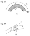
- FIG. 2A and 2B show how distortions of the wave fronts of the radiation diffracted by the measuring grating 24 arise.
- the track SP of the measuring grid 24 has a certain width. This results in different lattice constants depending on the radial distance from the center point over the track, the smallest lattice constant (eg line spacing) occurring on the inner circular path and the largest lattice constant d ′′ on the outer circular path. This results in distortions in the wavefront of the radiation 29 diffracted by the measuring grating 24, as is shown schematically in FIG. 2B for a phase profile of the radiation 29 diffracted at an angle ⁇ .
- Such phase progression is corrected in advance by means of the correction gratings 22a, 22b, ie the measurement radiation diffracted by the correction gratings 22a, 22b already contains a coordinated, compensating distortion of the wave fronts.
- the intensity profiles in the interference field can be precisely detected by means of the following radiation sensors 31 and 32 and can be precisely evaluated in the connected evaluation arrangement 35, without the need for a complex sensor device to take local distortions into account.
Landscapes
- Physics & Mathematics (AREA)
- General Physics & Mathematics (AREA)
- Length Measuring Devices By Optical Means (AREA)
- Photometry And Measurement Of Optical Pulse Characteristics (AREA)
- Optical Transform (AREA)
Applications Claiming Priority (2)
| Application Number | Priority Date | Filing Date | Title |
|---|---|---|---|
| DE1995136141 DE19536141A1 (de) | 1995-09-28 | 1995-09-28 | Optische Vorrichtung zum Messen physikalischer Größen |
| DE19536141 | 1995-09-28 |
Publications (2)
| Publication Number | Publication Date |
|---|---|
| EP0766068A2 true EP0766068A2 (fr) | 1997-04-02 |
| EP0766068A3 EP0766068A3 (fr) | 1998-11-18 |
Family
ID=7773458
Family Applications (1)
| Application Number | Title | Priority Date | Filing Date |
|---|---|---|---|
| EP96106812A Withdrawn EP0766068A3 (fr) | 1995-09-28 | 1996-04-30 | Dispositif optique pour la mesure de grandeurs physiques |
Country Status (2)
| Country | Link |
|---|---|
| EP (1) | EP0766068A3 (fr) |
| DE (1) | DE19536141A1 (fr) |
Cited By (1)
| Publication number | Priority date | Publication date | Assignee | Title |
|---|---|---|---|---|
| WO2020228720A1 (fr) * | 2019-05-16 | 2020-11-19 | 清华大学 | Système d'étalonnage de réseau plan |
Family Cites Families (4)
| Publication number | Priority date | Publication date | Assignee | Title |
|---|---|---|---|---|
| DE4013566A1 (de) * | 1990-04-27 | 1991-11-07 | Heidenhain Gmbh Dr Johannes | Winkelmesseinrichtung |
| US5486923A (en) * | 1992-05-05 | 1996-01-23 | Microe | Apparatus for detecting relative movement wherein a detecting means is positioned in the region of natural interference |
| DE4318129A1 (de) * | 1993-06-01 | 1994-12-08 | Bosch Gmbh Robert | Vorrichtung zur Messung einer Bewegung zwischen zwei Teilen |
| US5442172A (en) * | 1994-05-27 | 1995-08-15 | International Business Machines Corporation | Wavefront reconstruction optics for use in a disk drive position measurement system |
-
1995
- 1995-09-28 DE DE1995136141 patent/DE19536141A1/de not_active Withdrawn
-
1996
- 1996-04-30 EP EP96106812A patent/EP0766068A3/fr not_active Withdrawn
Cited By (2)
| Publication number | Priority date | Publication date | Assignee | Title |
|---|---|---|---|---|
| WO2020228720A1 (fr) * | 2019-05-16 | 2020-11-19 | 清华大学 | Système d'étalonnage de réseau plan |
| US11940349B2 (en) | 2019-05-16 | 2024-03-26 | Tsinghua University | Plane grating calibration system |
Also Published As
| Publication number | Publication date |
|---|---|
| EP0766068A3 (fr) | 1998-11-18 |
| DE19536141A1 (de) | 1997-04-03 |
Similar Documents
| Publication | Publication Date | Title |
|---|---|---|
| EP0160811B1 (fr) | Dispositif de mesure photo-électrique | |
| DE2248194A1 (de) | Messgeraet | |
| EP3764064B1 (fr) | Dispositif optique de mesure de position | |
| DE4301971A1 (fr) | ||
| DE3905838A1 (de) | Optischer linearkodierer | |
| DE2501373B2 (de) | Anordnung zur Winkel- oder Längenmessung | |
| EP0141123A2 (fr) | Dispositif de mesure incrémental photoélectrique | |
| DE102007024593A1 (de) | Maßstab für eine Positionsmesseinrichtung und Positionsmesseinrichtung | |
| DE2063541C3 (de) | Elektrooptische Meßvorrichtung zur Vermessung des Trassenverlaufs und des Profilverlaufs einer Gleisstrecke | |
| DE102013217216A1 (de) | Verfahren und Vorrichtung zur Fehlerermittlung und Fehlerkompensation eines inkrementellen Sensors | |
| EP0766068A2 (fr) | Dispositif optique pour la mesure de grandeurs physiques | |
| DE2835390C2 (fr) | ||
| DE4423877A1 (de) | Längen- oder Winkelmeßeinrichtung | |
| DE102014215633A1 (de) | Positionsmesseinrichtung | |
| CH629297A5 (en) | Device for determining the polar coordinates of the offset of an object with respect to an optical reference line | |
| EP1674830A2 (fr) | Procédé destiné à l'amélioration de la qualité de signaux de voie sinusoïdaux | |
| DE4407446C1 (de) | Verfahren und Vorrichtung zur schnellen Interpolation von Zwischenwerten aus periodischen phasenverschobenen Signalen sowie deren Verwendung | |
| DE102004062278A1 (de) | Messelement und Messverfahren mit einer Spur zur Bestimmung einer Lage | |
| DE3322713A1 (de) | Verfahren und vorrichtung zur laufenden messung des rollwinkels eines beweglichen maschinenteiles | |
| CH638057A5 (en) | Electrooptic device for objective target acquisition | |
| EP0797108A1 (fr) | Procédé de mesure optique d'angles relatifs | |
| WO2022253388A1 (fr) | Procédé et dispositif de mesure d'un objet de mesure | |
| DE3813754A1 (de) | Vorrichtung zur erfassung der winkelposition eines drehbaren koerpers | |
| DE4105433C2 (de) | Einrichtung zur Konturformprüfung an einer Bearbeitungs- oder Meßmaschine | |
| DE19637625A1 (de) | Motor oder Generator mit zwei relativ zueinander beweglich gelagerten Teilen und einer Vorrichtung zum interferometrischen Messen eines Weges oder Drehwinkels |
Legal Events
| Date | Code | Title | Description |
|---|---|---|---|
| PUAI | Public reference made under article 153(3) epc to a published international application that has entered the european phase |
Free format text: ORIGINAL CODE: 0009012 |
|
| AK | Designated contracting states |
Kind code of ref document: A2 Designated state(s): DE FR GB IT |
|
| PUAL | Search report despatched |
Free format text: ORIGINAL CODE: 0009013 |
|
| AK | Designated contracting states |
Kind code of ref document: A3 Designated state(s): DE FR GB IT |
|
| STAA | Information on the status of an ep patent application or granted ep patent |
Free format text: STATUS: THE APPLICATION IS DEEMED TO BE WITHDRAWN |
|
| 18D | Application deemed to be withdrawn |
Effective date: 19990519 |