EP0766074A2 - Capteur de niveau de fluide - Google Patents
Capteur de niveau de fluide Download PDFInfo
- Publication number
- EP0766074A2 EP0766074A2 EP96306700A EP96306700A EP0766074A2 EP 0766074 A2 EP0766074 A2 EP 0766074A2 EP 96306700 A EP96306700 A EP 96306700A EP 96306700 A EP96306700 A EP 96306700A EP 0766074 A2 EP0766074 A2 EP 0766074A2
- Authority
- EP
- European Patent Office
- Prior art keywords
- path
- segments
- resistor element
- contact
- sensor
- Prior art date
- Legal status (The legal status is an assumption and is not a legal conclusion. Google has not performed a legal analysis and makes no representation as to the accuracy of the status listed.)
- Withdrawn
Links
Images


Classifications
-
- H—ELECTRICITY
- H01—ELECTRIC ELEMENTS
- H01C—RESISTORS
- H01C10/00—Adjustable resistors
- H01C10/30—Adjustable resistors the contact sliding along resistive element
- H01C10/305—Adjustable resistors the contact sliding along resistive element consisting of a thick film
-
- G—PHYSICS
- G01—MEASURING; TESTING
- G01F—MEASURING VOLUME, VOLUME FLOW, MASS FLOW OR LIQUID LEVEL; METERING BY VOLUME
- G01F23/00—Indicating or measuring liquid level or level of fluent solid material, e.g. indicating in terms of volume or indicating by means of an alarm
- G01F23/30—Indicating or measuring liquid level or level of fluent solid material, e.g. indicating in terms of volume or indicating by means of an alarm by floats
- G01F23/32—Indicating or measuring liquid level or level of fluent solid material, e.g. indicating in terms of volume or indicating by means of an alarm by floats using rotatable arms or other pivotable transmission elements
- G01F23/36—Indicating or measuring liquid level or level of fluent solid material, e.g. indicating in terms of volume or indicating by means of an alarm by floats using rotatable arms or other pivotable transmission elements using electrically actuated indicating means
-
- G—PHYSICS
- G01—MEASURING; TESTING
- G01F—MEASURING VOLUME, VOLUME FLOW, MASS FLOW OR LIQUID LEVEL; METERING BY VOLUME
- G01F23/00—Indicating or measuring liquid level or level of fluent solid material, e.g. indicating in terms of volume or indicating by means of an alarm
- G01F23/30—Indicating or measuring liquid level or level of fluent solid material, e.g. indicating in terms of volume or indicating by means of an alarm by floats
- G01F23/64—Indicating or measuring liquid level or level of fluent solid material, e.g. indicating in terms of volume or indicating by means of an alarm by floats of the free float type without mechanical transmission elements
- G01F23/68—Indicating or measuring liquid level or level of fluent solid material, e.g. indicating in terms of volume or indicating by means of an alarm by floats of the free float type without mechanical transmission elements using electrically actuated indicating means
Definitions
- the present invention relates to fluid level sensors.
- a conventional fuel level sensor In sensing the level of fuel in the fuel tank of a motor vehicle, a conventional fuel level sensor has a resistor card.
- the conventional fuel level sensor also has a float which follows the level of fuel in the fuel tank. Responsive to the movement of the float is a contact which follows a path on the resistor card. Through this movement of the contact in response to the fuel level in the tank, a variable resistance is provided by the fuel level sensor.
- a fuel gauge electrically coupled to the fuel level sensor measures the variable resistance and displays the level of fuel in the fuel tank.
- the path followed by the contact is along metallized conductors running transverse to the path followed by the-contact.
- the conductors are all in electrical contact with resistive ink applied to the resistor card.
- resistive ink applied to the resistor card.
- the overprinted resistive material is less "friendly" of a material on which to travel for the contact of the fuel level sensor.
- One manifestation of this situation is that the relatively coarse resistive material provides a somewhat electrically “noisy” signal. In some fuel gauges, this noisy signal can provide a concern regarding proper operation of the gauge.
- the present invention provides a sensor for measuring a level of liquid in a vessel.
- the sensor comprises a resistor element having an insulating substrate and a float adapted to move in response to the liquid level.
- the sensor includes a contact responsively coupled to the float and disposed to travel in a path on the resistor element, the travel responsive to the movement of the float in response to the liquid level.
- the sensor comprises a resistive layer deposited on the insulating substrate, at least a portion of the resistive layer located along the path followed by the contact.
- the sensor includes conductive segments deposited on the resistive layer along the path, the conductive segments disposed such that travel of the contact along its path will result in the contact successively contacting the segments.
- the present invention also provides a resistor element for a fluid level sensor.
- the resistor element comprises an insulating substrate and a path adapted for travel by an electrical contact in response to the fluid level. Further, the resistor element includes a resistive layer deposited on the insulating substrate, at least a portion of the resistive layer located along the path. Also, the resistor element comprises conductive segments disposed on the resistive layer along the path, the conductive segments disposed such that travel of the contact along the path will result in the contact successively contacting the conductive segments.
- the present invention provides a highly-durable fluid level sensor having low electrical noise. These advantages are provided without needing three printed layers of conductive and/or resistive material in the sensor.
- Fuel level sensor 20 includes a resistor element 22 and a float 24. Fuel level sensor 20 is preferably suspended vertically in a fuel tank of a motor vehicle. Float 24 moves up and down with the level of fuel in the fuel tank.
- Resistor element 22 has a substrate 23 preferably comprising metal coated with electrically-insulating ceramic material. Disposed on the substrate 23 of resistor element 22 are two tracks 26 and 28. Track 26 is made of high-conductivity material and is connected to solder pad 30. Track 28 is connected via fixed resistor 32 and conductor 34 to solder pad 36. Track 28 is designed to be electrically resistive. The construction of track 28 will be described in more detail below.
- Wires 38 and 40 are soldered to solder pads 30 and 36 for connection of fuel level sensor 20 to an analog or digital fuel gauge (not shown).
- an edge-board-type connector having spring-loaded terminals crimped and/or soldered to wires 38 and 40 can be employed. With the edge-board connector in place on resistor element 22, the terminals would be biased against pads 30 and 36.
- float 24 includes a contact member 42 having contacts 44 and 46 which are electrically coupled to one another and are further biased against resistor element 22.
- Contact 44 rides in contact with track 26 as float 24 moves up and down.
- contact 46 rides in contact with track 28 as float 24 moves up and down.
- a variable resistance is coupled between solder pads 30 and 36.
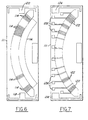
- resistor element 22 The construction of resistor element 22 will be described with reference to Figure 3.
- Resistor material 48 is applied to the insulating substrate of resistor element 22.
- the resistor material 48 includes a first portion 50 along the path followed by contact 46 of float 24 (Fig. 2). This first portion 50 is divided into discrete segments 52.
- Resistor material 48 further comprises a trim section 54. This trim section 54 is joined to segments 52 of first portion 50.
- Resistor material 48 also comprises fixed resistor 32.
- Resistor material 48 can be a number of materials, among them palladium-type or ruthenium-type resistive ink.
- the ink is preferably applied by a silk-screen thick-film process.
- conductor material 49 is applied in the locations shown in Figure 4. Note that the resistor material 48 described with reference to Figure 3 is not shown in Figure 4 for clarity of presentation.
- the conductor material 49 includes track 26, conductor 34 and solder pads 30 and 36, as previously described with reference to Figure 1.
- the conductor material 49 also includes a series of discrete pads 58.
- Pads 58 are electrically isolated from one another (but for the fact that they are in electrical communication with one another through resistor material 48 (Fig. 3).
- Pads 58 are located coincidentally on top of segments 52 of resistor material 48.
- Pads 58 are spaced such that contact 46 (Fig. 2) is always in contact with at least one pad 58, unless perhaps when float 24 is at the extreme top or bottom of its travel. That is, contact 46 will experience no discontinuities between pads 58.
- the conductor material 49 can be a number of high-conductivity materials including high-silver-content silver-palladium ink.
- the ink is preferably applied by a silk-screen thick-film process.
- both resistive segments 52 and conductive pads 58 are angled downward, in the direction that float 24 (Fig. 1) travels as the fuel level in the fuel tank is decreasing. This downward angling helps assure that contact 46 of float 24 does not get "hung up” (that is, stuck) at the boundary between two pads 58. This concern about contact 46 getting "hung up” is really only a potential concern when fuel level is decreasing. When fuel level is increasing (that is, when the fuel tank is being filled), float 24 has sufficient buoyancy to be reliably raised by the increasing fuel level.
- the high reliability with which float 24 will move downward in the present design means that float 24 can be made less massive (and therefore smaller) than would otherwise be required.
- the reduced size of float 24 means that float 24 can move closer to the bottom and top of resistive element 22 in sensing fuel level. This provides increased flexibility in designing a fuel tank/fuel level sensor system.
- variable resistance will be provided between solder pads 30 and 36. This variable resistance is indicative of the fuel level in the fuel tank.
- fixed resistor 32 is coupled between solder pads 30 and 36.
- trim section 54 of the resistor material 48 of fuel level sensor 20 can be trimmed to assure that the resistance provided by fuel level sensor 20 at test points 64 is precisely to specification.
- the trimming can include straight trims 60, "L"-shaped trims 62 or abrasions in the trim section 54 to modify the resistance of fuel level sensor 20.
- fuel level sensor 20 reduces electrical noise which can otherwise be generated by contact 46 riding on relatively coarse resistive material. As was illustrated with reference to Figures 3 and 4, only two printing steps (versus three in alternative designs) are used.
- Resistive element 110 is designed for use in conventional fuel level sensors having a float attached to an arm. The float moves up and down with fuel level, moving a contact along a path 112. Resistive element 110 comprises a resistive layer and a conductive layer applied to an insulating substrate 111.
- Figure 6 shows a resistive layer applied to substrate 111.
- This resistive layer includes resistor material disposed in segments 114 disposed along path 112 (Fig. 5). These segments 114 are spaced apart by a small spacing. Segments 114 all contact a trim section 116. Fixed resistors 118 and 120, formed of resistor material, are also provided.
- Figure 7 shows a conductive layer which is added after the resistive layer. Note that the resistive layer of Figure 6 is omitted in Figure 7 for clarity of presentation.
- the conductive layer includes discrete pads 122, which are disposed coincidentally on segments 114 of resistor material.
- the conductive layer further includes solder pads 124 and 126. Additionally, the conductive layer includes test pads 128, for testing the resistance of the fuel level sensor containing resistive element 110.
- a wire (not shown) is soldered to solder pad 124 or 126, depending upon which end of resistor element 112 is approached by the contact as the fuel level in the fuel tank decreases.
- a second wire is customarily coupled to the contact which moves along path 112 as the fuel level in the fuel tank changes. A variable resistance between those two wires is thus provided. This resistance is a function of the fuel level in the fuel tank and can be measured by a fuel gauge.
- fixed resistor 118 or 120 provides a fixed resistance value when the fuel level in the fuel tank is empty.
- Trim section 116 can be trimmed as necessary such that the resistance of resistive element 110 is within specification at all test points 128. This trimming can be done in any of the variations discussed in relation to Figure 1.
Landscapes
- Physics & Mathematics (AREA)
- Fluid Mechanics (AREA)
- General Physics & Mathematics (AREA)
- Engineering & Computer Science (AREA)
- Microelectronics & Electronic Packaging (AREA)
- Level Indicators Using A Float (AREA)
Applications Claiming Priority (2)
| Application Number | Priority Date | Filing Date | Title |
|---|---|---|---|
| US534780 | 1990-06-07 | ||
| US08/534,780 US5743136A (en) | 1995-09-27 | 1995-09-27 | Fluid level sensor with resistive and conductive layers |
Publications (2)
| Publication Number | Publication Date |
|---|---|
| EP0766074A2 true EP0766074A2 (fr) | 1997-04-02 |
| EP0766074A3 EP0766074A3 (fr) | 1997-07-16 |
Family
ID=24131510
Family Applications (1)
| Application Number | Title | Priority Date | Filing Date |
|---|---|---|---|
| EP96306700A Withdrawn EP0766074A3 (fr) | 1995-09-27 | 1996-09-16 | Capteur de niveau de fluide |
Country Status (2)
| Country | Link |
|---|---|
| US (1) | US5743136A (fr) |
| EP (1) | EP0766074A3 (fr) |
Cited By (4)
| Publication number | Priority date | Publication date | Assignee | Title |
|---|---|---|---|---|
| EP0989390A1 (fr) * | 1998-09-23 | 2000-03-29 | Pierburg Aktiengesellschaft | Indicateur électrique de niveau pour réservoirs de carburant d'un véhicule |
| EP1271567A3 (fr) * | 2001-06-28 | 2003-11-19 | Yazaki Corporation | Procédé de varier la valeur de résistance |
| EP1327124A4 (fr) * | 2000-10-06 | 2006-01-04 | Delphi Tech Inc | Ensemble carte de resistance en ceramique pour capteur de carburant |
| EP3821213B1 (fr) * | 2018-07-10 | 2022-09-07 | Vitesco Technologies GmbH | Générateur de signal pour un capteur de niveau d'un récipient d'un véhicule automobile et procédé de production d'un tel générateur de signal |
Families Citing this family (23)
| Publication number | Priority date | Publication date | Assignee | Title |
|---|---|---|---|---|
| WO2000060321A1 (fr) | 1999-04-01 | 2000-10-12 | Rochester Gauges, Inc. | Dispositif transmetteur de niveau de liquide |
| DE10028893A1 (de) * | 1999-06-30 | 2001-06-21 | Alfmeier Praez Ag | Füllstandsgeber für den Kraftstofftank eines Kraftfahrzeuges |
| US6634229B1 (en) * | 1999-11-16 | 2003-10-21 | Illinois Tool Works Inc. | Resistive fluid level sensing and control system |
| US6367325B1 (en) | 2000-01-13 | 2002-04-09 | Visteon Global Technologies, Inc. | Motor vehicle fuel level sensor |
| US6588288B1 (en) | 2000-09-19 | 2003-07-08 | Rochester Gauges, Inc. | Resistive element structure for a sender assembly of a gauge |
| US6564631B1 (en) | 2002-04-19 | 2003-05-20 | Delphi Technologies, Inc. | Digital signal fuel sensor |
| US6886403B2 (en) * | 2003-06-17 | 2005-05-03 | Delphi Technologies, Inc. | Sensor with amorphous electrode |
| US6862919B2 (en) * | 2003-06-17 | 2005-03-08 | Delphi Technologies, Inc. | Ethanol and volatility sensor and fabrication method |
| WO2005047827A2 (fr) * | 2003-11-12 | 2005-05-26 | Stemco Llc | Capteur conducteur pour la detection de niveau de fluide |
| US7921873B2 (en) | 2004-01-22 | 2011-04-12 | Rochester Gauges, Inc. | Service valve assembly having a stop-fill device and a liquid level indicating dial |
| US7293578B2 (en) | 2004-01-22 | 2007-11-13 | Rochester Gauges, Inc. | Gauge assembly having a stop fill device |
| US7726334B2 (en) | 2004-01-22 | 2010-06-01 | Rochester Gauges, Inc. | Service valve assembly having a stop-fill device and remote liquid level indicator |
| US7091819B1 (en) | 2005-06-22 | 2006-08-15 | Ti Group Automotive Systems, L.L.C. | Variable resistor card for a fuel level sensor |
| US7392700B2 (en) * | 2005-07-15 | 2008-07-01 | Chrysler Llc | Method and system for determining fuel level |
| USD583693S1 (en) | 2006-03-30 | 2008-12-30 | Rochester Gauges, Inc. | Dial assembly for a gauge |
| US20100229964A1 (en) * | 2006-08-18 | 2010-09-16 | Rochester Gauges, Inc. | Service valve assembly having a stop-fill device and remote liquid level indicator |
| US20080282818A1 (en) * | 2007-05-17 | 2008-11-20 | Charles Smith | Sensors with nanoparticles |
| US7690323B2 (en) * | 2007-10-31 | 2010-04-06 | Rochester Gauges, Inc. | Gauge head assembly with non-magnetic insert |
| CA2753588C (fr) * | 2011-09-27 | 2016-01-26 | Westport Power Inc. | Appareil et methode d'estimation du volume et de la masse d'un fluide polyphase conserve a des temperatures cryogeniques |
| US12422391B2 (en) | 2019-08-27 | 2025-09-23 | Chemelex Europe Gmbh | Ruggedized sensor for detecting organic liquids |
| USD953183S1 (en) | 2019-11-01 | 2022-05-31 | Nvent Services Gmbh | Fuel sensor |
| US11674840B2 (en) | 2021-09-20 | 2023-06-13 | Ford Global Technologies, Llc | Fluid-level sensor |
| US11709088B1 (en) * | 2022-04-29 | 2023-07-25 | Ford Global Technologies, Llc | Vehicle fluid-level sensor with articulating joint and sensor |
Family Cites Families (15)
| Publication number | Priority date | Publication date | Assignee | Title |
|---|---|---|---|---|
| JPS5496083A (en) * | 1978-01-14 | 1979-07-30 | Nissan Motor | Device for indicating distance which can be traveled with remaining fuel |
| DE3445541A1 (de) * | 1984-01-04 | 1985-07-11 | Skandiafabriken AB, Mullsjö | Fluessigkeits-fuellstandsanzeiger |
| JPH0241544Y2 (fr) * | 1985-08-13 | 1990-11-06 | ||
| DE3613521C1 (de) * | 1986-04-22 | 1986-11-06 | Daimler-Benz Ag, 7000 Stuttgart | Einrichtung zum elektrischen Messen des Niveaus einer in einem Kraftstofftank eines Fahrzeuges enthaltenen Fluessigkeit |
| IT1206845B (it) * | 1987-01-16 | 1989-05-11 | Fiat Auto Spa | Dispositivo per la misurazione del livello di carburante presente nel serbatoio di un autoveicolo e relativo procedimento di impiego |
| FR2613478B1 (fr) * | 1987-04-06 | 1992-04-10 | Jaeger | Dispositif de mesure comprenant un transducteur du type rheostat, en particulier pour la mesure de carburant dans le reservoir d'un vehicule automobile |
| US4827769A (en) * | 1988-09-16 | 1989-05-09 | Hamilton Standard Controls, Inc. | Fuel level sensor with buried conductor |
| US4931764A (en) * | 1988-12-27 | 1990-06-05 | Ford Motor Company | Low wear resistor card for use in a liquid fuel sender circuit |
| US4924704A (en) * | 1988-12-27 | 1990-05-15 | Ford Motor Company | Fuel sender assembly requiring no calibration and having reduced wear |
| US4873865A (en) * | 1988-12-27 | 1989-10-17 | Ford Motor Company | Fuel sender assembly requiring no calibration |
| US5051719A (en) * | 1990-06-11 | 1991-09-24 | Ford Motor Company | Thick-film non-step resistor with accurate resistance characteristic |
| US5146785A (en) * | 1991-01-30 | 1992-09-15 | Spectrol Electronics Corp. | Fluid level sensor with stair step output |
| US5129261A (en) * | 1991-02-20 | 1992-07-14 | Spectrol Electronics Corporation | Three wire potentiometric liquid level sensor |
| US5267475A (en) * | 1992-06-15 | 1993-12-07 | Ford Motor Company | Vertical sweep liquid level sensor |
| US5272918A (en) * | 1993-06-30 | 1993-12-28 | Ford Motor Company | Pivotal liquid level sensor assembly |
-
1995
- 1995-09-27 US US08/534,780 patent/US5743136A/en not_active Expired - Fee Related
-
1996
- 1996-09-16 EP EP96306700A patent/EP0766074A3/fr not_active Withdrawn
Cited By (7)
| Publication number | Priority date | Publication date | Assignee | Title |
|---|---|---|---|---|
| EP0989390A1 (fr) * | 1998-09-23 | 2000-03-29 | Pierburg Aktiengesellschaft | Indicateur électrique de niveau pour réservoirs de carburant d'un véhicule |
| EP1327124A4 (fr) * | 2000-10-06 | 2006-01-04 | Delphi Tech Inc | Ensemble carte de resistance en ceramique pour capteur de carburant |
| EP1271567A3 (fr) * | 2001-06-28 | 2003-11-19 | Yazaki Corporation | Procédé de varier la valeur de résistance |
| US6751848B2 (en) | 2001-06-28 | 2004-06-22 | Yazaki Corporation | Method for adjusting a resistance value of a film resistor |
| KR100464130B1 (ko) * | 2001-06-28 | 2005-01-03 | 야자키 소교 가부시키가이샤 | 저항치 조정방법 |
| EP3821213B1 (fr) * | 2018-07-10 | 2022-09-07 | Vitesco Technologies GmbH | Générateur de signal pour un capteur de niveau d'un récipient d'un véhicule automobile et procédé de production d'un tel générateur de signal |
| US11867551B2 (en) | 2018-07-10 | 2024-01-09 | Vitesco Technologies GmbH | Signal transmitter for a fill level sensor of a container of a motor vehicle, and method for producing a signal transmitter for a fill level sensor of a container of a motor vehicle |
Also Published As
| Publication number | Publication date |
|---|---|
| EP0766074A3 (fr) | 1997-07-16 |
| US5743136A (en) | 1998-04-28 |
Similar Documents
| Publication | Publication Date | Title |
|---|---|---|
| US5743136A (en) | Fluid level sensor with resistive and conductive layers | |
| US6021668A (en) | Indicator system | |
| US6212950B1 (en) | Glass interlaced fuel system low current rheostat | |
| US6985067B2 (en) | Fuel tank resistor card having improved corrosion resistance | |
| US4827769A (en) | Fuel level sensor with buried conductor | |
| US5051719A (en) | Thick-film non-step resistor with accurate resistance characteristic | |
| US4702107A (en) | Device for detecting the level of a liquid contained in a tank | |
| US6681628B2 (en) | Ceramic resistor card assembly for fuel sensor | |
| US5129261A (en) | Three wire potentiometric liquid level sensor | |
| EP0119673A1 (fr) | Transducteurs de force | |
| US4931764A (en) | Low wear resistor card for use in a liquid fuel sender circuit | |
| JP2002116078A (ja) | 抵抗式液位計測装置 | |
| WO2003023793A1 (fr) | Element resistif variable | |
| WO2000039536A2 (fr) | Detecteur de niveau de carburant a carte a resistance ceramique miniaturisee | |
| US6588288B1 (en) | Resistive element structure for a sender assembly of a gauge | |
| KR101252672B1 (ko) | 연료 레벨 센서 가변 레지스터 조립체 | |
| JPH07507866A (ja) | 鉛直方向掃引式液面センサ | |
| EP0493339A1 (fr) | Indicateur électrique de niveau de carburant pour réservoirs de véhicules à moteur et applications similaires | |
| WO2003003384A2 (fr) | Systeme de detection du niveau de combustible | |
| JPH0446180Y2 (fr) | ||
| WO2001054144A1 (fr) | Potentiometre | |
| JPS62288525A (ja) | タンク内の液面の検知装置 | |
| EP0419284A1 (fr) | Appareil détecteur de niveau de fluide | |
| JP2000193512A (ja) | 液面検出装置 | |
| US20110074448A1 (en) | Potentiometer |
Legal Events
| Date | Code | Title | Description |
|---|---|---|---|
| PUAI | Public reference made under article 153(3) epc to a published international application that has entered the european phase |
Free format text: ORIGINAL CODE: 0009012 |
|
| AK | Designated contracting states |
Kind code of ref document: A2 Designated state(s): DE FR GB |
|
| PUAL | Search report despatched |
Free format text: ORIGINAL CODE: 0009013 |
|
| AK | Designated contracting states |
Kind code of ref document: A3 Designated state(s): DE FR GB |
|
| 17P | Request for examination filed |
Effective date: 19971125 |
|
| 17Q | First examination report despatched |
Effective date: 19990315 |
|
| STAA | Information on the status of an ep patent application or granted ep patent |
Free format text: STATUS: THE APPLICATION IS DEEMED TO BE WITHDRAWN |
|
| 18D | Application deemed to be withdrawn |
Effective date: 20050401 |