EP0766082A1 - Methode und System zur Detektion von Schmutz an optischen Fasern - Google Patents
Methode und System zur Detektion von Schmutz an optischen Fasern Download PDFInfo
- Publication number
- EP0766082A1 EP0766082A1 EP96850153A EP96850153A EP0766082A1 EP 0766082 A1 EP0766082 A1 EP 0766082A1 EP 96850153 A EP96850153 A EP 96850153A EP 96850153 A EP96850153 A EP 96850153A EP 0766082 A1 EP0766082 A1 EP 0766082A1
- Authority
- EP
- European Patent Office
- Prior art keywords
- fibre
- dirt
- pattern
- light
- clean
- Prior art date
- Legal status (The legal status is an assumption and is not a legal conclusion. Google has not performed a legal analysis and makes no representation as to the accuracy of the status listed.)
- Granted
Links
- 238000000034 method Methods 0.000 title claims description 5
- 230000003287 optical effect Effects 0.000 title abstract description 7
- 239000000835 fiber Substances 0.000 claims abstract description 64
- 230000001427 coherent effect Effects 0.000 claims abstract description 7
- 239000013307 optical fiber Substances 0.000 claims description 7
- 230000003749 cleanliness Effects 0.000 claims description 2
- 230000001419 dependent effect Effects 0.000 claims 1
- 238000005286 illumination Methods 0.000 claims 1
- 238000003384 imaging method Methods 0.000 claims 1
- 230000001788 irregular Effects 0.000 abstract description 10
- 239000000428 dust Substances 0.000 abstract description 5
- 239000000356 contaminant Substances 0.000 abstract description 4
- 238000001514 detection method Methods 0.000 abstract description 3
- 230000000737 periodic effect Effects 0.000 abstract description 3
- 239000000463 material Substances 0.000 description 5
- 230000007704 transition Effects 0.000 description 3
- 238000005452 bending Methods 0.000 description 1
- 230000005540 biological transmission Effects 0.000 description 1
- 239000006185 dispersion Substances 0.000 description 1
- 230000000694 effects Effects 0.000 description 1
- 239000002360 explosive Substances 0.000 description 1
- 238000010191 image analysis Methods 0.000 description 1
- 230000001678 irradiating effect Effects 0.000 description 1
- 239000007788 liquid Substances 0.000 description 1
- 238000012544 monitoring process Methods 0.000 description 1
- 239000002245 particle Substances 0.000 description 1
- 230000010412 perfusion Effects 0.000 description 1
- 230000000246 remedial effect Effects 0.000 description 1
- 239000004753 textile Substances 0.000 description 1
- 238000005406 washing Methods 0.000 description 1
Images

Classifications
-
- G—PHYSICS
- G01—MEASURING; TESTING
- G01M—TESTING STATIC OR DYNAMIC BALANCE OF MACHINES OR STRUCTURES; TESTING OF STRUCTURES OR APPARATUS, NOT OTHERWISE PROVIDED FOR
- G01M11/00—Testing of optical apparatus; Testing structures by optical methods not otherwise provided for
- G01M11/30—Testing of optical devices, constituted by fibre optics or optical waveguides
- G01M11/37—Testing of optical devices, constituted by fibre optics or optical waveguides in which light is projected perpendicularly to the axis of the fibre or waveguide for monitoring a section thereof
-
- G—PHYSICS
- G01—MEASURING; TESTING
- G01N—INVESTIGATING OR ANALYSING MATERIALS BY DETERMINING THEIR CHEMICAL OR PHYSICAL PROPERTIES
- G01N21/00—Investigating or analysing materials by the use of optical means, i.e. using sub-millimetre waves, infrared, visible or ultraviolet light
- G01N21/84—Systems specially adapted for particular applications
- G01N21/88—Investigating the presence of flaws or contamination
- G01N21/94—Investigating contamination, e.g. dust
-
- G—PHYSICS
- G01—MEASURING; TESTING
- G01N—INVESTIGATING OR ANALYSING MATERIALS BY DETERMINING THEIR CHEMICAL OR PHYSICAL PROPERTIES
- G01N21/00—Investigating or analysing materials by the use of optical means, i.e. using sub-millimetre waves, infrared, visible or ultraviolet light
- G01N21/84—Systems specially adapted for particular applications
- G01N21/88—Investigating the presence of flaws or contamination
- G01N21/95—Investigating the presence of flaws or contamination characterised by the material or shape of the object to be examined
- G01N21/952—Inspecting the exterior surface of cylindrical bodies or wires
Definitions
- the present invention relates to a method of detecting the presence of dirt on an optical fibre and also to a system for detecting the presence of dirt on an optical fibre.
- the ends of the fibres to be spliced must be clean so that no contaminants will be enclosed in the splice after fusing the fibre ends together. Hitherto, the fibre ends have been cleaned with a washing liquid, optionally in combination with a soft textile material. Any dirt present is liable to burn onto the fibre surfaces prior to splicing, as a result of so-called perfusion.
- US-A-4,854,701 teaches a system for inspecting the end faces of light waveguides.
- the system is used to observe the interference pattern formed by measuring light in an air gap between a planar transparent plate and an end face of a light waveguide that lies in abuttment with the plate.
- the presence of dirt and dust can be detected, by irradiating the outer cylindrical surface and end faces of the fibres with coherent light.
- Dirt and dust on the outer cylindrical surface, or mantle, of the fibre ends and their cut faces will function as irregular disturbance sources which generate secondary waves having mutually short optic wave differences, whose interference forms an irregular pattern having significant contrast and capable of being reproduced on a screen placed behind the fibres.
- the secondary light fields that are formed subsequent to refraction of the light through clean optical fibres are homogenous and their interference generates a periodic and regular pattern. The difference between a regular pattern obtained with a clean fibre end and an irregular pattern obtained with a dirty fibre end is used for dirt detection.
- a further part of the light is diffracted at the outer cylindrical mantle surface of the fibre and takes another direction.
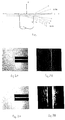
- This explosive division of the light forces the light waves to bend laterally through the fibre and in the air space behind the fibre, as can be explained with the aid of Huygens' principle. Bending of the light waves through the fibre causes certain light rays to move in directions other than straight through the fibre. Part of these light rays fall onto the limiting end face of the fibre. This end face delimits the fibre material with a refractive index n 2 against a thinner material, air, with a lower refractive index n 1 , resulting in total reflection; see Figure 1.
- the light is thereby divided into two different fields having mutually different phase conditions and in two mutually different wave fronts.
- the diffraction pattern is manifested as a central band of light followed by weaker parallel lines of light (diffraction lines), see Figures 2A, B, where Figure 2A illustrates a clean fibre end and Figure 2B shows the diffraction pattern that results from RE-interference.
- the central light line, first intensity maxima has been blocked out with the aid of a black band so that the weaker diffraction lines can be distinguished.
- the diffraction lines are a result of the interference between two secondary wave fronts formed after the diffraction of light through the fibre. Both wave fronts have their sources on the cylindrical fibre mantle according to Huygens' principle.
- Minute dust and dirt particles on the mantle surface of the fibre will function as irregular disturbance sources.
- These disturbance sources transmit secondary waves which are superimposed on the R-field and the E-field and form an irregular pattern that has a much greater contrast than the regular RE-diffraction pattern; see Figures 3A, B, where Figure 3A shows a dirty fibre end and Figure 3B shows a diffraction pattern deriving from the irregular interference.
- the central lighter line, first intensity maxima has been blocked out with the aid of a black band.
- the difference between this stochastic pattern from a dirty fibre end and the period pattern from a clean fibre end can be detected with the aid of a CCD camera.
- Figure 1 illustrates lateral spreading of light in accordance with Huygens' principle.
- Figures 2A, B show a clean fibre end and the diffraction pattern from the RE-interference.
- Figures 3A, B show a dirty fibre end and the diffraction pattern from the irregular interference.
- Figures 4A, B show dirt detection with the aid of laser light in accordance with the invention, from one side and from above respectively.
- FIGS 4A and 4B illustrate a system for detecting dirt with the aid of laser light from one side and from above respectively.
- a coherent light source e.g. an HeNe-laser or a diode laser, emits coherent light onto an optical fibre end 2.
- the light in the fibre end is collected by a collecting lens 3, such as a planar cylindrical lens placed between the light source and said fibre end.
- the resultant diffraction pattern is imaged on an incoherent semi-transparent screen 4.
- the area around the fibre end is illuminated orthogonally with the monochromic and coherent light, the diameter of the light beam being chosen so that the light will impinge on at least 0.5 mm of said fibre end.
- the incoherent semi-transparent screen is placed from the fibre end at a distance of at least 50 mm.
- a CCD camera 5 images and records the diffraction pattern from the other side of the screen.
- the cylindrical lens is used to enhance the intensity of the incident light when the intensity is not sufficient to form a clear diffraction pattern.
- Different cleanliness requirement levels can be defined, by comparing diffraction patterns from clean optic fibre ends.
- a dirt-warning system can be obtained with the aid of image analysis, e.g. by comparison with reference patterns on clean fibre ends, in which system the computer sends a signal to a monitoring unit when a dirty fibre end is detected, so as to enable appropriate remedial action to be taken.
- the computer and other equipment may be included in an automatic dirt-warning system provided, e.g., in a fibre-splicing machine, with the use of laser light diffraction to indicate dirt on fibre ends, wherewith a signal is sent to the fibre-splicing machine when dirt is detected on a fibre end, so as to prevent splicing of the dirty fibre end.
- an automatic dirt-warning system provided, e.g., in a fibre-splicing machine, with the use of laser light diffraction to indicate dirt on fibre ends, wherewith a signal is sent to the fibre-splicing machine when dirt is detected on a fibre end, so as to prevent splicing of the dirty fibre end.
Landscapes
- Physics & Mathematics (AREA)
- General Physics & Mathematics (AREA)
- Chemical & Material Sciences (AREA)
- Analytical Chemistry (AREA)
- General Health & Medical Sciences (AREA)
- Health & Medical Sciences (AREA)
- Life Sciences & Earth Sciences (AREA)
- Biochemistry (AREA)
- Immunology (AREA)
- Pathology (AREA)
- Optics & Photonics (AREA)
- Investigating Materials By The Use Of Optical Means Adapted For Particular Applications (AREA)
- Testing Of Optical Devices Or Fibers (AREA)
- Investigating Or Analysing Materials By Optical Means (AREA)
- Image Processing (AREA)
- Image Analysis (AREA)
- Mechanical Coupling Of Light Guides (AREA)
Applications Claiming Priority (2)
| Application Number | Priority Date | Filing Date | Title |
|---|---|---|---|
| SE9503365 | 1995-09-29 | ||
| SE9503365A SE504861C2 (sv) | 1995-09-29 | 1995-09-29 | Förfarande och anordning att detektera smuts på en optisk fiber |
Publications (2)
| Publication Number | Publication Date |
|---|---|
| EP0766082A1 true EP0766082A1 (de) | 1997-04-02 |
| EP0766082B1 EP0766082B1 (de) | 2005-01-19 |
Family
ID=20399630
Family Applications (1)
| Application Number | Title | Priority Date | Filing Date |
|---|---|---|---|
| EP96850153A Expired - Lifetime EP0766082B1 (de) | 1995-09-29 | 1996-09-19 | Methode und System zur Detektion von Schmutz an optischen Fasern |
Country Status (5)
| Country | Link |
|---|---|
| US (1) | US5748299A (de) |
| EP (1) | EP0766082B1 (de) |
| JP (1) | JP3828963B2 (de) |
| DE (1) | DE69634189T2 (de) |
| SE (1) | SE504861C2 (de) |
Cited By (2)
| Publication number | Priority date | Publication date | Assignee | Title |
|---|---|---|---|---|
| WO2013117497A1 (en) * | 2012-02-07 | 2013-08-15 | Tyco Electronics Raychem Bvba | Visually inspecting optical fibers |
| CN104076044A (zh) * | 2014-07-23 | 2014-10-01 | 南京吉隆光纤通信股份有限公司 | 一种光纤端面检测以及处理一体机 |
Families Citing this family (5)
| Publication number | Priority date | Publication date | Assignee | Title |
|---|---|---|---|---|
| US8208043B2 (en) * | 2008-05-09 | 2012-06-26 | Aptina Imaging Corporation | Lens cleaning warning system and method |
| US9082201B2 (en) | 2013-01-04 | 2015-07-14 | International Business Machines Corporation | Surface contamination determination system |
| US9645044B2 (en) | 2014-09-30 | 2017-05-09 | Corning Optical Communications LLC | Controlled-contact method of measuring insertion loss in optical fiber connectors |
| JP2018063160A (ja) | 2016-10-12 | 2018-04-19 | 富士通株式会社 | 検査装置および検査方法 |
| US12467824B2 (en) | 2020-07-21 | 2025-11-11 | Fujikura Ltd. | Inspection method for optical fiber, inspection device for optical fiber, and method for manufacturing optical fiber-wound bobbin |
Citations (3)
| Publication number | Priority date | Publication date | Assignee | Title |
|---|---|---|---|---|
| US4854701A (en) * | 1986-12-20 | 1989-08-08 | U.S. Philips Corp. | Arrangement for inspecting light waveguide end faces |
| EP0506401A2 (de) * | 1991-03-27 | 1992-09-30 | Hughes Aircraft Company | Automatisches Verfahren zum Einordnen der Fehler in optischer Faser |
| US5185636A (en) * | 1991-12-31 | 1993-02-09 | Corning Incorporated | Method for detecting defects in fibers |
Family Cites Families (2)
| Publication number | Priority date | Publication date | Assignee | Title |
|---|---|---|---|---|
| US4046536A (en) * | 1976-08-13 | 1977-09-06 | Western Electric Company, Inc. | Monitoring and control of optical fiber diameters |
| US5323225A (en) * | 1992-08-26 | 1994-06-21 | Andrew Corporation | Method of determining azimuthal position of transverse axes of optical fibers with elliptical cores |
-
1995
- 1995-09-29 SE SE9503365A patent/SE504861C2/sv unknown
-
1996
- 1996-09-12 US US08/710,187 patent/US5748299A/en not_active Expired - Lifetime
- 1996-09-19 DE DE69634189T patent/DE69634189T2/de not_active Expired - Lifetime
- 1996-09-19 EP EP96850153A patent/EP0766082B1/de not_active Expired - Lifetime
- 1996-09-27 JP JP25587996A patent/JP3828963B2/ja not_active Expired - Fee Related
Patent Citations (3)
| Publication number | Priority date | Publication date | Assignee | Title |
|---|---|---|---|---|
| US4854701A (en) * | 1986-12-20 | 1989-08-08 | U.S. Philips Corp. | Arrangement for inspecting light waveguide end faces |
| EP0506401A2 (de) * | 1991-03-27 | 1992-09-30 | Hughes Aircraft Company | Automatisches Verfahren zum Einordnen der Fehler in optischer Faser |
| US5185636A (en) * | 1991-12-31 | 1993-02-09 | Corning Incorporated | Method for detecting defects in fibers |
Cited By (3)
| Publication number | Priority date | Publication date | Assignee | Title |
|---|---|---|---|---|
| WO2013117497A1 (en) * | 2012-02-07 | 2013-08-15 | Tyco Electronics Raychem Bvba | Visually inspecting optical fibers |
| US10184858B2 (en) | 2012-02-07 | 2019-01-22 | CommScope Connectivity Belgium BVBA | Visually inspecting optical fibers |
| CN104076044A (zh) * | 2014-07-23 | 2014-10-01 | 南京吉隆光纤通信股份有限公司 | 一种光纤端面检测以及处理一体机 |
Also Published As
| Publication number | Publication date |
|---|---|
| DE69634189D1 (de) | 2005-02-24 |
| SE9503365D0 (sv) | 1995-09-29 |
| DE69634189T2 (de) | 2005-12-29 |
| JPH09145542A (ja) | 1997-06-06 |
| JP3828963B2 (ja) | 2006-10-04 |
| SE504861C2 (sv) | 1997-05-20 |
| EP0766082B1 (de) | 2005-01-19 |
| SE9503365L (sv) | 1997-03-30 |
| US5748299A (en) | 1998-05-05 |
Similar Documents
| Publication | Publication Date | Title |
|---|---|---|
| JP3226946B2 (ja) | 光学検査装置 | |
| CA1150541A (en) | Optical system with high coupling efficiency, in particular for attenuation measurement apparatuses employing the back-scattering technique | |
| US4972091A (en) | Method and apparatus for detecting the presence of flaws in a moving sheet of material | |
| JP3045629B2 (ja) | 凹凸パターン検出装置 | |
| US4854701A (en) | Arrangement for inspecting light waveguide end faces | |
| KR920006057B1 (ko) | 자기검사능력을 가진 광학섬유시스템 | |
| CN100387933C (zh) | 利用散斑图像处理技术检测和定位环境扰动的多光纤二维阵列装置 | |
| KR20000070453A (ko) | 레이저 기계가공 장치에 연결된 보호 글라스의 상태를 점검하는 방법 및 장치 | |
| WO2010104265A2 (ko) | 결점 검사를 위한 검사장치 | |
| KR900018643A (ko) | 삼각형법 광센서 및 그장치 | |
| EP0766082B1 (de) | Methode und System zur Detektion von Schmutz an optischen Fasern | |
| JP3248445B2 (ja) | 多心テープ光ファイバの表面異状検出方法および表面状態測定装置 | |
| JP3388285B2 (ja) | 検査装置 | |
| EP0244102B1 (de) | Vorrichtung zur Güteprüfung | |
| JPS5979137A (ja) | 光フアイバの断線検出方法 | |
| FR2548793A1 (fr) | Coupleur optique pour relier des fibres optiques | |
| HK35794A (en) | Method and apparatus for simultaneously observing a transparent object from two directions | |
| JP4403215B2 (ja) | 欠陥検査装置 | |
| JP2023163836A (ja) | 海苔異物確認装置 | |
| GB2054835A (en) | Scanning Apparatus for Flaw Detection | |
| EP0889337B1 (de) | Vorrichtung zur Abbildung optischer Faserbändchen | |
| JP3112219B2 (ja) | 移動検出方法及び検出器 | |
| JPH01202638A (ja) | 光ファイバ端面状態の検出方法及び検出装置 | |
| CA1295395C (en) | Method and apparatus for detecting the presence of flaws in a moving sheet of material | |
| EP0360232B1 (de) | Gerät zur Oberflächenprüfung |
Legal Events
| Date | Code | Title | Description |
|---|---|---|---|
| PUAI | Public reference made under article 153(3) epc to a published international application that has entered the european phase |
Free format text: ORIGINAL CODE: 0009012 |
|
| AK | Designated contracting states |
Kind code of ref document: A1 Designated state(s): DE FR GB IT |
|
| 17P | Request for examination filed |
Effective date: 19970929 |
|
| 17Q | First examination report despatched |
Effective date: 20030604 |
|
| RAP1 | Party data changed (applicant data changed or rights of an application transferred) |
Owner name: TELEFONAKTIEBOLAGET LM ERICSSON (PUBL) |
|
| GRAP | Despatch of communication of intention to grant a patent |
Free format text: ORIGINAL CODE: EPIDOSNIGR1 |
|
| GRAS | Grant fee paid |
Free format text: ORIGINAL CODE: EPIDOSNIGR3 |
|
| GRAA | (expected) grant |
Free format text: ORIGINAL CODE: 0009210 |
|
| AK | Designated contracting states |
Kind code of ref document: B1 Designated state(s): DE FR GB IT |
|
| REG | Reference to a national code |
Ref country code: GB Ref legal event code: FG4D |
|
| REF | Corresponds to: |
Ref document number: 69634189 Country of ref document: DE Date of ref document: 20050224 Kind code of ref document: P |
|
| PLBE | No opposition filed within time limit |
Free format text: ORIGINAL CODE: 0009261 |
|
| STAA | Information on the status of an ep patent application or granted ep patent |
Free format text: STATUS: NO OPPOSITION FILED WITHIN TIME LIMIT |
|
| ET | Fr: translation filed | ||
| 26N | No opposition filed |
Effective date: 20051020 |
|
| PGFP | Annual fee paid to national office [announced via postgrant information from national office to epo] |
Ref country code: IT Payment date: 20070926 Year of fee payment: 12 |
|
| PG25 | Lapsed in a contracting state [announced via postgrant information from national office to epo] |
Ref country code: IT Free format text: LAPSE BECAUSE OF NON-PAYMENT OF DUE FEES Effective date: 20080919 |
|
| REG | Reference to a national code |
Ref country code: FR Ref legal event code: PLFP Year of fee payment: 20 |
|
| PGFP | Annual fee paid to national office [announced via postgrant information from national office to epo] |
Ref country code: GB Payment date: 20150928 Year of fee payment: 20 |
|
| PGFP | Annual fee paid to national office [announced via postgrant information from national office to epo] |
Ref country code: FR Payment date: 20150917 Year of fee payment: 20 |
|
| PGFP | Annual fee paid to national office [announced via postgrant information from national office to epo] |
Ref country code: DE Payment date: 20150929 Year of fee payment: 20 |
|
| REG | Reference to a national code |
Ref country code: DE Ref legal event code: R071 Ref document number: 69634189 Country of ref document: DE |
|
| REG | Reference to a national code |
Ref country code: GB Ref legal event code: PE20 Expiry date: 20160918 |
|
| PG25 | Lapsed in a contracting state [announced via postgrant information from national office to epo] |
Ref country code: GB Free format text: LAPSE BECAUSE OF EXPIRATION OF PROTECTION Effective date: 20160918 |