EP0766233A2 - Magnetplattenantrieb - Google Patents
Magnetplattenantrieb Download PDFInfo
- Publication number
- EP0766233A2 EP0766233A2 EP96119067A EP96119067A EP0766233A2 EP 0766233 A2 EP0766233 A2 EP 0766233A2 EP 96119067 A EP96119067 A EP 96119067A EP 96119067 A EP96119067 A EP 96119067A EP 0766233 A2 EP0766233 A2 EP 0766233A2
- Authority
- EP
- European Patent Office
- Prior art keywords
- disk drive
- disks
- magnetic
- magnetic disk
- driving means
- Prior art date
- Legal status (The legal status is an assumption and is not a legal conclusion. Google has not performed a legal analysis and makes no representation as to the accuracy of the status listed.)
- Granted
Links
Images









Classifications
-
- G—PHYSICS
- G11—INFORMATION STORAGE
- G11B—INFORMATION STORAGE BASED ON RELATIVE MOVEMENT BETWEEN RECORD CARRIER AND TRANSDUCER
- G11B33/00—Constructional parts, details or accessories not provided for in the other groups of this subclass
- G11B33/12—Disposition of constructional parts in the apparatus, e.g. of power supply, of modules
- G11B33/121—Disposition of constructional parts in the apparatus, e.g. of power supply, of modules the apparatus comprising a single recording/reproducing device
-
- G—PHYSICS
- G11—INFORMATION STORAGE
- G11B—INFORMATION STORAGE BASED ON RELATIVE MOVEMENT BETWEEN RECORD CARRIER AND TRANSDUCER
- G11B19/00—Driving, starting, stopping record carriers not specifically of filamentary or web form, or of supports therefor; Control thereof; Control of operating function ; Driving both disc and head
- G11B19/20—Driving; Starting; Stopping; Control thereof
- G11B19/2009—Turntables, hubs and motors for disk drives; Mounting of motors in the drive
-
- G—PHYSICS
- G11—INFORMATION STORAGE
- G11B—INFORMATION STORAGE BASED ON RELATIVE MOVEMENT BETWEEN RECORD CARRIER AND TRANSDUCER
- G11B25/00—Apparatus characterised by the shape of record carrier employed but not specific to the method of recording or reproducing, e.g. dictating apparatus; Combinations of such apparatus
- G11B25/04—Apparatus characterised by the shape of record carrier employed but not specific to the method of recording or reproducing, e.g. dictating apparatus; Combinations of such apparatus using flat record carriers, e.g. disc, card
- G11B25/043—Apparatus characterised by the shape of record carrier employed but not specific to the method of recording or reproducing, e.g. dictating apparatus; Combinations of such apparatus using flat record carriers, e.g. disc, card using rotating discs
-
- G—PHYSICS
- G11—INFORMATION STORAGE
- G11B—INFORMATION STORAGE BASED ON RELATIVE MOVEMENT BETWEEN RECORD CARRIER AND TRANSDUCER
- G11B5/00—Recording by magnetisation or demagnetisation of a record carrier; Reproducing by magnetic means; Record carriers therefor
- G11B5/48—Disposition or mounting of heads or head supports relative to record carriers ; arrangements of heads, e.g. for scanning the record carrier to increase the relative speed
- G11B5/4806—Disposition or mounting of heads or head supports relative to record carriers ; arrangements of heads, e.g. for scanning the record carrier to increase the relative speed specially adapted for disk drive assemblies, e.g. assembly prior to operation, hard or flexible disk drives
- G11B5/4813—Mounting or aligning of arm assemblies, e.g. actuator arm supported by bearings, multiple arm assemblies, arm stacks or multiple heads on single arm
Definitions
- the present invention relates to a magnetic disk drive that can be utilized as an external memory of a computer. More specifically, it relates to the arrangement of various components of a magnetic disk drive within a disk enclosure.
- a magnetic disk drive having a number of magnetic disks utilized as recording media, has been in practical use in various regions including computer networks as one of the promising non-volatile memory devices. Furthermore, in recent years, the fabrication of a magnetic disk drive that satisfies the demand for a disk drive that is compatible, compact, inexpensive, has a large storage capacity, is light weight and has lower power consumption, has been required and has been in demand.
- a number of disks are arranged rotatably at high speed in a laminated manner with equally divided spaces and on the respective surfaces of the magnetic layers, recording media are formed concentrically. Further, in the vicinity of these disks, positioners are mounted and movable in the direction of the tracks of the disks, respectively, and supporting members are attached to the above positioners, respectively. Further, on the respective ends of the above supporting members, the reproducing/recording elements, e.g., magnetic heads are fixed in close proximity to the respective surfaces of the disks, so that the former can perform read/write operations for the tracks of the disks.
- each of the above supporting members have an arm that is fixed on each of the positioners.
- the base end portion of each suspension element is fastened to the tip portion of each arm with screws.
- the above suspension element is formed by a bending process of an extremely thin stainless steel sheet. Further, on both sides of the suspension element, bent portions are formed respectively to ensure the stiffness of the above suspension element.
- Each magnetic head is attached to the tip portion of each suspension element, via a gimbal.
- a printed board of various controlling circuits is usually positioned separately from the disk enclosure including the magnetic head, disks, etc.
- the above printed board is fixed on the bottom surface of the disk enclosure, i.e., outside the disk enclosure (for example, see U. S. Pat. No. 5025335 (Frederick M. Stefansky)). Therefore, taking into account the thickness of the printed board, the height of the whole disk drive becomes more significant (for example, approximately 15 mm). Consequently, because of the thickness of the printed circuit board, it is further difficult to promote compactibility in the disk drive.
- Integral Peripherals Inc. The construction of the above disk drive is similar to that of other disk drives and the height of the former disk drive is also approximately 15 mm as a whole. Integral Peripherals Inc. is further emphasizing that a thinner disk drive, as thin as 10 mm, can be realized by locating a printed circuit board on the side of a disk enclosure. In this case, though the thickness of the disk drive can be reduced, a new problem occurs in that the area of the disk drive including the printed circuit board and the disk enclosure is enlarged more than usual.
- EP 92305310.2 describes, inter alia, a flexible magnetic head, the use of which can significantly reduce the thickness of a disk drive.
- a disk drive comprises disks, a disk driving means that forces the disks to rotate, magnetic heads for performing read/write operations of the surfaces of the recording media of the disks, arms supporting the magnetic heads, positioners that support the arms rotatably, bearings that are arranged to allow the positioners to rotate, a positioner driving means that forces the positioners to rotate to move the magnetic heads to a predetermined position on the surface of recording media of the disks, a base and cover that constitute a disk enclosure in combination with each other, and circuits for controlling at least the disk driving means, read/write operations of the magnetic heads, the circuits being composed of a printed circuit board contained in the disk enclosure. Consequently the height of the magnetic disk drive can be less than 10.5 mm.
- the flexible unitary magnetic head described in the parent application can be used as the above magnetic head.
- the storage capacity of the disk drive can become greater than 120 MByte.
- a magnetic disk drive comprises the following components as a whole: two disks having a diameter of less than 1.8 inch, a disk driving means that forces the disks to rotate, four magnetic heads that perform read/write operations for the surfaces of recording media of the disks, arms that support the magnetic heads, positioners that support the arms rotatably, bearings that are arranged to allow the positioners to rotate, a positioner driving means that forces the positioners to rotate and make the magnetic heads move to a predetermined position on the surface of recording media of the fixed, a base and cover that constitute a disk enclosure in combination with each other; the disk enclosure protecting at least the disks, the disk driving means, the magnetic head, the arms, the positioners, the bearings and the positioner driving means, and circuits for controlling at least the disk driving means, read/write operations of the magnetic heads and the positioner driving means.
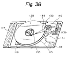
- the above circuits are composed of a flexible printed circuit board to be contained in the disk enclosure, and the height of the magnetic disk drive can be less than 10.5 mm. Further, the upper ends of shafts 113a, 113b are tightened to the cover 112 with screws.
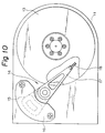
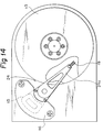
- two magnetic recording media (disks) 128 are supported and a spindle 120 is assembled. Further, on the other shaft 113b, positioners having actuators 130, magnetic heads 135 and arms 134 are supported. The above actuators 130 are adapted to move and maintain the magnetic heads 135 on the desired track of the disk 128.
- the printed circuit board 115 is arranged outside and around the spindle 120 to increase the utilisation of unoccupied space.
- a flexible printed circuit board denotes a flexible printed circuit board.
- This printed circuit board 115 is adhered and fixed to the inner surface of the base 111 and cover 112 with a releasable adhesive, etc.
- electronic circuit components 116 which is necessary for controlling the operation of whole disk drive (for example, servo control unit, DCM control unit, read/write unit, interface control unit and the like), are assembled.
- the printed circuit board 115 is connected to a connector 117 that is supported by the base 111 and cover 112. Further, the connector 117 is connected to the receptacle of external electronic equipment (for example, a portable note-type computer) and therefore the magnetic disk drive shown in Figs. 36 to 39 operates as a memory device of the above external electronic equipment.
- a spindle 120 is provided.
- the disk driving means has an in-spindle construction in which the hub of a DCM (direct current motor), i.e., the outer diameter of the rotor yoke, is approximately equal to the inner diameter of the magnetic recording media 128.
- 121 denotes a stator having laminated structure silicon steel sheets. Stator 121 is fixed to the shaft 113a by means of adhesion.
- the numeral 122 denotes a coil of copper wire wound around the stator 121. Lead wires (not shown in Figs. 36 to 39) extending from the coil 122 are connected to the respectively corresponding terminal on the printed circuit board 115 by means of soldering and therefore the current for driving the spindle 120 is supplied to the coil 122, via the lead wires.
- 123a denotes a lower bearing for magnetic recording media and 123b denotes a top bearing therefor.
- 124 denotes a spacer that maintains a constant gap between the lower bearing 123a and the top bearing 123b.
- the inner rings of the lower bearing 123a and the top bearing 123b are adhered and fixed to the shaft 113a.
- 125 denotes a hub or iron material. The inner peripheral portion of the hub 125 is adhered to the outer rings of the lower bearing 123a and the top bearing 123b.
- a magnet 126 is adhered to the stator 121, concentrically. Consequently, a magnetic circuit is formed by the stator 121, the hub 125 and the magnet 126.
- a driving force is induced in the above magnetic circuit to make the hub 125 rotate.
- Two sheets of magnetic recording medium 128 are held between a brim portion of the hub 125 and the spring ring 127, via a first spacer ring 129a and a second spacer ring 129b.
- 131a denotes a lower bearing for an actuator and 131b denotes a top bearing therefor.
- 132 denotes a spacer that maintains a constant gap between the rear bearing 131b and the top bearing 131b.
- the inner rings of the rear bearing 131a and the top bearing 131b are fixed to the shaft 113b.
- 133 denotes a block of aluminium material. The inner peripheral portion of the block 133 is adhered to the outer rings of the rear bearing 131a and the top bearing 131b.
- Each rim portion 133a is arranged on one corresponding end of each block 133. On the respective surfaces of the rim portions 133a, four arms are adhered and fixed, respectively.
- the magnetic recording media 128 are adhered to one end of the arms 134, respectively.
- the magnetic head 135 confronts the respectively corresponding surfaces of the magnetic recording area.
- the coil 136 is fixed firmly on each side of the block 133 opposite each rim portion 133a by resin molding.
- the 140 denotes a magnetic circuit that consists of a magnet 141 and a yoke of iron material 142.
- the above coil 136 is held in a magnetic air gap 143 of the magnetic circuit 140.
- the coil 136 is connected to the corresponding terminals on the printed circuit board 115, via an interconnecting means 116a, (for example, flexible printed circuit board) and the current is supplied to the coil 136.
- an interconnecting means 116a for example, flexible printed circuit board
- the actuator 130 moves rotationally around the shaft 113b.
- a track position signal indicating the present position of the magnetic head on the tracks, is issued from the magnetic head.
- the control circuit assembled on the printed circuit board controls the current that is supplied to the coil 136 and then moves and maintains the magnetic recording head 135 on the desired track of each magnetic recording medium 128.
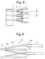
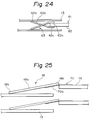
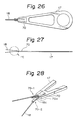
- an integrated unitary magnetic head shown in Figures 4 - 35 is preferably used as a magnetic head, to realize smaller dimensions.
- a conventional magnetic head such as a MIG magnetic head, can be used instead of the above unitary magnetic head.
- the lower and upper ends of a disk enclosure has usually has unoccupied space, except for the vicinity of the spindle and actuator. Therefore, the various circuits can be assembled on the above space and it becomes possible for the space in the disk enclosure to be utilized effectively. More concretely, the utilization of the unoccupied space in the disk enclosure can be realized by arranging a flexible printed circuit board in a position other than spindle, magnetic head, etc. and assembling the circuits on the above printed circuit.
- a disk enclosure is made of aluminium to lighten said enclosure and the rigid printed circuit board is mounted on the bottom surface of a base of the disk enclosure.
- the major part of various components of the disk drive is fabricated by press forming sheet metal. Therefore, an increase of the total weight can be minimized and the disk enclosure having an excellent shield effect and sufficient stiffness can be realized.
- the above disk drive can have the whole dimensions of approximately 85.6mm x 54.1mm x 10.4 mm (3.37 inch x 2.13 inch x 0.41 inch), similar to the conventional disk drive. Further, the above disk drive can have a total weight of less than 3 ounce (85g).
Landscapes
- Moving Of Heads (AREA)
- Supporting Of Heads In Record-Carrier Devices (AREA)
- Rotational Drive Of Disk (AREA)
Applications Claiming Priority (7)
| Application Number | Priority Date | Filing Date | Title |
|---|---|---|---|
| JP137884/91 | 1991-06-10 | ||
| JP3137884A JP2551700B2 (ja) | 1991-06-10 | 1991-06-10 | 磁気ディスク装置 |
| JP13788491 | 1991-06-10 | ||
| JP13884091 | 1991-06-11 | ||
| JP138840/91 | 1991-06-11 | ||
| JP3138840A JP2551701B2 (ja) | 1991-06-11 | 1991-06-11 | 磁気ディスク装置 |
| EP92305310A EP0518632B1 (de) | 1991-06-10 | 1992-06-10 | Magnetischer Plattenspeicher |
Related Parent Applications (2)
| Application Number | Title | Priority Date | Filing Date |
|---|---|---|---|
| EP92305310A Division EP0518632B1 (de) | 1991-06-10 | 1992-06-10 | Magnetischer Plattenspeicher |
| EP92305310.2 Division | 1992-06-10 |
Publications (3)
| Publication Number | Publication Date |
|---|---|
| EP0766233A2 true EP0766233A2 (de) | 1997-04-02 |
| EP0766233A3 EP0766233A3 (de) | 1998-01-07 |
| EP0766233B1 EP0766233B1 (de) | 2002-03-06 |
Family
ID=26471048
Family Applications (2)
| Application Number | Title | Priority Date | Filing Date |
|---|---|---|---|
| EP92305310A Expired - Lifetime EP0518632B1 (de) | 1991-06-10 | 1992-06-10 | Magnetischer Plattenspeicher |
| EP96119067A Expired - Lifetime EP0766233B1 (de) | 1991-06-10 | 1992-06-10 | Magnetplattenantrieb |
Family Applications Before (1)
| Application Number | Title | Priority Date | Filing Date |
|---|---|---|---|
| EP92305310A Expired - Lifetime EP0518632B1 (de) | 1991-06-10 | 1992-06-10 | Magnetischer Plattenspeicher |
Country Status (4)
| Country | Link |
|---|---|
| US (2) | US5572388A (de) |
| EP (2) | EP0518632B1 (de) |
| KR (1) | KR960001250B1 (de) |
| DE (2) | DE69223282T2 (de) |
Families Citing this family (6)
| Publication number | Priority date | Publication date | Assignee | Title |
|---|---|---|---|---|
| KR960001250B1 (ko) * | 1991-06-10 | 1996-01-24 | 후지쓰 가부시끼가이샤 | 자기 디스크드라이브 |
| SG44403A1 (en) * | 1993-02-26 | 1997-12-19 | Ibm | Rotating magnetic storage device |
| US6762906B1 (en) * | 1998-10-30 | 2004-07-13 | Iomega Corporation | Disk drive for removable disk cartridges and receivable into a PCMCIA port of a computer |
| WO2000074049A1 (en) * | 1999-05-27 | 2000-12-07 | Halo Data Devices, Inc. | Method and system for providing a disk drive in a compact flash form factor |
| US6826018B2 (en) * | 2001-03-06 | 2004-11-30 | Matsushita Electric Industrial Co., Ltd. | Disk drive with head supporting device |
| US7561445B2 (en) * | 2005-11-10 | 2009-07-14 | Nissan Motor Co., Ltd. | Harness routing structure for vehicle |
Citations (1)
| Publication number | Priority date | Publication date | Assignee | Title |
|---|---|---|---|---|
| US5025335A (en) | 1989-07-31 | 1991-06-18 | Conner Peripherals, Inc. | Architecture for 21/2 inch diameter single disk drive |
Family Cites Families (28)
| Publication number | Priority date | Publication date | Assignee | Title |
|---|---|---|---|---|
| US5119254A (en) * | 1980-09-24 | 1992-06-02 | Quantum Corporation | Data transducer position control system for rotating disk data storage equipment |
| JPS60182075A (ja) * | 1984-02-29 | 1985-09-17 | Fujitsu Ltd | 磁気ヘツド組立体の取付構造 |
| JPS6116080A (ja) * | 1984-07-02 | 1986-01-24 | Mitsubishi Electric Corp | 磁気デイスク装置 |
| JPS62185287A (ja) * | 1986-02-12 | 1987-08-13 | Hitachi Ltd | ハ−ドデイスク装置 |
| EP0432145B1 (de) * | 1986-06-04 | 1994-03-16 | Fujitsu Limited | Magnet-Scheibengerät |
| JPS63877A (ja) * | 1986-06-20 | 1988-01-05 | Mitsubishi Electric Corp | デイスク装置 |
| US4797762A (en) * | 1987-09-22 | 1989-01-10 | Micropolis Corporation | Stress free winchester drive shaft mounting |
| JPH01151001A (ja) * | 1987-12-09 | 1989-06-13 | Seiko Epson Corp | 磁気記憶装置 |
| US4991045A (en) * | 1987-12-21 | 1991-02-05 | Hutchinson Technology, Inc. | Suspension assembly |
| JPH01211282A (ja) * | 1988-02-17 | 1989-08-24 | Fujitsu Ltd | 磁気ディスク装置 |
| US4924337A (en) * | 1988-04-26 | 1990-05-08 | Miniscribe Corporation | Disk drive servo shield |
| EP0365807B1 (de) * | 1988-10-12 | 1993-12-22 | International Business Machines Corporation | Verbinden von metallischen Oberflächen |
| JP2843039B2 (ja) * | 1988-12-09 | 1999-01-06 | 株式会社日立製作所 | 磁気ディスク装置の組立方法 |
| JPH02162566A (ja) * | 1988-12-15 | 1990-06-22 | Canon Electron Inc | ディスク装置 |
| JPH02208815A (ja) * | 1989-02-08 | 1990-08-20 | Hitachi Ltd | 磁気記録再生装置の回転ヘッド装置 |
| US5109310A (en) * | 1989-03-07 | 1992-04-28 | Alps Electric Co., Ltd. | Disk drive device with unified actuator assembly |
| JP2858775B2 (ja) * | 1989-03-08 | 1999-02-17 | 株式会社日立製作所 | 磁気ヘッド支持装置及び磁気デイスク装置 |
| JPH0312882A (ja) * | 1989-06-09 | 1991-01-21 | Mitsubishi Electric Corp | 磁気ヘッド装置 |
| KR100232589B1 (ko) * | 1989-07-31 | 2000-01-15 | 토마스 에프.멀베니 | 기계적 트랙킹 이탈을 방지하기 위해 기억 디스크 및 액츄에이터의 장착점들과 정렬된 지지기둥들을 가지는 디스크 드라이브 |
| JPH0371417A (ja) * | 1989-08-10 | 1991-03-27 | Fujitsu Ltd | 磁気ディスク装置のキャリッジ |
| JPH0380480A (ja) * | 1989-08-23 | 1991-04-05 | Hitachi Ltd | 磁気ヘッド支持機構 |
| GB9016833D0 (en) * | 1989-09-19 | 1990-09-12 | Ibm | Disk storage apparatus |
| JPH03144978A (ja) * | 1989-10-31 | 1991-06-20 | Toshiba Corp | 磁気ディスク装置 |
| US5025336A (en) * | 1989-11-06 | 1991-06-18 | Prairietek Corporation | Disk drive apparatus |
| US5041932A (en) * | 1989-11-27 | 1991-08-20 | Censtor Corp. | Integrated magnetic read/write head/flexure/conductor structure |
| US5202804A (en) * | 1990-05-18 | 1993-04-13 | Kabushiki Kaisha Toshiba | Magnetic disk drive with a magnetic head rotationally actuated |
| EP0530217A4 (en) * | 1990-05-23 | 1993-09-08 | Conner Peripherals, Inc. | Thin line micro hard disk architecture |
| KR960001250B1 (ko) * | 1991-06-10 | 1996-01-24 | 후지쓰 가부시끼가이샤 | 자기 디스크드라이브 |
-
1992
- 1992-06-10 KR KR1019920010032A patent/KR960001250B1/ko not_active Expired - Fee Related
- 1992-06-10 EP EP92305310A patent/EP0518632B1/de not_active Expired - Lifetime
- 1992-06-10 DE DE69223282T patent/DE69223282T2/de not_active Expired - Fee Related
- 1992-06-10 DE DE69232468T patent/DE69232468T2/de not_active Expired - Fee Related
- 1992-06-10 EP EP96119067A patent/EP0766233B1/de not_active Expired - Lifetime
-
1994
- 1994-08-31 US US08/299,241 patent/US5572388A/en not_active Expired - Fee Related
-
1995
- 1995-10-27 US US08/549,033 patent/US5969907A/en not_active Expired - Fee Related
Patent Citations (2)
| Publication number | Priority date | Publication date | Assignee | Title |
|---|---|---|---|---|
| US5025335A (en) | 1989-07-31 | 1991-06-18 | Conner Peripherals, Inc. | Architecture for 21/2 inch diameter single disk drive |
| US5025335B1 (en) | 1989-07-31 | 1995-12-26 | Conner Peripherals Inc | Architecture for 2 1/2 inch diameter single disk drive |
Also Published As
| Publication number | Publication date |
|---|---|
| EP0766233A3 (de) | 1998-01-07 |
| EP0518632B1 (de) | 1997-11-26 |
| EP0518632A3 (en) | 1993-01-13 |
| EP0766233B1 (de) | 2002-03-06 |
| DE69232468T2 (de) | 2002-07-11 |
| DE69232468D1 (de) | 2002-04-11 |
| US5969907A (en) | 1999-10-19 |
| DE69223282T2 (de) | 1998-03-19 |
| US5572388A (en) | 1996-11-05 |
| KR960001250B1 (ko) | 1996-01-24 |
| DE69223282D1 (de) | 1998-01-08 |
| EP0518632A2 (de) | 1992-12-16 |
Similar Documents
| Publication | Publication Date | Title |
|---|---|---|
| US5898537A (en) | Storage device having an improved housing structure | |
| US6958890B1 (en) | Head stack assembly including laminated nut plate with damping layer interposed between metal layers | |
| US6765759B2 (en) | Resonance four piece suspension | |
| US6236531B1 (en) | Flex support snubber | |
| US5986852A (en) | High capacity, high performance low profile disk drive | |
| WO1997020310A1 (en) | Twin coil positioning device for use in a family of hard disk drives having interchangeable magnet components | |
| EP0556287B1 (de) | Architektur für hochleistungsplattenantrieb | |
| US5757582A (en) | Miniature hard disk drive system | |
| US5905608A (en) | Dynamically tuned outer arms for improved rotary actuator performance | |
| US6057990A (en) | Multiple actuator assemblies for data storage devices | |
| KR100201999B1 (ko) | 내충격 데이터 저장 시스템 액튜에이터 어셈블리 | |
| US11527262B2 (en) | Disk device having a multi-actuator assembly with a protective member attached to the tip of an actuator arm | |
| US5278709A (en) | Assembly of compact disk drive having a glass disk with a magnesium head arm assembly and a steel motor hub | |
| JPH01243278A (ja) | 磁気ディスク装置 | |
| EP0766233A2 (de) | Magnetplattenantrieb | |
| US5691861A (en) | Actuator arm assembly having side wall projection for carrying juxtaposed head wires | |
| Aruga et al. | High-speed orthogonal power effect actuator for recording at over 10000 TPI | |
| US6021025A (en) | Disk apparatus having an actuator for moving heads | |
| US5790344A (en) | Base casting/cover for separating pack bounce and spindle tilt modes in a magnetic storage system | |
| WO2004023486A1 (en) | A construction method and design for a magnetic head actuator mechanism | |
| US6549379B1 (en) | Unified disc drive top cover and voice coil motor pole | |
| US6731454B2 (en) | Disk drive with a pivot embedded torque generating track follow actuator and method therefor | |
| KR20050024255A (ko) | 서스펜션 조립체 및 자기 디스크 드라이브 | |
| WO1991018390A1 (en) | Thin line micro hard disk architecture | |
| JP3028252B2 (ja) | 磁気ディスク装置 |
Legal Events
| Date | Code | Title | Description |
|---|---|---|---|
| PUAI | Public reference made under article 153(3) epc to a published international application that has entered the european phase |
Free format text: ORIGINAL CODE: 0009012 |
|
| AC | Divisional application: reference to earlier application |
Ref document number: 518632 Country of ref document: EP |
|
| AK | Designated contracting states |
Kind code of ref document: A2 Designated state(s): DE FR GB |
|
| PUAL | Search report despatched |
Free format text: ORIGINAL CODE: 0009013 |
|
| AK | Designated contracting states |
Kind code of ref document: A3 Designated state(s): DE FR GB |
|
| 17P | Request for examination filed |
Effective date: 19980630 |
|
| 17Q | First examination report despatched |
Effective date: 19991029 |
|
| GRAG | Despatch of communication of intention to grant |
Free format text: ORIGINAL CODE: EPIDOS AGRA |
|
| GRAG | Despatch of communication of intention to grant |
Free format text: ORIGINAL CODE: EPIDOS AGRA |
|
| GRAH | Despatch of communication of intention to grant a patent |
Free format text: ORIGINAL CODE: EPIDOS IGRA |
|
| GRAH | Despatch of communication of intention to grant a patent |
Free format text: ORIGINAL CODE: EPIDOS IGRA |
|
| REG | Reference to a national code |
Ref country code: GB Ref legal event code: IF02 |
|
| GRAA | (expected) grant |
Free format text: ORIGINAL CODE: 0009210 |
|
| AC | Divisional application: reference to earlier application |
Ref document number: 518632 Country of ref document: EP |
|
| AK | Designated contracting states |
Kind code of ref document: B1 Designated state(s): DE FR GB |
|
| REF | Corresponds to: |
Ref document number: 69232468 Country of ref document: DE Date of ref document: 20020411 |
|
| ET | Fr: translation filed | ||
| PLBE | No opposition filed within time limit |
Free format text: ORIGINAL CODE: 0009261 |
|
| STAA | Information on the status of an ep patent application or granted ep patent |
Free format text: STATUS: NO OPPOSITION FILED WITHIN TIME LIMIT |
|
| 26N | No opposition filed |
Effective date: 20021209 |
|
| PGFP | Annual fee paid to national office [announced via postgrant information from national office to epo] |
Ref country code: GB Payment date: 20030604 Year of fee payment: 12 |
|
| PGFP | Annual fee paid to national office [announced via postgrant information from national office to epo] |
Ref country code: FR Payment date: 20030610 Year of fee payment: 12 |
|
| PGFP | Annual fee paid to national office [announced via postgrant information from national office to epo] |
Ref country code: DE Payment date: 20030618 Year of fee payment: 12 |
|
| PG25 | Lapsed in a contracting state [announced via postgrant information from national office to epo] |
Ref country code: GB Free format text: LAPSE BECAUSE OF NON-PAYMENT OF DUE FEES Effective date: 20040610 |
|
| PG25 | Lapsed in a contracting state [announced via postgrant information from national office to epo] |
Ref country code: DE Free format text: LAPSE BECAUSE OF NON-PAYMENT OF DUE FEES Effective date: 20050101 |
|
| GBPC | Gb: european patent ceased through non-payment of renewal fee |
Effective date: 20040610 |
|
| PG25 | Lapsed in a contracting state [announced via postgrant information from national office to epo] |
Ref country code: FR Free format text: LAPSE BECAUSE OF NON-PAYMENT OF DUE FEES Effective date: 20050228 |
|
| REG | Reference to a national code |
Ref country code: FR Ref legal event code: ST |