EP0766276B1 - Tastenanordnung - Google Patents
Tastenanordnung Download PDFInfo
- Publication number
- EP0766276B1 EP0766276B1 EP96306973A EP96306973A EP0766276B1 EP 0766276 B1 EP0766276 B1 EP 0766276B1 EP 96306973 A EP96306973 A EP 96306973A EP 96306973 A EP96306973 A EP 96306973A EP 0766276 B1 EP0766276 B1 EP 0766276B1
- Authority
- EP
- European Patent Office
- Prior art keywords
- key
- base
- contacts
- assembly according
- membrane
- Prior art date
- Legal status (The legal status is an assumption and is not a legal conclusion. Google has not performed a legal analysis and makes no representation as to the accuracy of the status listed.)
- Expired - Lifetime
Links
- 239000012528 membrane Substances 0.000 claims description 26
- 238000003780 insertion Methods 0.000 claims description 3
- 230000037431 insertion Effects 0.000 claims description 3
- 230000000712 assembly Effects 0.000 description 4
- 238000000429 assembly Methods 0.000 description 4
- 238000013461 design Methods 0.000 description 4
- 230000000994 depressogenic effect Effects 0.000 description 3
- 238000004519 manufacturing process Methods 0.000 description 2
- 239000004033 plastic Substances 0.000 description 2
- 229920003023 plastic Polymers 0.000 description 2
- 230000001154 acute effect Effects 0.000 description 1
- 238000013459 approach Methods 0.000 description 1
- 239000004020 conductor Substances 0.000 description 1
- 238000011161 development Methods 0.000 description 1
- 239000002184 metal Substances 0.000 description 1
- 238000000034 method Methods 0.000 description 1
- 230000000717 retained effect Effects 0.000 description 1
- 239000011435 rock Substances 0.000 description 1
Images


Classifications
-
- H—ELECTRICITY
- H01—ELECTRIC ELEMENTS
- H01H—ELECTRIC SWITCHES; RELAYS; SELECTORS; EMERGENCY PROTECTIVE DEVICES
- H01H13/00—Switches having rectilinearly-movable operating part or parts adapted for pushing or pulling in one direction only, e.g. push-button switch
- H01H13/70—Switches having rectilinearly-movable operating part or parts adapted for pushing or pulling in one direction only, e.g. push-button switch having a plurality of operating members associated with different sets of contacts, e.g. keyboard
- H01H13/78—Switches having rectilinearly-movable operating part or parts adapted for pushing or pulling in one direction only, e.g. push-button switch having a plurality of operating members associated with different sets of contacts, e.g. keyboard characterised by the contacts or the contact sites
- H01H13/80—Switches having rectilinearly-movable operating part or parts adapted for pushing or pulling in one direction only, e.g. push-button switch having a plurality of operating members associated with different sets of contacts, e.g. keyboard characterised by the contacts or the contact sites characterised by the manner of cooperation of the contacts, e.g. with both contacts movable or with bounceless contacts
-
- H—ELECTRICITY
- H01—ELECTRIC ELEMENTS
- H01H—ELECTRIC SWITCHES; RELAYS; SELECTORS; EMERGENCY PROTECTIVE DEVICES
- H01H13/00—Switches having rectilinearly-movable operating part or parts adapted for pushing or pulling in one direction only, e.g. push-button switch
- H01H13/70—Switches having rectilinearly-movable operating part or parts adapted for pushing or pulling in one direction only, e.g. push-button switch having a plurality of operating members associated with different sets of contacts, e.g. keyboard
- H01H13/702—Switches having rectilinearly-movable operating part or parts adapted for pushing or pulling in one direction only, e.g. push-button switch having a plurality of operating members associated with different sets of contacts, e.g. keyboard with contacts carried by or formed from layers in a multilayer structure, e.g. membrane switches
-
- H—ELECTRICITY
- H01—ELECTRIC ELEMENTS
- H01H—ELECTRIC SWITCHES; RELAYS; SELECTORS; EMERGENCY PROTECTIVE DEVICES
- H01H2201/00—Contacts
- H01H2201/008—Both contacts movable
-
- H—ELECTRICITY
- H01—ELECTRIC ELEMENTS
- H01H—ELECTRIC SWITCHES; RELAYS; SELECTORS; EMERGENCY PROTECTIVE DEVICES
- H01H2207/00—Connections
- H01H2207/012—Connections via underside of substrate
-
- H—ELECTRICITY
- H01—ELECTRIC ELEMENTS
- H01H—ELECTRIC SWITCHES; RELAYS; SELECTORS; EMERGENCY PROTECTIVE DEVICES
- H01H2221/00—Actuators
- H01H2221/024—Transmission element
- H01H2221/026—Guiding or lubricating nylon
-
- H—ELECTRICITY
- H01—ELECTRIC ELEMENTS
- H01H—ELECTRIC SWITCHES; RELAYS; SELECTORS; EMERGENCY PROTECTIVE DEVICES
- H01H2223/00—Casings
- H01H2223/034—Bezel
- H01H2223/0345—Bezel with keys positioned directly next to each other without an intermediate bezel or frame
-
- H—ELECTRICITY
- H01—ELECTRIC ELEMENTS
- H01H—ELECTRIC SWITCHES; RELAYS; SELECTORS; EMERGENCY PROTECTIVE DEVICES
- H01H2227/00—Dimensions; Characteristics
- H01H2227/036—Minimise height
-
- H—ELECTRICITY
- H01—ELECTRIC ELEMENTS
- H01H—ELECTRIC SWITCHES; RELAYS; SELECTORS; EMERGENCY PROTECTIVE DEVICES
- H01H2233/00—Key modules
- H01H2233/01—Key modules mounted on laykey
- H01H2233/014—Snap coupling
- H01H2233/016—Snap coupling with limited freedom
Definitions
- the invention relates to a low profile key assembly, for example for use in a key pad for portable computing equipment.
- EP 0453274 shows a key assembly also suitable for a desktop computer keyboard, according to the preamble of claim 1.
- EP 0453274 shows a key with a guide extending down from the base of a key; the guide passes through an aperture and ensures that the key is restrained to moving substantially vertically. There will inevitably be some tilting of the key if it is pressed off-center though, as the guide is itself deformable.
- the invention is a low profile key assembly, suitable for a portable computing device, comprises a base; the key being secured to, and mounted above the base by a resilient key mat having an upstanding wall, the key having a depending neck and being moveable against the resilience of the upstanding wall towards the base; a membrane supported on the base and carrying a pair of electrically insulated first contacts, each of the first contacts of the pair being connected to a respective electrical track supported on the membrane and extending to a connection location; and a second contact provided on an underside of either the depending neck or a portion of the key mat in contact with the depending neck and having a size and position such that movement of the key towards the base causes the second contact to engage both of the first contacts and thereby electrically connect the first contacts; wherein the resilient key mat (26) is common to multiple keys, and for each key, the key mat includes an upper, conical section (28) integrally formed with the upstanding wall (30) and with an inner surface 31 shaped to conform with an outer surface of the neck (18), the depending neck (18) being positioned on an
- depression of the key causes a conductor (the second contact), fixed relative to the guide itself, to bridge the contacts (the first contact pair) which are on a membrane underlying the key assembly; these contacts and all tracks may be placed on a common membrane (in contrast with U.S. Pat. No. 5,438,177 where separate membranes have to be used).
- the tracks are provided only on one side of the membrane but conveniently they are provided on both sides thus allowing more tracks to be accommodated.
- the invention enables key assemblies having heights of the order of 6 mm to be manufactured but in which the key travel distance is up to 1.2 mm. This results in a much more acceptable key assembly which can be incorporated into notebook or palmtop style computers.
- the key can itself rest on a deformable upstanding wall, which could have a cylindrical form but preferably is frusto-conical tapering inwardly from the base towards the key.
- the first contacts may be spaced about an arc, the second contact extending along the arc and, for example, the second contact could form a closed curve such as a circle.
- the membrane may be fully supported on the base but in the preferred arrangement, the part of the membrane carrying the first contacts overlies a recess in the base whereby movement of the key towards the base causes the membrane to be pushed against its resilience into the recess. This allows a certain amount of overtravel of the key to be permitted increasing the tactile response in a desirable manner.
- the recess will extend around the guide assembly and have a depth of substantially 0.15 mm.
- the upstanding wall of the resilient key mat is preferably continuous but instead could be defined by a set of circumferentially spaced legs.
- the advantage of a continuous wall is that the wall presents a substantially symmetrical resilience to the key.
- the key itself could be mounted to the key mat in a variety of ways. Typically, the neck of the key will be inserted into the cylindrical section of the key mat. The reverse arrangement is also possible.
- the guide assembly comprises a cooperating finger and socket, one on the base and the other on the key.
- the finger is mounted on the underside of the key and the socket is provided in the base. This arrangement is more easily manufactured than the reverse arrangement.
- connection between the key and the resilient key mat will provide a certain securement of the key in place but preferably one of the guide (or finger) and socket has a laterally extending lug and the other a resilient tab such that, on insertion of the finger into the socket, the lug snaps over the tab to retain the key on the guide assembly.
- the guide or finger could have a circular cross-section but in order to reduce twisting movement of the key it is preferred that the guide or finger and socket each have an interlocking form, for example a hexagonal or a cruciform cross-section.
- the key assembly according to the invention can be incorporated into a key pad having a number of such key assemblies and in this case, preferably the first electrical contacts of each of the keys are provided on a common membrane or printed circuit board, and preferably also the resilient key mats of each key are formed from a common resilient key mat.
- the key pad can be used in any conventional application of a key pad but is particularly suited for applications where the height of the keypad is critical as mentioned earlier.
- the computing equipment will include a processor connected to the first contact via the tracks so as to enable the location of a depressed key to be determined. This can be achieved in any conventional manner using conventional array scanning techniques which will be well known to persons of ordinary skill in the art.
- FIG. 1 illustrates a keypad 1 connected via a socket 2 to a processor 3 which in turn is connected to a display 4.
- the keypad includes a plastics base 5 which will typically form part of computing equipment in which the processor 3 and socket 2 are also housed. For clarity, the other parts of the computing equipment have been omitted.
- FIG. 1 typically, the elements shown in FIG. 1 will be housed within a notebook computer with the screen or display 4 hinged to the base of the keypad 5. Typical dimensions for such equipment when closed are 170 mm.times.90 mm.times.20 mm.
- the keypad 1 has a conventional arrangement of plastics keys arranged in five parallel rows. Certain keys have been omitted to enable the mounting arrangements 6 to be seen.
- FIG. 2 illustrates in cross-section the row of keys 7.
- the row comprises a "space " key 8 flanked on either side by keys 9-11 and 12-15 respectively.
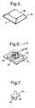
- the key 15 is shown in more detail in FIGS. 5 and 6. As can be seen, the key has a scalloped upper member 16 onto which the user's finger is placed in use and a four sided, outwardly tapering depending skirt 17 integrally formed with the member 16.
- the underside of the key 15 (FIG. 6) includes a circular depending neck 18 secured to the underside of the member 16 together with a depending finger 19 having a cruciform shape, the finger 19 being mounted centrally with respect to the key.
- the mounting arrangement of the key 15 is shown in more detail in the enlarged, partial cross-section of FIG. 3.
- the base 5 has an integrally formed boss 20 in which a bore 21 is formed.
- the bore 21 is shown in more detail in FIG. 7 and as can be seen has a cruciform shape corresponding to the shape of the finger 19.
- the finger 19 is located in the bore 21 and because of the matching cruciform shapes, cannot rotate relative to the bore 21.
- one of the legs 22 of the finger 19 is formed with a laterally extending lug 23 which fits into a corresponding slot 24 of the bore 21.
- a resilient tab 25 which will flex, on insertion of the finger 19 into the bore 21, when it engages with the lug 23 and then snap back behind the lug 23 so that the finger 19 is retained in the bore 21.
- the key 15 is supported above the base 5 by a resilient rubber mat 26 shown in more detail in FIG. 4.
- the mat 26 has an upstanding, frusto-conical portion 28 extending between a base portion 29 and an integrally formed circular portion 30.
- the circular portion 30 has an inner surface 31 shaped to conform with the outer surface of the neck 18 of the key 15 onto which it is push fitted.
- the frusto-conical portion 28 has sufficient resilience to hold the key 15 in the position shown in FIG. 3 above the base 5.
- the circular portion 30 supports on its under surface a circular, metal contact 32. Alternatively, as shown in FIG. 8, the contact 32 may be mounted on the underside of key 15.
- a printed circuit board 33 defines a membrane having a set of apertures 34 through which respective bosses of the base 5 extend. Extending partially about opposed sides of the apertures 34 are a pair of electrical contacts 35, 36 formed as arcs. For clarity, only the contacts 35,36 corresponding to the row 7 are shown. Each of the contacts 36 in the row 7 is electrically connected to a common track 37 provided on the upper surface of the membrane 33 and extending to a ribbon plug connector 39. It will be understood that the corresponding contacts in other rows will be connected to respective common tracks (not shown), each track extending to the connector 39 along the upper surface of the pcb 33.
- the contact 35 associated with the key 15 is connected to a track 38 provided on the underside of the membrane 33. Connection to the track 38 is achieved via a connector extending through a bore (not shown) in the membrane 33. The track 38 extends beneath the membrane 33 to the opposite side of the ribbon connector 39. Once again, it will be noted that the other contacts 35 will be connected to respective tracks (not shown) on the underside of the membrane 33.
- a circular recess 40 having a depth of 0.15 mm extends around each boss 20. It will be seen in FIG. 3 that part of the membrane 33 extends over the recess 40 and this part is directly beneath the contact 32 and carries the contacts 35,36 (not shown in FIG. 3).
- the frusto-conical section 28 of the rubber mat 26 will flex allowing the key 15 to be pushed downwardly towards the membrane 33. After travelling about 1.05 mm, the contact 32 engages the contacts 35,36 thus electrically connecting the contacts 35,36 together. Because the length of the finger 19 when the key is not depressed at all significantly exceeds the width of the bore 21, finger 19 slides smoothly down into the bore and will not jam even when the key 15 is pressed off center. As the key is pushed further, it will be pushed against the inherent resilience of the membrane 33, part of the membrane 33 being pushed into the recess 40. When the key 15 is released, the resilience of the frusto-conical section 28 will push the key 15 back up to the position shown in FIG. 3. The frusto-conical section 28 also provides a tactile feel during downward movement of the key 15.
- the processor 3 is connected via the socket 2 and ribbon connector 39 to the tracks 37,38 and polls the tracks in a regular manner to detect the electrical connection between any pair of contacts 35, 36 due to depression of a corresponding key. This information is then used by the processor in any conventional manner, for example to display an alpha-numeric character corresponding to the key on the display 4.
Landscapes
- Push-Button Switches (AREA)
- Input From Keyboards Or The Like (AREA)
Claims (13)
- Niedrigtastenanordnung, die für tragbare Rechnervorrichtungen geeignet ist, umfassend eine Unterlage (5); wobei die Taste (15) an der Unterlage (5) gesichert und über ihr mittels einer elastischen Tastenmatte (26) die eine aufrechte Wand (30) aufweist, montiert ist, wobei die Taste (15) einen abhängigen Hals (18) aufweist und gegen die Elastizität der aufrechten Wand (30) zur Unterlage (5) hin bewegbar ist; eine Führungsanordnung (19), die sich zwischen der Unterlage (5) und der Taste (15) erstreckt, um die Bewegung der Taste (15) zu führen; eine Membran (33), die auf der Unterlage (5) gestützt ist und ein Paar elektrisch isolierter erster Kontakte (35, 36) trägt, wobei jeder der ersten Kontakte des Paars jeweils mit einer elektrischen Bahn (37, 38) verbunden ist, welche auf der Membran (33) gestützt ist und sich zu einer Verbindungsstelle (39) hin erstreckt; und einen zweiten Kontakt (32), der auf einer Unterseite des abhängigen Halses (18) oder einem Abschnitt der Tastenmatte (26) mit dem abhängigen Hals (18) in Kontakt ist und eine Größe und Position aufweist, so dass die Bewegung der Taste (15) zu der Unterlage (5) hin bewirkt, dass der zweite Kontakt (32) in beide erste Kontakte (35, 36) eingreift und dadurch die ersten Kontakte (35, 36) elektrisch verbindet, wobei
die elastische Tastenmatte (26) mehreren Tasten gemein ist und die Tastenmatte für jede Taste einen oberen konischen Teilbereich (28) einschließt, der integral mit der aufrechten Wand (30) gebildet ist, wobei der konische. Teilbereich eine Innenfläche 31 aufweist, die so geformt ist, dass sie mit einer Außenfläche des Halses (18) konform ist, wobei der abhängige Hals (18) auf einer Unterseite der Taste (15) positioniert ist, wobei der abhängige Hals (18) um die Führungsanordnung (19) positioniert ist. - Tastenanordnung gemäß Anspruch 1, wobei die ersten Kontakte (35, 36) um einen Bogen herum mit Abstand angeordnet sind, wobei sich der zweite Kontakt (32) entlang dem Bogen erstreckt.
- Tastenanordnung gemäß Anspruch 2, wobei der zweite Kontakt (32) eine geschlossene Kurve bildet.
- Tastenanordnung gemäß Anspruch 3, wobei die geschlossene Kurve ein Kreis ist.
- Tastenanordnung gemäß Anspruch 4, wobei die ersten Kontakte (35, 36) um die Fassung (21) positioniert sind.
- Tastenanordnung gemäß Anspruch 1, wobei die Bahnen (37, 38) auf beiden Seiten der Membran (33) bereitgestellt sind.
- Tastenanordnung gemäß Anspruch 1, wobei ein Teil der Membran (33), welche den ersten Kontakt (35, 36) trägt, eine Aussparung (40) in der Unterlage überlagert, wodurch die Bewegung der Taste (15) zur Unterlage (5) hin bewirkt, dass die Membran (33) gegen die elastische Tastenmatte (26) in die Vertiefung (40) gedrückt wird.
- Tastenanordnung gemäß Anspruch 7, wobei die Vertiefung (40) sich um eine Nabe (20), welche die Fassung (21) umgibt, erstreckt.
- Tastenanordnung gemäß Anspruch 1, wobei die Führung ein Finger (19) mit einer Querschnittsform ist, welche verhindert, dass der Finger (19) sich in der Fassung (21) auf einer Ebene, die senkrecht zu der Richtung der Tastenvertiefung liegt, verdreht.
- Tastenanordnung gemäß Anspruch 11, wobei der Finger (19) einen kreuzförmigen Querschnitt aufweist.
- Tastenanordnung gemäß Anspruch 1, wobei entweder die Führung (19) oder die Fassung (21) einen sich lateral erstreckenden Ansatz (23) und die andere einen elastischen Lappen (25) aufweist, so dass beim Einführen der Führung (19) in die Fassung (21) der Ansatz (23) über dem Lappen (25) einrastet, um die Taste (15) zu halten.
- Tastenanordnung gemäß Anspruch 1, wobei der zweite Kontakt (32) auf einer Unterseite des abhängigen Halses (18) bereitgestellt ist.
- Ein tragbarer Computer, umfassend eine Niedrigtastenanordnung gemäß einem der vorhergehenden Ansprüche 1-12.
Applications Claiming Priority (2)
| Application Number | Priority Date | Filing Date | Title |
|---|---|---|---|
| GBGB9519557.4A GB9519557D0 (en) | 1995-09-26 | 1995-09-26 | Key assembly |
| GB9519557 | 1995-09-26 |
Publications (3)
| Publication Number | Publication Date |
|---|---|
| EP0766276A2 EP0766276A2 (de) | 1997-04-02 |
| EP0766276A3 EP0766276A3 (de) | 1998-04-29 |
| EP0766276B1 true EP0766276B1 (de) | 2007-07-18 |
Family
ID=10781246
Family Applications (1)
| Application Number | Title | Priority Date | Filing Date |
|---|---|---|---|
| EP96306973A Expired - Lifetime EP0766276B1 (de) | 1995-09-26 | 1996-09-25 | Tastenanordnung |
Country Status (5)
| Country | Link |
|---|---|
| US (1) | US5777281A (de) |
| EP (1) | EP0766276B1 (de) |
| JP (1) | JPH09120748A (de) |
| DE (1) | DE69637164T2 (de) |
| GB (1) | GB9519557D0 (de) |
Families Citing this family (25)
| Publication number | Priority date | Publication date | Assignee | Title |
|---|---|---|---|---|
| US6870730B2 (en) | 1995-09-26 | 2005-03-22 | Psion-Computers Plc | Computer with a pen or touch sensitive display |
| GB9622349D0 (en) * | 1996-10-28 | 1997-01-08 | Therefore Limited | Hand held computer and communications apparatus |
| US5990433A (en) * | 1997-12-17 | 1999-11-23 | Thomas & Betts International, Inc. | Molded electrical switch |
| US6057517A (en) * | 1999-02-23 | 2000-05-02 | Texas Industrial Peripherals | Elastomeric keyboard incorporating a novel interconnect and back-lighting architecture |
| TW434612B (en) * | 1999-07-27 | 2001-05-16 | Darfon Electronics Corp | Elastic thin layer of keyboard and its manufacturing method |
| US6781077B2 (en) | 2000-12-14 | 2004-08-24 | Think Outside, Inc. | Keyswitch and actuator structure |
| DE10113031B4 (de) * | 2001-03-17 | 2004-02-19 | Cimosys Ltd., St. Helier | Elektromotorischer Möbelantrieb zur Verstellung von Teilen eines Möbels relativ zueinender |
| JP4359812B2 (ja) * | 2002-07-08 | 2009-11-11 | 日本電気株式会社 | スイッチ一体型筐体およびこれを有する電子機器 |
| JP4046032B2 (ja) * | 2002-09-20 | 2008-02-13 | ヤマハ株式会社 | 照光式スイッチの構造、照光式スイッチ用の押しボタンユニット及び押下式スイッチの構造 |
| TWD113943S (zh) * | 2004-04-07 | 2006-11-21 | 明基電通股份有限公司 | 按鍵 |
| US7015678B2 (en) * | 2004-06-22 | 2006-03-21 | Dialog Semiconductor Gmbh | Efficiency improvement of DC-DC converter |
| DE102005014563A1 (de) * | 2005-03-02 | 2006-09-07 | Huf Hülsbeck & Fürst Gmbh & Co. Kg | Elektronischer Schlüssel |
| US7102093B1 (en) * | 2005-09-07 | 2006-09-05 | Cheng Uei Precision Industry Co., Ltd. | Key with binding structure |
| US7294799B2 (en) * | 2005-10-13 | 2007-11-13 | Ikey, Ltd. | Smooth keyboard with low key height |
| USD580936S1 (en) | 2007-01-31 | 2008-11-18 | Ikey, Ltd. | Keyboard |
| USD601557S1 (en) | 2007-08-06 | 2009-10-06 | Data Ltd., Inc. | Tablet computer |
| USD599349S1 (en) | 2008-07-14 | 2009-09-01 | Ikey, Ltd. | Keyboard |
| US8115126B2 (en) * | 2008-09-18 | 2012-02-14 | Stryker Corporation | Self-sealing control arrangement for a medical instrument |
| USD635568S1 (en) | 2009-06-09 | 2011-04-05 | Data Ltd., Inc. | Tablet computer |
| USD654499S1 (en) | 2009-06-09 | 2012-02-21 | Data Ltd., Inc. | Tablet computer |
| USD638834S1 (en) | 2009-10-05 | 2011-05-31 | Data Ltd., Inc. | Tablet computer |
| USD690296S1 (en) | 2011-02-01 | 2013-09-24 | Data Ltd., Inc. | Tablet computer |
| US8921720B2 (en) | 2011-04-25 | 2014-12-30 | Blackberry Limited | Apparatus and method pertaining to a key assembly having a plinth-receiving key mat |
| CA2815936A1 (en) | 2013-03-14 | 2014-09-14 | Stryker Corporation | Tamper-evident camera enclosure |
| CN110471561B (zh) * | 2019-02-21 | 2024-01-23 | 光宝电子(广州)有限公司 | 触控装置 |
Family Cites Families (11)
| Publication number | Priority date | Publication date | Assignee | Title |
|---|---|---|---|---|
| US3721778A (en) * | 1971-06-21 | 1973-03-20 | Chomerics Inc | Keyboard switch assembly with improved operator and contact structure |
| EP0322514A3 (de) * | 1987-12-30 | 1990-09-12 | Hewlett-Packard Company | Tastaturschalter |
| US4857683A (en) * | 1988-12-28 | 1989-08-15 | W. H. Brady Co. | Membrane switchcores with key cell contact elements connected together for continuous path testing |
| IT1232530B (it) * | 1989-06-29 | 1992-02-19 | Olivetti & Co Spa | Tastiera a contatti |
| US5115106A (en) * | 1990-04-20 | 1992-05-19 | Honeywell Inc. | Momentary "on" switch suitable for keyboards |
| JP2990224B2 (ja) * | 1991-02-27 | 1999-12-13 | 沖電気工業株式会社 | 押釦スイッチおよびその製造方法 |
| US5310973A (en) * | 1991-10-08 | 1994-05-10 | Silitek Corporation | Structure of key switch |
| US5438177A (en) * | 1992-05-06 | 1995-08-01 | Key Tronic Corporation | Two-layer membrane switch |
| US5298706A (en) * | 1992-08-13 | 1994-03-29 | Key Tronic Corporation | Membrane computer keyboard and improved key structure |
| US5386091A (en) * | 1993-04-08 | 1995-01-31 | Compaq Computer Corporation | Low profile keyswitch |
| US5525979A (en) * | 1995-08-14 | 1996-06-11 | Lexmark International, Inc. | Low configuration keyboard |
-
1995
- 1995-09-26 GB GBGB9519557.4A patent/GB9519557D0/en active Pending
-
1996
- 1996-09-23 US US08/723,881 patent/US5777281A/en not_active Expired - Fee Related
- 1996-09-25 JP JP8252559A patent/JPH09120748A/ja active Pending
- 1996-09-25 EP EP96306973A patent/EP0766276B1/de not_active Expired - Lifetime
- 1996-09-25 DE DE69637164T patent/DE69637164T2/de not_active Expired - Lifetime
Non-Patent Citations (1)
| Title |
|---|
| None * |
Also Published As
| Publication number | Publication date |
|---|---|
| JPH09120748A (ja) | 1997-05-06 |
| EP0766276A3 (de) | 1998-04-29 |
| EP0766276A2 (de) | 1997-04-02 |
| DE69637164T2 (de) | 2008-04-10 |
| US5777281A (en) | 1998-07-07 |
| DE69637164D1 (de) | 2007-08-30 |
| GB9519557D0 (en) | 1995-11-29 |
Similar Documents
| Publication | Publication Date | Title |
|---|---|---|
| US5777281A (en) | Key assembly | |
| US4687200A (en) | Multi-directional switch | |
| US5481074A (en) | Computer keyboard with cantilever switch and actuator design | |
| US5668358A (en) | Reconfigurable keyboard | |
| US4467150A (en) | Electronic keyboard | |
| US5917906A (en) | Touch pad with tactile feature | |
| US8581127B2 (en) | Key structure with scissors-type connecting member | |
| US4489227A (en) | Back lighted, full travel push button membrane keyboard | |
| US8278579B2 (en) | Thin key structure for keyboards/keypads | |
| EP0685860A1 (de) | Abgedichtete und Rückseitig beleuchtete Langhubtastatur | |
| CN100492265C (zh) | 手指可控制的多向开关 | |
| KR20040111692A (ko) | 키패드 및 키 스위치 | |
| US20110067990A1 (en) | Webbed keyboard assembly | |
| US5386091A (en) | Low profile keyswitch | |
| WO1999037025A1 (en) | Data entry device having multifunction keys | |
| US5504286A (en) | Multiple switch assembly including a rockable control plate for selectively actuating multiple microswitches | |
| US5694124A (en) | Portable computer with integrated circuit board and keyboard | |
| US5951178A (en) | Expandable and compressible keyboard | |
| US20100231518A1 (en) | Keyboard having multi-axis balance touch keys | |
| EP1577917A1 (de) | Tastaturen mit sowohl individuellen und kombinierten Ausgabetasten | |
| US20060119581A1 (en) | Keyboard improvements | |
| EP0423924B1 (de) | Langhubtastschalter mit verstärktem Benutzer-Feedback | |
| US20190148091A1 (en) | Luminous keyboard | |
| KR100743139B1 (ko) | 5방향 키 조작 장치 | |
| US20190131087A1 (en) | Keyboard device |
Legal Events
| Date | Code | Title | Description |
|---|---|---|---|
| PUAI | Public reference made under article 153(3) epc to a published international application that has entered the european phase |
Free format text: ORIGINAL CODE: 0009012 |
|
| AK | Designated contracting states |
Kind code of ref document: A2 Designated state(s): DE FR GB |
|
| PUAL | Search report despatched |
Free format text: ORIGINAL CODE: 0009013 |
|
| AK | Designated contracting states |
Kind code of ref document: A3 Designated state(s): DE FR GB |
|
| 17P | Request for examination filed |
Effective date: 19981109 |
|
| 17Q | First examination report despatched |
Effective date: 20010207 |
|
| GRAP | Despatch of communication of intention to grant a patent |
Free format text: ORIGINAL CODE: EPIDOSNIGR1 |
|
| GRAS | Grant fee paid |
Free format text: ORIGINAL CODE: EPIDOSNIGR3 |
|
| GRAA | (expected) grant |
Free format text: ORIGINAL CODE: 0009210 |
|
| AK | Designated contracting states |
Kind code of ref document: B1 Designated state(s): DE FR GB |
|
| REG | Reference to a national code |
Ref country code: GB Ref legal event code: FG4D |
|
| REF | Corresponds to: |
Ref document number: 69637164 Country of ref document: DE Date of ref document: 20070830 Kind code of ref document: P |
|
| ET | Fr: translation filed | ||
| PLBE | No opposition filed within time limit |
Free format text: ORIGINAL CODE: 0009261 |
|
| STAA | Information on the status of an ep patent application or granted ep patent |
Free format text: STATUS: NO OPPOSITION FILED WITHIN TIME LIMIT |
|
| 26N | No opposition filed |
Effective date: 20080421 |
|
| REG | Reference to a national code |
Ref country code: DE Ref legal event code: R082 Ref document number: 69637164 Country of ref document: DE Representative=s name: SCHUMACHER & WILLSAU PATENTANWALTSGESELLSCHAFT, DE Ref country code: DE Ref legal event code: R082 Ref document number: 69637164 Country of ref document: DE |
|
| REG | Reference to a national code |
Ref country code: DE Ref legal event code: R082 Ref document number: 69637164 Country of ref document: DE Representative=s name: SCHUMACHER & WILLSAU PATENTANWALTSGESELLSCHAFT, DE Effective date: 20130710 Ref country code: DE Ref legal event code: R081 Ref document number: 69637164 Country of ref document: DE Owner name: PSION HOLDINGS LTD., BASINGSTOKE, GB Free format text: FORMER OWNER: PSION PLC, LONDON, GB Effective date: 20130715 Ref country code: DE Ref legal event code: R081 Ref document number: 69637164 Country of ref document: DE Owner name: PSION HOLDINGS LTD., GB Free format text: FORMER OWNER: PSION PLC, LONDON, GB Effective date: 20130715 |
|
| REG | Reference to a national code |
Ref country code: FR Ref legal event code: CJ Effective date: 20130903 Ref country code: FR Ref legal event code: CD Owner name: PSION HOLDINGS LIMITED, GB Effective date: 20130903 Ref country code: FR Ref legal event code: CA Effective date: 20130903 |
|
| REG | Reference to a national code |
Ref country code: FR Ref legal event code: PLFP Year of fee payment: 20 |
|
| PGFP | Annual fee paid to national office [announced via postgrant information from national office to epo] |
Ref country code: GB Payment date: 20150825 Year of fee payment: 20 Ref country code: DE Payment date: 20150922 Year of fee payment: 20 |
|
| PGFP | Annual fee paid to national office [announced via postgrant information from national office to epo] |
Ref country code: FR Payment date: 20150824 Year of fee payment: 20 |
|
| REG | Reference to a national code |
Ref country code: DE Ref legal event code: R071 Ref document number: 69637164 Country of ref document: DE |
|
| REG | Reference to a national code |
Ref country code: GB Ref legal event code: PE20 Expiry date: 20160924 |
|
| PG25 | Lapsed in a contracting state [announced via postgrant information from national office to epo] |
Ref country code: GB Free format text: LAPSE BECAUSE OF EXPIRATION OF PROTECTION Effective date: 20160924 |