EP0766331B1 - Verfahren zur Herstellung eines Stromabnehmers in Kontakt mit einem Kathodenmaterial - Google Patents
Verfahren zur Herstellung eines Stromabnehmers in Kontakt mit einem Kathodenmaterial Download PDFInfo
- Publication number
- EP0766331B1 EP0766331B1 EP96111214A EP96111214A EP0766331B1 EP 0766331 B1 EP0766331 B1 EP 0766331B1 EP 96111214 A EP96111214 A EP 96111214A EP 96111214 A EP96111214 A EP 96111214A EP 0766331 B1 EP0766331 B1 EP 0766331B1
- Authority
- EP
- European Patent Office
- Prior art keywords
- cathode
- fact
- process according
- microns
- nickel
- Prior art date
- Legal status (The legal status is an assumption and is not a legal conclusion. Google has not performed a legal analysis and makes no representation as to the accuracy of the status listed.)
- Expired - Lifetime
Links
Images


Classifications
-
- H—ELECTRICITY
- H01—ELECTRIC ELEMENTS
- H01M—PROCESSES OR MEANS, e.g. BATTERIES, FOR THE DIRECT CONVERSION OF CHEMICAL ENERGY INTO ELECTRICAL ENERGY
- H01M10/00—Secondary cells; Manufacture thereof
- H01M10/05—Accumulators with non-aqueous electrolyte
- H01M10/052—Li-accumulators
-
- H—ELECTRICITY
- H01—ELECTRIC ELEMENTS
- H01M—PROCESSES OR MEANS, e.g. BATTERIES, FOR THE DIRECT CONVERSION OF CHEMICAL ENERGY INTO ELECTRICAL ENERGY
- H01M10/00—Secondary cells; Manufacture thereof
- H01M10/05—Accumulators with non-aqueous electrolyte
- H01M10/056—Accumulators with non-aqueous electrolyte characterised by the materials used as electrolytes, e.g. mixed inorganic/organic electrolytes
- H01M10/0564—Accumulators with non-aqueous electrolyte characterised by the materials used as electrolytes, e.g. mixed inorganic/organic electrolytes the electrolyte being constituted of organic materials only
- H01M10/0565—Polymeric materials, e.g. gel-type or solid-type
-
- H—ELECTRICITY
- H01—ELECTRIC ELEMENTS
- H01M—PROCESSES OR MEANS, e.g. BATTERIES, FOR THE DIRECT CONVERSION OF CHEMICAL ENERGY INTO ELECTRICAL ENERGY
- H01M4/00—Electrodes
- H01M4/02—Electrodes composed of, or comprising, active material
-
- H—ELECTRICITY
- H01—ELECTRIC ELEMENTS
- H01M—PROCESSES OR MEANS, e.g. BATTERIES, FOR THE DIRECT CONVERSION OF CHEMICAL ENERGY INTO ELECTRICAL ENERGY
- H01M4/00—Electrodes
- H01M4/02—Electrodes composed of, or comprising, active material
- H01M4/64—Carriers or collectors
-
- H—ELECTRICITY
- H01—ELECTRIC ELEMENTS
- H01M—PROCESSES OR MEANS, e.g. BATTERIES, FOR THE DIRECT CONVERSION OF CHEMICAL ENERGY INTO ELECTRICAL ENERGY
- H01M4/00—Electrodes
- H01M4/02—Electrodes composed of, or comprising, active material
- H01M2004/026—Electrodes composed of, or comprising, active material characterised by the polarity
- H01M2004/028—Positive electrodes
-
- Y—GENERAL TAGGING OF NEW TECHNOLOGICAL DEVELOPMENTS; GENERAL TAGGING OF CROSS-SECTIONAL TECHNOLOGIES SPANNING OVER SEVERAL SECTIONS OF THE IPC; TECHNICAL SUBJECTS COVERED BY FORMER USPC CROSS-REFERENCE ART COLLECTIONS [XRACs] AND DIGESTS
- Y02—TECHNOLOGIES OR APPLICATIONS FOR MITIGATION OR ADAPTATION AGAINST CLIMATE CHANGE
- Y02E—REDUCTION OF GREENHOUSE GAS [GHG] EMISSIONS, RELATED TO ENERGY GENERATION, TRANSMISSION OR DISTRIBUTION
- Y02E60/00—Enabling technologies; Technologies with a potential or indirect contribution to GHG emissions mitigation
- Y02E60/10—Energy storage using batteries
-
- Y—GENERAL TAGGING OF NEW TECHNOLOGICAL DEVELOPMENTS; GENERAL TAGGING OF CROSS-SECTIONAL TECHNOLOGIES SPANNING OVER SEVERAL SECTIONS OF THE IPC; TECHNICAL SUBJECTS COVERED BY FORMER USPC CROSS-REFERENCE ART COLLECTIONS [XRACs] AND DIGESTS
- Y02—TECHNOLOGIES OR APPLICATIONS FOR MITIGATION OR ADAPTATION AGAINST CLIMATE CHANGE
- Y02P—CLIMATE CHANGE MITIGATION TECHNOLOGIES IN THE PRODUCTION OR PROCESSING OF GOODS
- Y02P70/00—Climate change mitigation technologies in the production process for final industrial or consumer products
- Y02P70/50—Manufacturing or production processes characterised by the final manufactured product
-
- Y—GENERAL TAGGING OF NEW TECHNOLOGICAL DEVELOPMENTS; GENERAL TAGGING OF CROSS-SECTIONAL TECHNOLOGIES SPANNING OVER SEVERAL SECTIONS OF THE IPC; TECHNICAL SUBJECTS COVERED BY FORMER USPC CROSS-REFERENCE ART COLLECTIONS [XRACs] AND DIGESTS
- Y10—TECHNICAL SUBJECTS COVERED BY FORMER USPC
- Y10T—TECHNICAL SUBJECTS COVERED BY FORMER US CLASSIFICATION
- Y10T29/00—Metal working
- Y10T29/49—Method of mechanical manufacture
- Y10T29/49002—Electrical device making
- Y10T29/49108—Electric battery cell making
- Y10T29/49115—Electric battery cell making including coating or impregnating
Definitions
- the present invention concerns a process for the preparation of a current collector in contact with the cathode material in light, rechargeable, solid state batteries.
- Such batteries are generally constituted by a metal anode, preferably lithium, a ionically conducting polymeric electrolyte, a cathode based upon the oxide of a transition metal and a current collector in contact with the cathode material.
- the polymeric electrolyte is a ionic conducting, but non electronic polymer, with a dissolved salt of an alkali metal, preferably a lithium salt.
- the electrolyte acts as a reservoir of lithium ions, allows the passage of the charged particles between the two electrodes and also works as an electronic separator.
- amorphous comb-like polymers constituted by ethylene oxide chains bound to polymer backbones of methacrylate, phosphazene,siloxane, itaconate, vinyl ether type (US-A-4,886,716), or epoxide type (US-A-5,162,174), have a conductivity in the order of 10 -5 S/cm at 25°C.
- Metal aluminium, nickel, steel foils or metallized plastic foils are employed as current collectors. Metal nets can be adopted as well. The best performances in energetic terms of such systems are obtained when the electric contact between the cathode and the current collector is basically good.
- a problem which is often faced in this type of batteries is constituted by the necessity to have a good contact between the cathode and the current collector; a bad contact, in fact, involves an increase in the global resistance and some difficulty in the recharge of the battery.
- the present invention concerns a process for the preparation of a current collector in contact with the cathode material in light rechargeable solid state batteries, characterised by the fact that it includes the deposition on a nickel layer having a rugosity R a from 1 to 3 microns of a cathode paste comprising:
- the above-mentioned process is preferably followed by a step of rolling of the paste laid on the nickel collector, until one attains a cathode membrane of the desired thickness, preferably from 20 to 100 ⁇ m.
- the nickel layer of the desired rugosity is prepared by treating a nickel foil with a mixture of strong acids, for instance HF-HNO 3 , and then submitted to an etching treatment with plasma of argon. It will be shown in the experimental art that not all acid mixtures are equally effective in rendering the Nickel surface suited to this purpose.
- V 6 O 13 is a well known and commercially available material which can, for instance, be obtained by thermal decomposition of ammonium vadanate (NH 4 VO 3 ).
- carbon black is a commercial product, of which many types exist, such as, for instance, the Ketjen Black, the Super S. Carbon black is generally employed in a quantity ranging from 5% to 15% in weight as compared to the sum of 1 + 2 + 3.
- Both V 6 O 13 and carbon black must have, as is known to the experts in the branch, appropriate particle size, generally of some microns, an average diameter from 0.5 to 20 microns, approximately.
- the above-mentioned polymer is prepared starting from the two monomers (I) and (II) according to one of the procedures described in EP-A-638,950.
- the monomers (I) and (II), in a molar ratio from 98/2 to 40/60, are polymerized in the presence of LiBF 4 .
- the latter catalyzes the polymerisation in quantities from 0.5 to 4% in weight, preferably from 1 to 2% in weight, as compared to the sum of the monomers (I) and (II).
- the reaction of polymerisation is preferably carried out in the presence of a plasticizer, selected from dipolar aprotic solvents and low molecular weight polyethers and their relevant mixtures.
- a plasticizer selected from dipolar aprotic solvents and low molecular weight polyethers and their relevant mixtures.
- the above-mentioned plasticizers are selected among viscous liquids with a high dielectric constant ( ⁇ ), in order to grant a high dissociation of charges.
- Typical plasticizers are propylene carbonate (PC), ethylene carbonate (EC), dimethyl carbonate (DMC), diethyl carbonate (DEC), ⁇ -butyrolactone and their relevant mixtures.
- Another family of plasticizers are polyethers, such as, for instance, diglyme, tetraglyme and polyethers with a low molecular weight, having a lower dielectric constant, but a high stability to Lithium.
- the polymerisation preferably carried out at a temperature from 10 to 40°C (although the temperature of polymerisation does not prove binding), becomes complete in a time usually comprised between 0.5 and 10 hours, as a function of the percentage and of the ratio between the two monomers and of the lithium salt.
- the course of the reaction is easily monitored with an FT-IR analysis by following the disappearance of the vinyl band at 1620 cm -1 .
- the polymer thus formed eventually inglobing the plasticizer and the lithium salt, is colourless, transparent and does not drip.
- lithium salts are concerned, beside the LiBF 4 , which acts both as a polymerization catalyst and as an electrolyte, other lithium salts, such as LiCF 3 SO 3 , LiClO 4 , LiPF 6 , LiN(CF 3 SO 2 ) 2 , LiAsF 6 , can be present.
- the cathode paste is prepared in two steps, the first of which consists in preparing a dispersion in a dipolar aprotic solvent, preferably acetonitrile, of V 6 O 13 and carbon black.
- This dispersion with a contemporary reduction of the average diameter of the particles, is prepared by contemporaryly milling the two components in the presence of the inert solvent.
- one obtains a dispersion whose average diameter of the V 6 O 13 particles ranges from 1 to 6 ⁇ m and the average diameter of the carbon black particles ranges from 6 to 12 ⁇ m.
- This dispersion is subsequently added to the previously prepared polymeric gel, and the whole is homogenized, preferably by mixing it in moving containers which contain cylinders of an inert material.
- One provides, then, for the removal of the solvent contained in the cathode paste thus prepared, by using known techniques, preferably by evaporation of the solvent.
- a cathode paste without any solvent whose components are homogeneously dispersed, which shows a fluidity apt to be easily spread on the surface of the previously treated Nickel.
- EP 397523 discloses a process to prepare a cathode whereby a cathode paste containing a polymeric precursor is coated onto a microroughened current collector.
- the microroughened surface enables the cathode layer to tightly adhere to the current collector. This process however requires the need for an additional step of curing the cathode paste layer.
- a plastic material non adhesive foil such as, for instance, polyethylene or polypropylene
- the sandwich thus prepared nickel-cathode paste-polythene
- the plastic material foil is peeled away from the cathode surface; the thickness of the layer of the cathode material laid on the Nickel collector generally ranges from 20 to 100 microns, but it is even possible to obtain, where necessary, thicknesses of more than 100 microns.
- the rolling of the cathode on a current collector minimizes superficial irregularities, reduces, therefore, the impedance and allows a good contact between the cathode and the collector. This also allows to reduce the thickness of the cathode and to increase its utilisation.
- a typical cell can be assembled in the form of a thin layer, by superimposing an anode film, preferably Lithium, an electrolyte film and a cathode film, eventually laid down on a metal current collector.
- the lithium foil can be, for instance, rolled on a nickel foil, in order to grant the electric contact.
- the "sandwich" cell configuration thus obtained is particularly flexible and can be employed for the assembly of batteries, constituted by a certain number of cells in a series and/or a parallel connection, having various forms.
- the batteries can be obtained, for instance, by superimposing a certain number of elementary cells ("stack” configurations), or they can derive from the rolling of the thin layer (“rolling” configuration) or, finally, they can be obtained by folding the same thin layer (“concertina” configuration)
- stack a certain number of elementary cells
- electrtina a certain number of elementary cells
- they can derive from the rolling of the thin layer
- they can be obtained by folding the same thin layer
- concertina the same thin layer
- the cell is generally incapsulated by heat sealing, into a plastic container constituted by two layers, an internal one and an external one, of polyethylene or polypropylene, with an interposed alluminium foil (barrier coupled).
- the above-mentioned batteries attain a higher number of cycles as compared to the ones in the prior art.
- the compound with general formula (II), where m 3) (0.38 grams, 9.3% in weight) and the plasticizer, constituted (2.43 grams corresponding to 59.1% in weight) by a mixture 1/1 in weight of EC (ethylene carbonate) and TGME (tetraglyme), in which the two lithium salts LiCF 3 SO 3 (0.34 g, 8.2% in weight) and LiBF 4 (84 mg, 2% in weight on the total) are dissolved.
- EC ethylene carbonate
- TGME tetraglyme
- This second polymeric gel is obtained by mixing MVE (0.35 grams, 21% in weight), DVE (0.15 grams, 9% in weight) and the plasticizer, constituted by a mixture 1/1 in weight of PC (propylene carbonate) and TGME (1 gram, 60% in weight), which contains dissolved LiBF 4 (0.17 g, 10% in weight).
- the polymerisation and cross-linking of the system with the subsequent formation of the polymeric gel inglobing the lithium salt and the plasticizer is complete after about 2 hours.
- the powder of active cathode material V 6 O 13 is milled in a ceramic material ball mill for about 5 hours, thus obtaining powdery particles with an average diameter of 5 microns.
- the powder After the milling, the powder is dried in a vacuum at a temperature of about 100°C.
- the powder of electronic conductor ("Ketjen Black" carbon back of Akzo) is treated according to an analogous process. In this case the average diameter of the particles after the milling turns out to be of about 20 microns.
- V 6 O 13 (1.28 grams, 61.8% in weight) and carbon black (0.18 grams, 8.7% in weight) are put in a cylindric steel container together with acetonitrile (20 ml). The container is then filled with small cylinders of ceramic material, closed and agitated with a rotor for about 10 hours.
- the polymeric gel (0.61 grams, 29.5% in weight), described in Example 1 or 2, is added to the powder dispersion, having the aspect of a ink, and one maintains under agitation for still 3 hours.
- the cathode paste is recovered after the evaporation of the solvent.
- a foil of Nickel (of Teledyne Rodney Metal) having a thickness of 50 microns and a surface of 8X8 cm 2 is submitted to a chemical-physical cleaning treatment of the surface.
- the above-mentioned treatment consists in the degreasing of the surface with a hydrocarbon (hexane and/or pentane) solvent, followed by the immersion in a 50% aqueous solution of HF-HNO 3 , in a molar ratio of 1 over 2.
- a hydrocarbon hexane and/or pentane
- the Nickel foil is kept under immersion for a period of time varying from 3 to 5 minutes, then it is repeatedly washed with some distilled water and dried in a oven at 100°C in a vacuum.
- This first phase allows to clean the surface by eliminating any eventual trace of superficial oxides.
- the subsequent treatment of a physical type is carried out by argon plasma etching.
- the experimental conditions of power, pressure and time adopted are the following: Power: 100-200 Watts; Pressure: 35 mbars; Time: 30-60 seconds.
- the thickness of the nickel foil ranges from 30 to 40 microns, as a function of the time of permanence in the acid solution.
- the rugosity (R a ) of the nickel foil ranges from 1.2 to 1.6 microns.
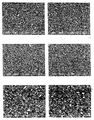
- Picture 1 is the electron microscope photograph of a nickel foil at the end of the above-described process
- picture 2 is the photograph of a non treated nickel foil (rugosity R a measured with a Mitutoyo Surf Test 500 instrument, from 0.2 to 0.4 ⁇ m).
- a certain quantity of cathode paste, obtained according to the process reported in example 3, is deposited on a nickel foil treated according to the process described in Example 4.
- a foil of plastic material (such as, for instance, polyethylene or polypropylene), which has no adhesive characteristics towards the cathode paste, is then laid on the cathode paste itself.
- the sandwich, constituted by nickel-cathode paste-polythene is then rolled at controlled thickness by using a roller.
- the polythene foil is then peeled away from the cathode surface. In this way, one obtains a thickness of the cathode membrane of 30 ⁇ m.
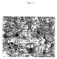
- a SEM analysis carried out on a specimen of composite cathode, with a composition analogous to the previous one, obtained by casting, by depositing on the nickel collector (being the latter treated according to the same process as the one described in example 4) the mixture of example 3 not as it is, but dispersed in acetonitrile and after the evaporation of the solvent, is reported by comparison; it is possible to point out the presence of holes which do not contain any active material and can represent discontinuity points in the path of Li+ ions inside the cathode.
- EXAMPLE 6A Assembly of an elementary cell, prepared according to the process of the present invention.
- a unipolar button cell with a surface equivalent to 1 cm 2 is prepared by superimposing, in the order:
- EXAMPLE 6B Assembly of an elementary cell, prepared according to the process of the present invention.
- a unipolar button cell with a surface equivalent to 1 cm 2 is prepared by superimposing, in the order:
- EXAMPLE 6C Assembly of an elementary cell, prepared according to the process of the present invention.
- a unipolar button cell with a surface equivalent to 1 cm 2 is prepared by superimposing, in the order:
- COMPARATIVE EXAMPLE 7 Assembly of an elementary cell with a non treated collector.
- a unipolar button cell with a surface equivalent to 1 cm 2 is prepared by superimposing, in the order:
- the cathode membrane (a) has a thickness of 130 microns, a weight of 28.1 mg (17.1 mg V 6 O 13 , 2.6 mg carbon black, 8.4 mg polymeric gel) and a capacity of 3.4 mAh (based upon the practical capacity of V 6 O 13 equivalent to 200 mAh/gr).
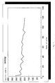
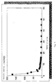
- picture 8 the specific capacity of the cell, cycled at a temperature of about 25°C, obtained at a constant charge and discharge current in the course of the cycles, and, in particular:
- COMPARATIVE EXAMPLE 8 Assembly of an elementary cell with a collector treated with HCl.
- the nickel colector is degreased with hydrocarbon solvents, then immersed in a 20% HCl aqueous solution.
- the nickel foil is kept under immersion for a period of time varying from 3 to 5 minutes, then it is repeatedly washed with some distilled water and dried in a oven at 100°C in a vacuum.
- a unipolar button cell with a surface equivalent to 1 cm 2 is prepared by superimposing, in the order:
Landscapes
- Chemical & Material Sciences (AREA)
- Chemical Kinetics & Catalysis (AREA)
- Electrochemistry (AREA)
- General Chemical & Material Sciences (AREA)
- Engineering & Computer Science (AREA)
- Manufacturing & Machinery (AREA)
- Physics & Mathematics (AREA)
- Condensed Matter Physics & Semiconductors (AREA)
- Dispersion Chemistry (AREA)
- General Physics & Mathematics (AREA)
- Inorganic Chemistry (AREA)
- Battery Electrode And Active Subsutance (AREA)
- Secondary Cells (AREA)
- Cell Electrode Carriers And Collectors (AREA)
- Primary Cells (AREA)
Claims (10)
- Verfahren zur Herstellung eines Kollektors in Kontakt mit dem Kathodenmaterial in leichten, wiederaufladbaren Feststoffbatterien, gekennzeichnet durch die Tatsache, daß es umfaßt die Abscheidung auf einer Nickelschicht mit einer Rauhigkeit Ra von 1 bis 3 Mikron von einer Kathodenpaste, umfassend:1) ein Pulver von aktivem Kathodenmaterial;2) einen Elektronenleiter;3) eine Polymerzusammensetzung, die im wesentlichen gebildet ist aus:3a) einem Polymer, abgeleitet aus der Polymerisation einer Mischung von einem Vinylether mit der allgemeinen Formel (I) R-[-O-CH2-CH2-]n-O-CH=CH2, worin R Methyl oder Ethyl bedeutet und n eine ganze Zahl zwischen 1 und 16 ist; und einem Divinylether mit der allgemeinen Formel (II) CH2=CH-[-O-CH2-CH2-]m-O-CH=CH2, worin m eine ganze Zahl zwischen 1 und 10 ist,3b) Lithiumsalzen, ausgewählt aus LiBF4 allein oder in einer Mischung mit anderen Salzen.
- Verfahren gemäß Anspruch 1, gekennzeichnet durch die Tatsache, daß die Polymerzusammensetzung 3) zusätzlich einen Weichmacher, ausgewählt aus dipolaren aprotischen Lösungsmitteln und niedermolekularen Lösungsmitteln und ihren relevanten Mischungen, umfaßt.
- Verfahren gemäß Anspruch 1, gekennzeichnet durch die Tatsache, daß die Nickelschicht eine Rauhigkeit im Bereich von 1,2 bis 1,6 Mikron aufweist.
- Verfahren gemäß Anspruch 1, gekennzeichnet durch die Tatsache, daß das aktive Kathodenmaterial im wesentlichen von V6O13 gebildet wird.
- Verfahren gemäß Anspruch 1, gekennzeichnet durch die Tatsache, daß der Elektronenleiter Ruß ist.
- Verfahren gemäß Anspruch 1, gekennzeichnet durch die Tatsache, daß das Molverhältnis zwischen dem Vinylether (I) und dem Divinylether (II) im Bereich von 98/2 bis 40/60 liegt.
- Verfahren gemäß Anspruch 1, gekennzeichnet durch die Tatsache, daß die Nickelfolie mit einer Rauhigkeit im Bereich von 1 bis 3 Mikron hergestellt wird, indem eine Nickelfolie einer Behandlung mit einer Mischung von HF/HNO3 unterworfen wird und anschließend mit Argonplasma geätzt wird.
- Verfahren gemäß irgendeinem der vorhergehenden Ansprüche, gekennzeichnet durch die Tatsache, daß es einen weiteren Schritt umfaßt, bei dem die auf den Kollektor aufgebrachte Paste gewalzt wird, bis man eine Kathodenmembran mit der gewünschten Dicke erhält.
- Verfahren gemäß Anspruch 8, gekennzeichnet durch die Tatsache, daß die Kathodenmembran eine Dicke von 20 bis 100 µm aufweist.
- Elektrochemische Zelle in Form einer dünnen Schicht, umfassend:gekennzeichnet durch die Tatsache, daß das Ensemble Kompositkathode - Kollektor gemäß irgendeinem der vorhergehenden Ansprüche hergestellt ist.a) eine Alkalimetallanode;b) einen ionisch leitenden polymeren Elektrolyten;c) eine auf einem Kollektor, der durch eine Nickelfolie gebildet ist, abgeschiedene Kompositkathode,
Applications Claiming Priority (2)
| Application Number | Priority Date | Filing Date | Title |
|---|---|---|---|
| ITMI951650 | 1995-07-28 | ||
| IT95MI001650A IT1277374B1 (it) | 1995-07-28 | 1995-07-28 | Procedimento per la preparazione di un collettore di corrente a contatto con il materiale catodico |
Publications (2)
| Publication Number | Publication Date |
|---|---|
| EP0766331A1 EP0766331A1 (de) | 1997-04-02 |
| EP0766331B1 true EP0766331B1 (de) | 1999-05-12 |
Family
ID=11372077
Family Applications (1)
| Application Number | Title | Priority Date | Filing Date |
|---|---|---|---|
| EP96111214A Expired - Lifetime EP0766331B1 (de) | 1995-07-28 | 1996-07-11 | Verfahren zur Herstellung eines Stromabnehmers in Kontakt mit einem Kathodenmaterial |
Country Status (6)
| Country | Link |
|---|---|
| US (1) | US5798190A (de) |
| EP (1) | EP0766331B1 (de) |
| JP (1) | JPH09223498A (de) |
| AT (1) | ATE180106T1 (de) |
| DE (1) | DE69602404T2 (de) |
| IT (1) | IT1277374B1 (de) |
Families Citing this family (17)
| Publication number | Priority date | Publication date | Assignee | Title |
|---|---|---|---|---|
| JP3387724B2 (ja) * | 1995-03-17 | 2003-03-17 | キヤノン株式会社 | 二次電池用電極、その製造方法及び該電極を有する二次電池 |
| KR19990025888A (ko) * | 1997-09-19 | 1999-04-06 | 손욱 | 리튬 계열 이차 전지용 극판의 제조 방법 |
| AU4544699A (en) * | 1998-06-08 | 1999-12-30 | Moltech Corporation | Polymerization of vinyl ethers |
| JP3573964B2 (ja) * | 1998-06-17 | 2004-10-06 | 三洋電機株式会社 | アルカリ電池用水素吸蔵合金電極及びアルカリ蓄電池用水素吸蔵合金電極の製造方法 |
| ATE268832T1 (de) * | 1999-09-08 | 2004-06-15 | Clariant Finance Bvi Ltd | Oberflächenveredlung von papier oder karton und mittel dafür |
| DE10030571C1 (de) * | 2000-06-21 | 2001-09-27 | Franz W Winterberg | Elektronisch leitfähiger Haftvermittler |
| DE10107384B4 (de) * | 2001-02-14 | 2007-02-08 | Dilo Trading Ag | Verwendung einer speziellen Polymers als Haftvermittler und Lithium-Polymer-Batterie |
| DE10232379B4 (de) * | 2002-07-17 | 2006-09-14 | Dilo Trading Ag | Elektrisch leitfähiger Haftvermittler, Elektrode, Verfahren zu deren Herstellung sowie Sekundärbatterie |
| JP5079329B2 (ja) * | 2003-08-01 | 2012-11-21 | バシウム・カナダ・インコーポレーテッド | ポリマー電池のための正極材料及びその製造方法 |
| DE102004035142A1 (de) | 2004-07-13 | 2006-02-02 | Varta Microbattery Gmbh | Galvanisches Element |
| EP2184799B1 (de) * | 2008-11-10 | 2013-01-09 | Samsung Electronics Co., Ltd. | Polymerelektrolyt, Lithiumbatterie mit dem Polymerelektrolyten, Herstellungsverfahren für den Polymerelektrolyten und Verfahren zur Herstellung der Lithiumbatterie |
| KR101669218B1 (ko) * | 2008-11-10 | 2016-11-10 | 삼성전자주식회사 | 겔 고분자 전해질, 이를 포함하는 리튬전지, 겔 고분자 전해질의 제조방법, 및 리튬전지의 제조방법 |
| US9601804B2 (en) | 2008-11-10 | 2017-03-21 | Samsung Electronics Co., Ltd. | Gel polymer electrolyte, lithium battery including gel polymer electrolyte, and method of preparing gel polymer electrolyte |
| US8951680B2 (en) * | 2011-03-08 | 2015-02-10 | Pellion Technologies, Inc. | Rechargeable magnesium ion cell components and assembly |
| US10707531B1 (en) | 2016-09-27 | 2020-07-07 | New Dominion Enterprises Inc. | All-inorganic solvents for electrolytes |
| CN116741980A (zh) * | 2022-03-02 | 2023-09-12 | 巴斯夫杉杉电池材料有限公司 | 一种锂离子电池用三元正极材料及其制备方法 |
| KR102831274B1 (ko) * | 2024-03-06 | 2025-07-10 | 한국에너지기술연구원 | 리튬 이차전지 전극 및 이의 제조방법 |
Family Cites Families (10)
| Publication number | Priority date | Publication date | Assignee | Title |
|---|---|---|---|---|
| US4460666A (en) * | 1981-11-24 | 1984-07-17 | Dinkler Leonard R | Coated substrate, preparation thereof, and use thereof |
| US4689475A (en) * | 1985-10-15 | 1987-08-25 | Raychem Corporation | Electrical devices containing conductive polymers |
| US4786499A (en) * | 1987-11-01 | 1988-11-22 | The United States Of America As Represented By The Secretary Of The Army | Lithium electrochemical cell including aprotic solvent-dialkyl carbonate solvent mixture |
| CA2016517C (en) * | 1989-05-11 | 1999-01-12 | Dale R. Shackle | Solid state electrochemical cell having microroughened current collector |
| US4935317A (en) * | 1989-06-21 | 1990-06-19 | Mhb Joint Venture | Method for producing solid state electrochemical laminar cell utilizing cathode rolling step |
| IT1244483B (it) * | 1990-12-21 | 1994-07-15 | Eniricerche Spa | Elettrolita polimerico solido a base di poliviniletere reticolato |
| JP2696011B2 (ja) * | 1991-08-01 | 1998-01-14 | 日本原子力研究所 | 電 池 |
| US5302474A (en) * | 1993-04-02 | 1994-04-12 | Valence Technology, Inc. | Fullerene-containing cathodes for solid electrochemical cells |
| DE69308836T2 (de) * | 1993-08-13 | 1997-09-11 | Eniricerche Spa | Verfahren zur Herstellung von festem Polymerelektrolyt auf Basis von Polyvinylethern |
| US5358801A (en) * | 1993-09-03 | 1994-10-25 | Valence Technology, Inc. | Solid electochemical cell of improved capacity and cycling capability having surfactant in vanadium oxide cathode mixture |
-
1995
- 1995-07-28 IT IT95MI001650A patent/IT1277374B1/it active IP Right Grant
-
1996
- 1996-07-11 AT AT96111214T patent/ATE180106T1/de not_active IP Right Cessation
- 1996-07-11 DE DE69602404T patent/DE69602404T2/de not_active Expired - Fee Related
- 1996-07-11 EP EP96111214A patent/EP0766331B1/de not_active Expired - Lifetime
- 1996-07-15 US US08/680,356 patent/US5798190A/en not_active Expired - Fee Related
- 1996-07-29 JP JP8199452A patent/JPH09223498A/ja active Pending
Also Published As
| Publication number | Publication date |
|---|---|
| ATE180106T1 (de) | 1999-05-15 |
| ITMI951650A1 (it) | 1997-01-28 |
| JPH09223498A (ja) | 1997-08-26 |
| IT1277374B1 (it) | 1997-11-10 |
| EP0766331A1 (de) | 1997-04-02 |
| ITMI951650A0 (it) | 1995-07-28 |
| US5798190A (en) | 1998-08-25 |
| DE69602404T2 (de) | 1999-09-16 |
| DE69602404D1 (de) | 1999-06-17 |
Similar Documents
| Publication | Publication Date | Title |
|---|---|---|
| EP0766331B1 (de) | Verfahren zur Herstellung eines Stromabnehmers in Kontakt mit einem Kathodenmaterial | |
| US5753388A (en) | Process for prelithiation of carbon based anodes for lithium ion electrochemical cells | |
| JP6163188B2 (ja) | 水溶性バインダーを含む水溶液から得られた薄膜により被覆された電極、その製造方法及び使用 | |
| KR101390057B1 (ko) | 비수전해질 이차 전지 및 그의 제조 방법 | |
| US5962170A (en) | Electrochemical cell | |
| JP5207687B2 (ja) | シラン化合物を含む有機電解液及びリチウム電池 | |
| US6051343A (en) | Polymeric solid electrolyte and lithium secondary cell using the same | |
| US20040043295A1 (en) | Rechargeable composite polymer battery | |
| JP2006506775A5 (de) | ||
| WO1999003162A1 (en) | Stabilized anode for lithium-polymer batteries | |
| EP2113957A1 (de) | Positive Elektrode für Lithiumsekundärzelle und Lithiumsekundärzelle damit | |
| EP3866225A1 (de) | Anode und lithiumsekundärbatterie damit | |
| EP2453511A1 (de) | Polymergelelektrolyt und polymer-akkumulator damit | |
| JP2001357883A (ja) | ゲル状の電解液およびこれを用いたリチウム電池 | |
| JP2002319405A (ja) | リチウム二次電池 | |
| JPH079818B2 (ja) | 非水性アルカリ電池 | |
| US5756231A (en) | Composite cathode, process for its preparation and its use in solid electrolytic cells | |
| WO1997019477A1 (en) | CATHODE-ACTIVE MATERIAL BLENDS OF LixMn2O4 AND Liy-α-MnO¿2? | |
| JP4053657B2 (ja) | リチウム二次電池及びその製造方法 | |
| JP2003173782A (ja) | リチウム二次電池及び正極 | |
| JP2002216744A (ja) | 非水電解質電池および非水電解質電池用正極の製造法。 | |
| EP0905807B1 (de) | Nichtwässrige Sekundärbatterie | |
| US5738691A (en) | Ultrasonic extraction of plasticizer from electrochemical cells | |
| JP2005026091A (ja) | 非水電解質電池 | |
| EP0404578A1 (de) | Sekundärbatterie |
Legal Events
| Date | Code | Title | Description |
|---|---|---|---|
| PUAI | Public reference made under article 153(3) epc to a published international application that has entered the european phase |
Free format text: ORIGINAL CODE: 0009012 |
|
| AK | Designated contracting states |
Kind code of ref document: A1 Designated state(s): AT CH DE FR GB LI NL SE |
|
| 17P | Request for examination filed |
Effective date: 19970811 |
|
| 17Q | First examination report despatched |
Effective date: 19980218 |
|
| RAP1 | Party data changed (applicant data changed or rights of an application transferred) |
Owner name: OLIVETTI S.P.A. Owner name: ENITECNOLOGIE S.P.A. |
|
| GRAG | Despatch of communication of intention to grant |
Free format text: ORIGINAL CODE: EPIDOS AGRA |
|
| GRAG | Despatch of communication of intention to grant |
Free format text: ORIGINAL CODE: EPIDOS AGRA |
|
| GRAH | Despatch of communication of intention to grant a patent |
Free format text: ORIGINAL CODE: EPIDOS IGRA |
|
| GRAH | Despatch of communication of intention to grant a patent |
Free format text: ORIGINAL CODE: EPIDOS IGRA |
|
| GRAA | (expected) grant |
Free format text: ORIGINAL CODE: 0009210 |
|
| AK | Designated contracting states |
Kind code of ref document: B1 Designated state(s): AT CH DE FR GB LI NL SE |
|
| REF | Corresponds to: |
Ref document number: 180106 Country of ref document: AT Date of ref document: 19990515 Kind code of ref document: T |
|
| REG | Reference to a national code |
Ref country code: CH Ref legal event code: NV Representative=s name: KIRKER & CIE SA Ref country code: CH Ref legal event code: EP |
|
| REF | Corresponds to: |
Ref document number: 69602404 Country of ref document: DE Date of ref document: 19990617 |
|
| ET | Fr: translation filed | ||
| PLBE | No opposition filed within time limit |
Free format text: ORIGINAL CODE: 0009261 |
|
| STAA | Information on the status of an ep patent application or granted ep patent |
Free format text: STATUS: NO OPPOSITION FILED WITHIN TIME LIMIT |
|
| 26N | No opposition filed | ||
| PGFP | Annual fee paid to national office [announced via postgrant information from national office to epo] |
Ref country code: DE Payment date: 20010702 Year of fee payment: 6 |
|
| PGFP | Annual fee paid to national office [announced via postgrant information from national office to epo] |
Ref country code: SE Payment date: 20010704 Year of fee payment: 6 |
|
| PGFP | Annual fee paid to national office [announced via postgrant information from national office to epo] |
Ref country code: GB Payment date: 20010711 Year of fee payment: 6 Ref country code: AT Payment date: 20010711 Year of fee payment: 6 |
|
| PGFP | Annual fee paid to national office [announced via postgrant information from national office to epo] |
Ref country code: FR Payment date: 20010712 Year of fee payment: 6 |
|
| PGFP | Annual fee paid to national office [announced via postgrant information from national office to epo] |
Ref country code: CH Payment date: 20010713 Year of fee payment: 6 |
|
| PGFP | Annual fee paid to national office [announced via postgrant information from national office to epo] |
Ref country code: NL Payment date: 20010730 Year of fee payment: 6 |
|
| REG | Reference to a national code |
Ref country code: GB Ref legal event code: IF02 |
|
| PG25 | Lapsed in a contracting state [announced via postgrant information from national office to epo] |
Ref country code: GB Free format text: LAPSE BECAUSE OF NON-PAYMENT OF DUE FEES Effective date: 20020711 Ref country code: AT Free format text: LAPSE BECAUSE OF NON-PAYMENT OF DUE FEES Effective date: 20020711 |
|
| PG25 | Lapsed in a contracting state [announced via postgrant information from national office to epo] |
Ref country code: SE Free format text: LAPSE BECAUSE OF NON-PAYMENT OF DUE FEES Effective date: 20020712 |
|
| PG25 | Lapsed in a contracting state [announced via postgrant information from national office to epo] |
Ref country code: LI Free format text: LAPSE BECAUSE OF NON-PAYMENT OF DUE FEES Effective date: 20020731 Ref country code: CH Free format text: LAPSE BECAUSE OF NON-PAYMENT OF DUE FEES Effective date: 20020731 |
|
| PG25 | Lapsed in a contracting state [announced via postgrant information from national office to epo] |
Ref country code: NL Free format text: LAPSE BECAUSE OF NON-PAYMENT OF DUE FEES Effective date: 20030201 Ref country code: DE Free format text: LAPSE BECAUSE OF NON-PAYMENT OF DUE FEES Effective date: 20030201 |
|
| EUG | Se: european patent has lapsed | ||
| GBPC | Gb: european patent ceased through non-payment of renewal fee |
Effective date: 20020711 |
|
| REG | Reference to a national code |
Ref country code: CH Ref legal event code: PL |
|
| PG25 | Lapsed in a contracting state [announced via postgrant information from national office to epo] |
Ref country code: FR Free format text: LAPSE BECAUSE OF NON-PAYMENT OF DUE FEES Effective date: 20030331 |
|
| NLV4 | Nl: lapsed or anulled due to non-payment of the annual fee |
Effective date: 20030201 |
|
| REG | Reference to a national code |
Ref country code: FR Ref legal event code: ST |