EP0766340A2 - Oberflächenmontierbare Antenne und Kommunikationsgerät mit einer derartigen Antenne - Google Patents
Oberflächenmontierbare Antenne und Kommunikationsgerät mit einer derartigen Antenne Download PDFInfo
- Publication number
- EP0766340A2 EP0766340A2 EP96115315A EP96115315A EP0766340A2 EP 0766340 A2 EP0766340 A2 EP 0766340A2 EP 96115315 A EP96115315 A EP 96115315A EP 96115315 A EP96115315 A EP 96115315A EP 0766340 A2 EP0766340 A2 EP 0766340A2
- Authority
- EP
- European Patent Office
- Prior art keywords
- electrode
- substrate
- disposed
- lateral surface
- radiation electrode
- Prior art date
- Legal status (The legal status is an assumption and is not a legal conclusion. Google has not performed a legal analysis and makes no representation as to the accuracy of the status listed.)
- Granted
Links
- 238000004891 communication Methods 0.000 title claims abstract description 12
- 230000005855 radiation Effects 0.000 claims abstract description 73
- 239000000758 substrate Substances 0.000 claims abstract description 56
- 239000003990 capacitor Substances 0.000 claims abstract description 30
- 230000015572 biosynthetic process Effects 0.000 abstract description 3
- 238000005452 bending Methods 0.000 abstract 1
- 238000010276 construction Methods 0.000 description 3
- 230000002708 enhancing effect Effects 0.000 description 3
- 230000001413 cellular effect Effects 0.000 description 1
- 230000003247 decreasing effect Effects 0.000 description 1
- 239000003989 dielectric material Substances 0.000 description 1
- 230000000694 effects Effects 0.000 description 1
- 239000000696 magnetic material Substances 0.000 description 1
- 238000010295 mobile communication Methods 0.000 description 1
- 238000012986 modification Methods 0.000 description 1
- 230000004048 modification Effects 0.000 description 1
- 238000005476 soldering Methods 0.000 description 1
Images


Classifications
-
- H—ELECTRICITY
- H01—ELECTRIC ELEMENTS
- H01Q—ANTENNAS, i.e. RADIO AERIALS
- H01Q1/00—Details of, or arrangements associated with, antennas
- H01Q1/12—Supports; Mounting means
- H01Q1/22—Supports; Mounting means by structural association with other equipment or articles
- H01Q1/2283—Supports; Mounting means by structural association with other equipment or articles mounted in or on the surface of a semiconductor substrate as a chip-type antenna or integrated with other components into an IC package
-
- H—ELECTRICITY
- H01—ELECTRIC ELEMENTS
- H01Q—ANTENNAS, i.e. RADIO AERIALS
- H01Q1/00—Details of, or arrangements associated with, antennas
- H01Q1/12—Supports; Mounting means
- H01Q1/22—Supports; Mounting means by structural association with other equipment or articles
- H01Q1/24—Supports; Mounting means by structural association with other equipment or articles with receiving set
- H01Q1/241—Supports; Mounting means by structural association with other equipment or articles with receiving set used in mobile communications, e.g. GSM
- H01Q1/242—Supports; Mounting means by structural association with other equipment or articles with receiving set used in mobile communications, e.g. GSM specially adapted for hand-held use
- H01Q1/243—Supports; Mounting means by structural association with other equipment or articles with receiving set used in mobile communications, e.g. GSM specially adapted for hand-held use with built-in antennas
-
- H—ELECTRICITY
- H01—ELECTRIC ELEMENTS
- H01Q—ANTENNAS, i.e. RADIO AERIALS
- H01Q1/00—Details of, or arrangements associated with, antennas
- H01Q1/36—Structural form of radiating elements, e.g. cone, spiral, umbrella; Particular materials used therewith
-
- H—ELECTRICITY
- H01—ELECTRIC ELEMENTS
- H01Q—ANTENNAS, i.e. RADIO AERIALS
- H01Q1/00—Details of, or arrangements associated with, antennas
- H01Q1/36—Structural form of radiating elements, e.g. cone, spiral, umbrella; Particular materials used therewith
- H01Q1/38—Structural form of radiating elements, e.g. cone, spiral, umbrella; Particular materials used therewith formed by a conductive layer on an insulating support
-
- H—ELECTRICITY
- H01—ELECTRIC ELEMENTS
- H01Q—ANTENNAS, i.e. RADIO AERIALS
- H01Q9/00—Electrically-short antennas having dimensions not more than twice the operating wavelength and consisting of conductive active radiating elements
- H01Q9/04—Resonant antennas
- H01Q9/0407—Substantially flat resonant element parallel to ground plane, e.g. patch antenna
- H01Q9/0421—Substantially flat resonant element parallel to ground plane, e.g. patch antenna with a shorting wall or a shorting pin at one end of the element
Definitions
- the present invention relates to a surface mounting antenna for use in mobile communication apparatus, such as mobile cellular telephones and radio Local Area Networks (LAN).
- the invention also relates to a communication apparatus using the above type of antenna.
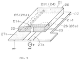
- a typical surface mounting antenna of a known type generally indicated by 20 has a substrate 21.
- a ground terminal 22 and part of a feeding terminal 23 are disposed on one lateral surface 21a of the substrate 21.
- the remaining feeding terminal 23 is provided on another lateral surface 21c adjacent to the lateral surface 21a.
- a loading capacitor electrode 24 is disposed on a lateral surface 21b opposedly facing the lateral surface 21a.
- a through hole 25 is formed between the opposedly-facing surfaces 21a and 21b so as to receive a radiation electrode 25a therein.
- This radiation electrode 25a is electrically connected to both the ground terminal 22 and the loading capacitor electrode 24.
- a through hole 26 is formed from the lateral surface 21c to the through hole 25 so as to receive a feeding electrode 26a therein.
- the feeding electrode 26a is electrically connected to both the feeding terminal 23 and the radiation terminal 25a.
- the surface mounting antenna 20 constructed as described above is placed on a printed circuit board 27 on which electrodes 27a and 27b are disposed.
- the ground terminal 22 and the feeding terminal 23 are then soldered to the electrodes 27a and 27b, respectively.
- a high-frequency signal applied to the radiation electrode 25a via the electrode 27b, the feeding terminal 23 and the feeding electrode 26a is radiated as radio waves from the radiation electrode 25a. Radio waves impinging on the radiation electrode 25a are transmitted to a high-frequency amplifying section (not shown) via the feeding terminal 23 and the electrode 27b.
- the surface mounting antenna 20 of the above known type requires the provision of the two through holes 25 and 26 and further necessitates complicated means for forming the radiation electrode 25a and the feeding electrode 26a in the respective holes 25 and 26, thus leading to an increase in cost.
- the radiation resistance and the reactance component of the radiation electrode 25a formed within the through hole 25 are generated and determined depending on the diameter of the hole 25.
- the diameter of the through hole 25 can be decreased to enhance the effect of the shorter wavelength, so that the antenna can be downsized, but on the other hand, this makes it difficult to form the radiation electrode 25 within the through hole 25.
- there is a limitation on downsizing the antenna which further restricts the determination of the characteristic parameters.
- a surface mounting antenna comprising: a substrate formed of a dielectric member or a magnetic member; a radiation electrode disposed on one main surface of the substrate and having a matching portion; a feeding electrode disposed on the main surface of the substrate and directly connected to the matching portion of the radiation electrode or capacitively coupled to the matching portion via a gap; a loading capacitor electrode disposed on one lateral surface of the substrate and connected to one end of the radiation electrode; a ground terminal disposed on any one of the lateral surfaces other than the lateral surface on which the loading capacitor electrode is disposed, and connected to the other end of the radiation electrode; and a feeding terminal disposed on at least one lateral surface other than the lateral surface on which the loading capacitor electrode is disposed, and connected to the feeding electrode.
- a surface mounting antenna comprising: a substrate formed of a dielectric member or a magnetic member; a radiation electrode disposed on one main surface of the substrate and having a matching portion; a feeding electrode disposed on the main surface of the substrate and directly connected to the matching portion of the radiation electrode or capacitively coupled to the matching portion via a gap; a loading capacitor electrode disposed on one lateral surface of the substrate and connected to one end of the radiation electrode; a ground terminal disposed on the lateral surface on which the loading capacitor electrode is disposed and connected to the other end of the radiation electrode; and a feeding terminal disposed on the lateral surface on which the loading capacitor electrode is disposed and connected to the feeding electrode.
- a surface mounting antenna in which the radiation electrode may be formed in the shape of a stripline, "U”, meandering or a crankshaft.
- a surface mounting antenna comprising: a substrate formed of a dielectric member or a magnetic member; a radiation electrode disposed on a first lateral surface of the substrate; a feeding electrode disposed in the inner periphery of a through hole formed between the first lateral surface and a second lateral surface opposing the first lateral surface; a loading capacitor electrode disposed on a lateral surface adjacent to the first lateral surface and connected to one end of the radiation electrode; a ground terminal disposed on another lateral surface adjacent to the first lateral surface and connected to the other end of the radiation electrode; and a feeding terminal disposed on at least the first lateral surface and connected to the feeding electrode.
- the present invention also provides a communication apparatus loaded with any one of the surface mounting antennae according to the above-described aspects of the present invention.
- a radiation electrode is formed in the shape of a stripline or meandering on a main surface or a lateral surface of a substrate, thus making it possible to shorten the wavelength.
- a loading capacitor electrode is disposed on a lateral surface of the substrate so as to further shorten the wavelength, thereby enhancing the downsizing of the antenna.
- the radiation electrode is bent to reduce the chip size of the antenna to a greater degree.
- the radiation electrode is disposed on the obverse surface of the substrate and the loading capacitor electrode is provided on the lateral surface, thereby enhancing easy adjustment of the characteristics of the antenna, such as frequencies and the like.
- a communication apparatus requires only a small space for loading the surface mounting antenna apparatus of the present invention, thereby making the presence of the antenna substantially unnoticeable from the exterior.
- a surface mounting antenna generally designated by 10 has a rectangular substrate 1 formed of a dielectric material, a magnetic material or the like.
- a ground terminal 2 and a feeding terminal 3 are separately disposed on a lateral surface 1a of the substrate 1.
- a loading capacitor electrode 4 is formed on another lateral surface 1b opposedly facing the lateral surface 1a.
- Disposed on the obverse surface of the substrate 1 is a stripline radiation electrode 5 connected at the respective ends to the ground electrode 2 and the loading capacitor electrode 4.
- a bent feeding electrode 6 Also formed on the obverse surface of the substrate 1 is a bent feeding electrode 6 connected at one end to a matching portion 5d of the radiation electrode 5 and at the other end to the feeding terminal 3.
- the surface mounting antenna 10 constructed as described above is placed on, for example, a printed circuit board 11 on which electrodes 11a and 11b are formed.
- the ground terminal 2 and the feeding terminal 3 are soldered to the electrodes 11a and 11b, respectively.
- the electrical equivalent circuit of the above antenna can be schematically indicated as shown in Fig. 6.
- a loading capacitor C generated between the ground terminal 2 and the loading capacitor electrode 4, a radiation resistor R and an inductor L of the radiation electrode 5 are connected in parallel to each other so as to form a parallel resonant circuit.
- a high-frequency signal f applied to the radiation electrode 5 via the electrode 11b of the board 11, the feeding terminal 3 and the feeding electrode 6 produces parallel resonance and is radiated as radio waves from the radiation electrode 5.
- the surface mounting antenna 10a of the second embodiment differs from the first embodiment in that the radiation electrode 5a is formed in the shape of a crankshaft.
- the other constructions are similar to those of the first embodiment.
- the same and corresponding elements as those of the first embodiment are designated by like reference numerals, and an explanation thereof will thus be omitted.
- the electrical equivalent circuit of the antenna 10a can also be indicated as illustrated in Fig. 6, as in the first embodiment.
- This embodiment is advantageous over the first embodiment because the radiation electrode 5a is lengthened by forming it in the shape of a crankshaft so as to cope with lower frequencies having the same chip size as the first embodiment. This makes it possible to further downsize the chip size of the antenna at the same frequency as the first embodiment.
- a third embodiment of the present invention will now be described with reference to Fig. 3.
- the surface mounting antenna 10b of the third embodiment is different from the first embodiment in that the feeding terminal 3 and the matching portion 5e of the radiation electrode 5 are connected to each other on the same lateral surface 1a, and that the ground terminal 2 and the feeding terminal 3 are connected to each other by means of a narrow electrode.
- the same and corresponding components similar to those of the first embodiment are designated by like reference numerals, and an explanation thereof will thus be omitted.
- the electrical equivalent circuit of the antenna 10b can also be indicated as shown in Fig. 6, as in the first embodiment.
- the surface mounting antenna 10c of this embodiment differs from the first embodiment in the following respects.
- the feeding terminal 3a is disposed across both the lateral surfaces 1a and 7a adjacent to each other, while the stripline radiation electrode 5b is provided on another lateral surface 7b close to the lateral surface 1a.
- a through hole 8 is formed from the lateral surface 7a to the lateral surface 7b so as to receive the feeding terminal 6a therein, which is then connected at the respective ends to the feeding terminal 3a and the radiation electrode 5b.
- the other constructions are similar to those of the first embodiment.
- the same and corresponding components similar to those of the first embodiment are depicted by like reference numerals, and an explanation thereof will thus be omitted.
- the electrical equivalent circuit of the antenna 10c can also be indicated as shown in Fig. 6, as in the first embodiment.
- the surface mounting antenna 10d of the fifth embodiment is different from the first embodiment in the following point.
- the feeding electrode 6b is connected at one end to the feeding terminal 3 and is bent at the other end.
- the bent end of the feeding electrode 6b is placed in the vicinity of the matching portion of the radiation electrode 5 across a gap g.
- the feeding electrode 6b and the radiation electrode 5 are electromagnetically coupled to each other due to a capacitor generated in this gap g.
- the other constructions are similar to those of the first embodiment.
- the same and corresponding elements as those of the first embodiment are indicated by like reference numerals, and an explanation thereof will thus be omitted.
- the electrical equivalent circuit of this antenna 10d can be indicated as shown in Fig. 7.
- a series circuit of the feeding capacitor Cg of the feeding portion and a high-frequency signal f is connected in parallel to a parallel circuit of a loading capacitor C, a radiation resistor R and an inductor L implemented in the electrical equivalent circuit of the first embodiment.
- Fig. 8 illustrates a communication apparatus loaded with one of the surface mounting antennae described in the respective embodiments.
- the surface mounting antenna 10 (10a through 10d) is mounted on a communication apparatus 9 by soldering the ground terminal 2 and the feeding terminal 3 to a printed circuit board (or its sub board) of the apparatus 9.
- the present invention offers the following advantages.
- a radiation electrode is formed on the surface of the substrate and a loading capacitor electrode is further disposed, thereby enhancing easy formation of the electrodes and also downsizing the antenna.
- the radiation electrode is formed in a meandering shape so as to further decrease the size of the antenna. Also, since the radiation electrode and the loading capacitor electrode are disposed on the surfaces of the substrate, adjustments can be readily made to the characteristics of the antenna, such as frequencies and the like.
- a communication apparatus requires only a small space for loading the surface mounting antenna of the present invention, thus making the presence of the antenna substantially unnoticeable from the exterior and also downsizing the apparatus itself.
Landscapes
- Engineering & Computer Science (AREA)
- Microelectronics & Electronic Packaging (AREA)
- Computer Networks & Wireless Communication (AREA)
- Support Of Aerials (AREA)
- Details Of Aerials (AREA)
- Waveguide Aerials (AREA)
Priority Applications (2)
| Application Number | Priority Date | Filing Date | Title |
|---|---|---|---|
| EP01104938A EP1102346B1 (de) | 1995-09-28 | 1996-09-24 | Oberflächenmontierbare Antenne und Kommunikationsgerät mit einer derartigen Antenne |
| EP01104939A EP1102348B1 (de) | 1995-09-28 | 1996-09-24 | Oberflächenmontierbare Antenne und Kommunikationsgerät mit einer derartigen Antenne |
Applications Claiming Priority (3)
| Application Number | Priority Date | Filing Date | Title |
|---|---|---|---|
| JP25103995 | 1995-09-28 | ||
| JP25103995 | 1995-09-28 | ||
| JP251039/95 | 1995-09-28 |
Related Child Applications (2)
| Application Number | Title | Priority Date | Filing Date |
|---|---|---|---|
| EP01104939A Division EP1102348B1 (de) | 1995-09-28 | 1996-09-24 | Oberflächenmontierbare Antenne und Kommunikationsgerät mit einer derartigen Antenne |
| EP01104938A Division EP1102346B1 (de) | 1995-09-28 | 1996-09-24 | Oberflächenmontierbare Antenne und Kommunikationsgerät mit einer derartigen Antenne |
Publications (3)
| Publication Number | Publication Date |
|---|---|
| EP0766340A2 true EP0766340A2 (de) | 1997-04-02 |
| EP0766340A3 EP0766340A3 (de) | 1997-12-29 |
| EP0766340B1 EP0766340B1 (de) | 2001-12-12 |
Family
ID=17216711
Family Applications (3)
| Application Number | Title | Priority Date | Filing Date |
|---|---|---|---|
| EP01104939A Expired - Lifetime EP1102348B1 (de) | 1995-09-28 | 1996-09-24 | Oberflächenmontierbare Antenne und Kommunikationsgerät mit einer derartigen Antenne |
| EP01104938A Expired - Lifetime EP1102346B1 (de) | 1995-09-28 | 1996-09-24 | Oberflächenmontierbare Antenne und Kommunikationsgerät mit einer derartigen Antenne |
| EP96115315A Expired - Lifetime EP0766340B1 (de) | 1995-09-28 | 1996-09-24 | Oberflächenmontierbare Antenne und Kommunikationsgerät mit einer derartigen Antenne |
Family Applications Before (2)
| Application Number | Title | Priority Date | Filing Date |
|---|---|---|---|
| EP01104939A Expired - Lifetime EP1102348B1 (de) | 1995-09-28 | 1996-09-24 | Oberflächenmontierbare Antenne und Kommunikationsgerät mit einer derartigen Antenne |
| EP01104938A Expired - Lifetime EP1102346B1 (de) | 1995-09-28 | 1996-09-24 | Oberflächenmontierbare Antenne und Kommunikationsgerät mit einer derartigen Antenne |
Country Status (4)
| Country | Link |
|---|---|
| US (1) | US5696517A (de) |
| EP (3) | EP1102348B1 (de) |
| CA (1) | CA2186807C (de) |
| DE (3) | DE69628212T2 (de) |
Cited By (25)
| Publication number | Priority date | Publication date | Assignee | Title |
|---|---|---|---|---|
| EP0829917A1 (de) * | 1996-09-12 | 1998-03-18 | Mitsubishi Materials Corporation | Antenne |
| EP0848448A3 (de) * | 1996-12-10 | 1999-05-19 | Murata Manufacturing Co., Ltd. | Oberflächenmontierte Antenne und Kommunikationsgerät mit einer derartigen Antenne |
| EP0872912A3 (de) * | 1997-04-18 | 1999-06-09 | Murata Manufacturing Co., Ltd. | Antenne mit zirkularer Polarization |
| EP0878863A3 (de) * | 1997-05-14 | 2000-02-23 | Murata Manufacturing Co., Ltd. | Mobiles Funkgerät |
| WO2002019464A3 (en) * | 2000-08-30 | 2002-06-20 | Koninkl Philips Electronics Nv | An antenna device |
| EP1154517A3 (de) * | 2000-05-10 | 2002-07-03 | Nokia Corporation | Funkantenne |
| WO2002075851A1 (en) * | 2001-03-20 | 2002-09-26 | Koninklijke Philips Electronics N.V. | Antenna with substrate and conductor track structure |
| EP1152482A3 (de) * | 2000-04-20 | 2002-12-11 | Nokia Corporation | Miniaturisierte Funkantenne |
| EP1271691A3 (de) * | 2001-06-01 | 2003-11-05 | Filtronic LK Oy | Dielektrische Resonatorantenne |
| EP1357636A3 (de) * | 2002-04-25 | 2003-12-10 | Matsushita Electric Industrial Co., Ltd. | Mehrfachresonanzantenne, Antennenmodul und Funkgerät mit einer derartigen Mehrfachresonanzantenne |
| US6674405B2 (en) | 2001-02-15 | 2004-01-06 | Benq Corporation | Dual-band meandering-line antenna |
| EP1122810A3 (de) * | 2000-01-31 | 2004-04-21 | Mitsubishi Materials Corporation | Antenne und Anordnung von Antennen |
| EP1517400A3 (de) * | 2003-09-11 | 2005-03-30 | Kyocera Corporation | SMD Antenne |
| EP1374336A4 (de) * | 2001-03-28 | 2005-04-06 | Motorola Inc | Interne mehrbandantennen für die mobilkommunikation |
| GB2409772A (en) * | 2003-12-31 | 2005-07-06 | Lear Corp | Low profile antenna with end fed antenna trace formed upon a dielectric block mounted above PCB ground plane |
| US6965346B2 (en) | 2002-12-16 | 2005-11-15 | Samsung Electro-Mechanics Co., Ltd. | Wireless LAN antenna and wireless LAN card with the same |
| US7679565B2 (en) | 2004-06-28 | 2010-03-16 | Pulse Finland Oy | Chip antenna apparatus and methods |
| US7786938B2 (en) | 2004-06-28 | 2010-08-31 | Pulse Finland Oy | Antenna, component and methods |
| US7889143B2 (en) | 2005-10-03 | 2011-02-15 | Pulse Finland Oy | Multiband antenna system and methods |
| DE10114012B4 (de) * | 2000-05-11 | 2011-02-24 | Amtran Technology Co., Ltd., Chung Ho | Chipantenne |
| US7903035B2 (en) | 2005-10-10 | 2011-03-08 | Pulse Finland Oy | Internal antenna and methods |
| US7916086B2 (en) | 2004-11-11 | 2011-03-29 | Pulse Finland Oy | Antenna component and methods |
| US9673507B2 (en) | 2011-02-11 | 2017-06-06 | Pulse Finland Oy | Chassis-excited antenna apparatus and methods |
| US9917346B2 (en) | 2011-02-11 | 2018-03-13 | Pulse Finland Oy | Chassis-excited antenna apparatus and methods |
| US10211538B2 (en) | 2006-12-28 | 2019-02-19 | Pulse Finland Oy | Directional antenna apparatus and methods |
Families Citing this family (73)
| Publication number | Priority date | Publication date | Assignee | Title |
|---|---|---|---|---|
| JP3319268B2 (ja) * | 1996-02-13 | 2002-08-26 | 株式会社村田製作所 | 表面実装型アンテナおよびこれを用いた通信機 |
| JP3114605B2 (ja) * | 1996-02-14 | 2000-12-04 | 株式会社村田製作所 | 表面実装型アンテナおよびこれを用いた通信機 |
| TW356610B (en) * | 1996-02-19 | 1999-04-21 | Murata Mfg Corp | Antenna apparatus and communication apparatus using the same |
| JPH09275316A (ja) * | 1996-04-05 | 1997-10-21 | Murata Mfg Co Ltd | チップアンテナ |
| JP3114621B2 (ja) * | 1996-06-19 | 2000-12-04 | 株式会社村田製作所 | 表面実装型アンテナおよびこれを用いた通信機 |
| JPH1098322A (ja) * | 1996-09-20 | 1998-04-14 | Murata Mfg Co Ltd | チップアンテナ及びアンテナ装置 |
| JP2996191B2 (ja) * | 1996-12-25 | 1999-12-27 | 株式会社村田製作所 | チップアンテナ |
| US6011517A (en) * | 1997-09-15 | 2000-01-04 | Matsushita Communication Industrial Corporation Of U.S.A. | Supporting and holding device for strip metal RF antenna |
| JP3286912B2 (ja) * | 1997-12-19 | 2002-05-27 | 株式会社村田製作所 | 表面実装型アンテナおよびそれを用いた通信機 |
| US6304222B1 (en) * | 1997-12-22 | 2001-10-16 | Nortel Networks Limited | Radio communications handset antenna arrangements |
| US6288680B1 (en) * | 1998-03-18 | 2001-09-11 | Murata Manufacturing Co., Ltd. | Antenna apparatus and mobile communication apparatus using the same |
| DE60033275T2 (de) * | 1999-09-09 | 2007-10-25 | Murata Manufacturing Co., Ltd., Nagaokakyo | Oberflächenmontierbare antenne und kommunikationsgerät mit einer derartigen antenne |
| EP1146589B1 (de) | 2000-04-14 | 2005-11-23 | Hitachi Metals, Ltd. | Antennenanordnung und Kommunikationsgerät mit einer derartigen Antennenanordnung |
| JP4628611B2 (ja) * | 2000-10-27 | 2011-02-09 | 三菱マテリアル株式会社 | アンテナ |
| JP2002299933A (ja) * | 2001-04-02 | 2002-10-11 | Murata Mfg Co Ltd | アンテナの電極構造およびそれを備えた通信機 |
| JP2002314330A (ja) * | 2001-04-10 | 2002-10-25 | Murata Mfg Co Ltd | アンテナ装置 |
| JP3678167B2 (ja) * | 2001-05-02 | 2005-08-03 | 株式会社村田製作所 | アンテナ装置及びこのアンテナ装置を備えた無線通信機 |
| JP2003069330A (ja) * | 2001-06-15 | 2003-03-07 | Hitachi Metals Ltd | 表面実装型アンテナ及びそれを搭載した通信機器 |
| JP2002374115A (ja) * | 2001-06-15 | 2002-12-26 | Nec Corp | アンテナ素子、アンテナ装置、無線通信装置 |
| US6801164B2 (en) | 2001-08-27 | 2004-10-05 | Motorola, Inc. | Broad band and multi-band antennas |
| KR100444219B1 (ko) * | 2001-09-25 | 2004-08-16 | 삼성전기주식회사 | 원형편파용 패치 안테나 |
| AU2003281402A1 (en) * | 2002-07-05 | 2004-01-23 | Taiyo Yuden Co., Ldt. | Dielectric antenna, antenna-mounted substrate, and mobile communication machine having them therein |
| JP2005012743A (ja) * | 2002-10-22 | 2005-01-13 | Matsushita Electric Ind Co Ltd | アンテナとそれを用いた電子機器 |
| JP3739740B2 (ja) | 2002-11-28 | 2006-01-25 | 京セラ株式会社 | 表面実装型アンテナおよびアンテナ装置 |
| JP3825400B2 (ja) | 2002-12-13 | 2006-09-27 | 京セラ株式会社 | アンテナ装置 |
| US6842149B2 (en) * | 2003-01-24 | 2005-01-11 | Solectron Corporation | Combined mechanical package shield antenna |
| DE10347719B4 (de) * | 2003-06-25 | 2009-12-10 | Samsung Electro-Mechanics Co., Ltd., Suwon | Innere Antenne für ein mobiles Kommunikationsgerät |
| US7148851B2 (en) * | 2003-08-08 | 2006-12-12 | Hitachi Metals, Ltd. | Antenna device and communications apparatus comprising same |
| US8378892B2 (en) | 2005-03-16 | 2013-02-19 | Pulse Finland Oy | Antenna component and methods |
| US7183983B2 (en) * | 2005-04-26 | 2007-02-27 | Nokia Corporation | Dual-layer antenna and method |
| FI20055420A0 (fi) | 2005-07-25 | 2005-07-25 | Lk Products Oy | Säädettävä monikaista antenni |
| FI119009B (fi) | 2005-10-03 | 2008-06-13 | Pulse Finland Oy | Monikaistainen antennijärjestelmä |
| US7650173B2 (en) * | 2005-10-06 | 2010-01-19 | Flextronics Ap, Llc | Combined antenna module with single output |
| FI118782B (fi) | 2005-10-14 | 2008-03-14 | Pulse Finland Oy | Säädettävä antenni |
| CN101507044B (zh) * | 2006-06-23 | 2013-08-07 | 诺基亚公司 | 共形和小型宽带天线 |
| US8618990B2 (en) | 2011-04-13 | 2013-12-31 | Pulse Finland Oy | Wideband antenna and methods |
| FI20075269A0 (fi) | 2007-04-19 | 2007-04-19 | Pulse Finland Oy | Menetelmä ja järjestely antennin sovittamiseksi |
| FI120427B (fi) | 2007-08-30 | 2009-10-15 | Pulse Finland Oy | Säädettävä monikaista-antenni |
| WO2009035039A1 (ja) * | 2007-09-13 | 2009-03-19 | Nec Corporation | 電波受信装置及び位置算出方法 |
| JP5333235B2 (ja) * | 2007-12-21 | 2013-11-06 | Tdk株式会社 | アンテナ装置及びこれを用いた無線通信機 |
| KR100862493B1 (ko) * | 2008-06-25 | 2008-10-08 | 삼성전기주식회사 | 이동통신 단말기 |
| JP2010268183A (ja) * | 2009-05-14 | 2010-11-25 | Murata Mfg Co Ltd | アンテナ及び無線通信装置 |
| TWI411169B (zh) * | 2009-10-02 | 2013-10-01 | Arcadyan Technology Corp | 單頻天線 |
| FI20096134A0 (fi) | 2009-11-03 | 2009-11-03 | Pulse Finland Oy | Säädettävä antenni |
| FI20096251A0 (sv) | 2009-11-27 | 2009-11-27 | Pulse Finland Oy | MIMO-antenn |
| US8847833B2 (en) | 2009-12-29 | 2014-09-30 | Pulse Finland Oy | Loop resonator apparatus and methods for enhanced field control |
| FI20105158A7 (fi) | 2010-02-18 | 2011-08-19 | Pulse Finland Oy | Kuorisäteilijällä varustettu antenni |
| US9406998B2 (en) | 2010-04-21 | 2016-08-02 | Pulse Finland Oy | Distributed multiband antenna and methods |
| FI20115072A0 (fi) | 2011-01-25 | 2011-01-25 | Pulse Finland Oy | Moniresonanssiantenni, -antennimoduuli ja radiolaite |
| US8866689B2 (en) | 2011-07-07 | 2014-10-21 | Pulse Finland Oy | Multi-band antenna and methods for long term evolution wireless system |
| US9450291B2 (en) | 2011-07-25 | 2016-09-20 | Pulse Finland Oy | Multiband slot loop antenna apparatus and methods |
| US9123990B2 (en) | 2011-10-07 | 2015-09-01 | Pulse Finland Oy | Multi-feed antenna apparatus and methods |
| US9531058B2 (en) | 2011-12-20 | 2016-12-27 | Pulse Finland Oy | Loosely-coupled radio antenna apparatus and methods |
| US9484619B2 (en) | 2011-12-21 | 2016-11-01 | Pulse Finland Oy | Switchable diversity antenna apparatus and methods |
| US8988296B2 (en) | 2012-04-04 | 2015-03-24 | Pulse Finland Oy | Compact polarized antenna and methods |
| US9979078B2 (en) | 2012-10-25 | 2018-05-22 | Pulse Finland Oy | Modular cell antenna apparatus and methods |
| US10069209B2 (en) | 2012-11-06 | 2018-09-04 | Pulse Finland Oy | Capacitively coupled antenna apparatus and methods |
| US10079428B2 (en) | 2013-03-11 | 2018-09-18 | Pulse Finland Oy | Coupled antenna structure and methods |
| US9647338B2 (en) | 2013-03-11 | 2017-05-09 | Pulse Finland Oy | Coupled antenna structure and methods |
| JP6386025B2 (ja) * | 2013-03-26 | 2018-09-05 | サムスン エレクトロニクス カンパニー リミテッド | 平面型アンテナ装置及び方法 |
| US9634383B2 (en) | 2013-06-26 | 2017-04-25 | Pulse Finland Oy | Galvanically separated non-interacting antenna sector apparatus and methods |
| JP5711318B2 (ja) * | 2013-08-05 | 2015-04-30 | Tdk株式会社 | アンテナ装置及びこれを用いた無線通信機器 |
| US9680212B2 (en) | 2013-11-20 | 2017-06-13 | Pulse Finland Oy | Capacitive grounding methods and apparatus for mobile devices |
| US9590308B2 (en) | 2013-12-03 | 2017-03-07 | Pulse Electronics, Inc. | Reduced surface area antenna apparatus and mobile communications devices incorporating the same |
| US9350081B2 (en) | 2014-01-14 | 2016-05-24 | Pulse Finland Oy | Switchable multi-radiator high band antenna apparatus |
| US9948002B2 (en) | 2014-08-26 | 2018-04-17 | Pulse Finland Oy | Antenna apparatus with an integrated proximity sensor and methods |
| US9973228B2 (en) | 2014-08-26 | 2018-05-15 | Pulse Finland Oy | Antenna apparatus with an integrated proximity sensor and methods |
| US9722308B2 (en) | 2014-08-28 | 2017-08-01 | Pulse Finland Oy | Low passive intermodulation distributed antenna system for multiple-input multiple-output systems and methods of use |
| US9906260B2 (en) | 2015-07-30 | 2018-02-27 | Pulse Finland Oy | Sensor-based closed loop antenna swapping apparatus and methods |
| CN105811072A (zh) * | 2016-05-13 | 2016-07-27 | 东南大学 | 一种高阻抗高增益天线及其石墨烯太赫兹探测器 |
| WO2019163376A1 (ja) * | 2018-02-22 | 2019-08-29 | 株式会社村田製作所 | アンテナモジュールおよびそれを搭載した通信装置 |
| TWI717932B (zh) * | 2019-12-10 | 2021-02-01 | 宏碁股份有限公司 | 行動裝置和可拆卸天線結構 |
| TWI841002B (zh) * | 2022-10-17 | 2024-05-01 | 華碩電腦股份有限公司 | 天線結構 |
Family Cites Families (5)
| Publication number | Priority date | Publication date | Assignee | Title |
|---|---|---|---|---|
| DE69422327T2 (de) * | 1993-04-23 | 2000-07-27 | Murata Mfg. Co., Ltd. | Oberflächenmontierbare Antenneneinheit |
| JP3185513B2 (ja) * | 1994-02-07 | 2001-07-11 | 株式会社村田製作所 | 表面実装型アンテナ及びその実装方法 |
| JP3216397B2 (ja) * | 1994-03-09 | 2001-10-09 | 株式会社村田製作所 | 表面実装型アンテナの共振周波数調整方法 |
| JP3158846B2 (ja) * | 1994-03-09 | 2001-04-23 | 株式会社村田製作所 | 表面実装型アンテナ |
| JPH07249925A (ja) * | 1994-03-10 | 1995-09-26 | Murata Mfg Co Ltd | アンテナ及びアンテナ装置 |
-
1996
- 1996-09-17 US US08/716,697 patent/US5696517A/en not_active Expired - Lifetime
- 1996-09-24 EP EP01104939A patent/EP1102348B1/de not_active Expired - Lifetime
- 1996-09-24 EP EP01104938A patent/EP1102346B1/de not_active Expired - Lifetime
- 1996-09-24 DE DE69628212T patent/DE69628212T2/de not_active Expired - Lifetime
- 1996-09-24 DE DE69617855T patent/DE69617855T2/de not_active Expired - Lifetime
- 1996-09-24 EP EP96115315A patent/EP0766340B1/de not_active Expired - Lifetime
- 1996-09-24 DE DE69626555T patent/DE69626555T2/de not_active Expired - Lifetime
- 1996-09-30 CA CA002186807A patent/CA2186807C/en not_active Expired - Lifetime
Cited By (36)
| Publication number | Priority date | Publication date | Assignee | Title |
|---|---|---|---|---|
| EP0829917A1 (de) * | 1996-09-12 | 1998-03-18 | Mitsubishi Materials Corporation | Antenne |
| EP0848448A3 (de) * | 1996-12-10 | 1999-05-19 | Murata Manufacturing Co., Ltd. | Oberflächenmontierte Antenne und Kommunikationsgerät mit einer derartigen Antenne |
| EP0872912A3 (de) * | 1997-04-18 | 1999-06-09 | Murata Manufacturing Co., Ltd. | Antenne mit zirkularer Polarization |
| US6040806A (en) * | 1997-04-18 | 2000-03-21 | Murata Manufacturing Co., Ltd. | Circular-polarization antenna |
| EP0878863A3 (de) * | 1997-05-14 | 2000-02-23 | Murata Manufacturing Co., Ltd. | Mobiles Funkgerät |
| KR100702088B1 (ko) * | 2000-01-31 | 2007-04-02 | 미츠비시 마테리알 가부시키가이샤 | 안테나 장치 및 안테나 장치 조립체 |
| EP1122810A3 (de) * | 2000-01-31 | 2004-04-21 | Mitsubishi Materials Corporation | Antenne und Anordnung von Antennen |
| EP1152482A3 (de) * | 2000-04-20 | 2002-12-11 | Nokia Corporation | Miniaturisierte Funkantenne |
| EP1154517A3 (de) * | 2000-05-10 | 2002-07-03 | Nokia Corporation | Funkantenne |
| DE10114012B4 (de) * | 2000-05-11 | 2011-02-24 | Amtran Technology Co., Ltd., Chung Ho | Chipantenne |
| US6683572B2 (en) | 2000-08-30 | 2004-01-27 | Koninklijke Philips Electronics N.V. | Chip antenna device and method |
| WO2002019464A3 (en) * | 2000-08-30 | 2002-06-20 | Koninkl Philips Electronics Nv | An antenna device |
| US6674405B2 (en) | 2001-02-15 | 2004-01-06 | Benq Corporation | Dual-band meandering-line antenna |
| WO2002075851A1 (en) * | 2001-03-20 | 2002-09-26 | Koninklijke Philips Electronics N.V. | Antenna with substrate and conductor track structure |
| US6833816B2 (en) | 2001-03-20 | 2004-12-21 | Koninklijke Philips Electronics N.V. | Antenna with substrate and conductor track structure |
| EP1374336A4 (de) * | 2001-03-28 | 2005-04-06 | Motorola Inc | Interne mehrbandantennen für die mobilkommunikation |
| US6903692B2 (en) | 2001-06-01 | 2005-06-07 | Filtronic Lk Oy | Dielectric antenna |
| EP1271691A3 (de) * | 2001-06-01 | 2003-11-05 | Filtronic LK Oy | Dielektrische Resonatorantenne |
| EP1357636A3 (de) * | 2002-04-25 | 2003-12-10 | Matsushita Electric Industrial Co., Ltd. | Mehrfachresonanzantenne, Antennenmodul und Funkgerät mit einer derartigen Mehrfachresonanzantenne |
| US6876328B2 (en) | 2002-04-25 | 2005-04-05 | Matsushita Electric Industrial Co., Ltd. | Multiple-resonant antenna, antenna module, and radio device using the multiple-resonant antenna |
| US6965346B2 (en) | 2002-12-16 | 2005-11-15 | Samsung Electro-Mechanics Co., Ltd. | Wireless LAN antenna and wireless LAN card with the same |
| EP1517400A3 (de) * | 2003-09-11 | 2005-03-30 | Kyocera Corporation | SMD Antenne |
| US7142160B2 (en) | 2003-09-11 | 2006-11-28 | Kyocera Corporation | Small size antenna, surface mounting type antenna and antenna device as well as radio communication device |
| KR101107146B1 (ko) * | 2003-09-11 | 2012-01-31 | 쿄세라 코포레이션 | 소형 안테나와 이를 이용한 안테나 장치 및 무선 통신 장치 |
| GB2409772A (en) * | 2003-12-31 | 2005-07-06 | Lear Corp | Low profile antenna with end fed antenna trace formed upon a dielectric block mounted above PCB ground plane |
| US7050011B2 (en) | 2003-12-31 | 2006-05-23 | Lear Corporation | Low profile antenna for remote vehicle communication system |
| GB2409772B (en) * | 2003-12-31 | 2006-06-07 | Lear Corp | Low profile antenna for remote vehicle communication system |
| US7679565B2 (en) | 2004-06-28 | 2010-03-16 | Pulse Finland Oy | Chip antenna apparatus and methods |
| US7973720B2 (en) | 2004-06-28 | 2011-07-05 | LKP Pulse Finland OY | Chip antenna apparatus and methods |
| US7786938B2 (en) | 2004-06-28 | 2010-08-31 | Pulse Finland Oy | Antenna, component and methods |
| US7916086B2 (en) | 2004-11-11 | 2011-03-29 | Pulse Finland Oy | Antenna component and methods |
| US7889143B2 (en) | 2005-10-03 | 2011-02-15 | Pulse Finland Oy | Multiband antenna system and methods |
| US7903035B2 (en) | 2005-10-10 | 2011-03-08 | Pulse Finland Oy | Internal antenna and methods |
| US10211538B2 (en) | 2006-12-28 | 2019-02-19 | Pulse Finland Oy | Directional antenna apparatus and methods |
| US9673507B2 (en) | 2011-02-11 | 2017-06-06 | Pulse Finland Oy | Chassis-excited antenna apparatus and methods |
| US9917346B2 (en) | 2011-02-11 | 2018-03-13 | Pulse Finland Oy | Chassis-excited antenna apparatus and methods |
Also Published As
| Publication number | Publication date |
|---|---|
| EP1102348A1 (de) | 2001-05-23 |
| EP0766340A3 (de) | 1997-12-29 |
| EP1102348B1 (de) | 2003-03-05 |
| DE69626555D1 (de) | 2003-04-10 |
| DE69628212T2 (de) | 2004-03-25 |
| US5696517A (en) | 1997-12-09 |
| DE69617855T2 (de) | 2002-05-16 |
| CA2186807C (en) | 1999-04-20 |
| EP1102346A1 (de) | 2001-05-23 |
| CA2186807A1 (en) | 1997-03-29 |
| EP0766340B1 (de) | 2001-12-12 |
| DE69626555T2 (de) | 2003-11-20 |
| DE69617855D1 (de) | 2002-01-24 |
| DE69628212D1 (de) | 2003-06-18 |
| EP1102346B1 (de) | 2003-05-14 |
Similar Documents
| Publication | Publication Date | Title |
|---|---|---|
| US5696517A (en) | Surface mounting antenna and communication apparatus using the same | |
| US5760746A (en) | Surface mounting antenna and communication apparatus using the same antenna | |
| US6958731B2 (en) | Circuit board and SMD antenna for this | |
| JP3319268B2 (ja) | 表面実装型アンテナおよびこれを用いた通信機 | |
| US5861854A (en) | Surface-mount antenna and a communication apparatus using the same | |
| US5537123A (en) | Antennas and antenna units | |
| US6614401B2 (en) | Antenna-electrode structure and communication apparatus having the same | |
| US6853338B2 (en) | Wireless GPS apparatus with integral antenna device | |
| US6882317B2 (en) | Dual antenna and radio device | |
| JP3159084B2 (ja) | 表面実装型アンテナおよびこれを用いた通信機 | |
| EP0848448A2 (de) | Oberflächenmontierte Antenne und Kommunikationsgerät mit einer derartigen Antenne | |
| JP2002314330A (ja) | アンテナ装置 | |
| JPH10322124A (ja) | 広帯域板状アンテナ | |
| US5668557A (en) | Surface-mount antenna and communication device using same | |
| JPH1032413A (ja) | 表面実装型アンテナ | |
| JPH1041741A (ja) | 送受信装置 | |
| KR200289575Y1 (ko) | 프린트기판에 구현된 이동통신기기용 다중 대역 안테나 | |
| JP2003037423A (ja) | 表面実装型アンテナおよびそれを搭載した通信機器 | |
| JP3286894B2 (ja) | 表面実装型アンテナ | |
| JPH0993016A (ja) | 表面実装型アンテナおよびこれを用いた通信機 | |
| US6002366A (en) | Surface mount antenna and communication apparatus using same | |
| JP2003133838A (ja) | モノポールアンテナ | |
| JPH0697725A (ja) | プリントアンテナ | |
| JP2003037422A (ja) | 表面実装型アンテナおよびそれを搭載した通信機器 | |
| JP2002368518A (ja) | 表面実装型アンテナおよびそれを搭載した通信機器 |
Legal Events
| Date | Code | Title | Description |
|---|---|---|---|
| PUAI | Public reference made under article 153(3) epc to a published international application that has entered the european phase |
Free format text: ORIGINAL CODE: 0009012 |
|
| 17P | Request for examination filed |
Effective date: 19960924 |
|
| AK | Designated contracting states |
Kind code of ref document: A2 Designated state(s): DE FR GB SE |
|
| PUAL | Search report despatched |
Free format text: ORIGINAL CODE: 0009013 |
|
| AK | Designated contracting states |
Kind code of ref document: A3 Designated state(s): DE FR GB SE |
|
| 17Q | First examination report despatched |
Effective date: 20000725 |
|
| GRAG | Despatch of communication of intention to grant |
Free format text: ORIGINAL CODE: EPIDOS AGRA |
|
| GRAG | Despatch of communication of intention to grant |
Free format text: ORIGINAL CODE: EPIDOS AGRA |
|
| GRAH | Despatch of communication of intention to grant a patent |
Free format text: ORIGINAL CODE: EPIDOS IGRA |
|
| GRAH | Despatch of communication of intention to grant a patent |
Free format text: ORIGINAL CODE: EPIDOS IGRA |
|
| GRAA | (expected) grant |
Free format text: ORIGINAL CODE: 0009210 |
|
| AK | Designated contracting states |
Kind code of ref document: B1 Designated state(s): DE FR GB SE |
|
| REG | Reference to a national code |
Ref country code: GB Ref legal event code: IF02 |
|
| REF | Corresponds to: |
Ref document number: 69617855 Country of ref document: DE Date of ref document: 20020124 |
|
| ET | Fr: translation filed | ||
| PLBE | No opposition filed within time limit |
Free format text: ORIGINAL CODE: 0009261 |
|
| STAA | Information on the status of an ep patent application or granted ep patent |
Free format text: STATUS: NO OPPOSITION FILED WITHIN TIME LIMIT |
|
| 26N | No opposition filed | ||
| REG | Reference to a national code |
Ref country code: FR Ref legal event code: PLFP Year of fee payment: 20 |
|
| PGFP | Annual fee paid to national office [announced via postgrant information from national office to epo] |
Ref country code: DE Payment date: 20150922 Year of fee payment: 20 Ref country code: GB Payment date: 20150917 Year of fee payment: 20 |
|
| PGFP | Annual fee paid to national office [announced via postgrant information from national office to epo] |
Ref country code: FR Payment date: 20150922 Year of fee payment: 20 Ref country code: SE Payment date: 20150923 Year of fee payment: 20 |
|
| REG | Reference to a national code |
Ref country code: DE Ref legal event code: R071 Ref document number: 69617855 Country of ref document: DE |
|
| REG | Reference to a national code |
Ref country code: GB Ref legal event code: PE20 Expiry date: 20160923 |
|
| PG25 | Lapsed in a contracting state [announced via postgrant information from national office to epo] |
Ref country code: GB Free format text: LAPSE BECAUSE OF EXPIRATION OF PROTECTION Effective date: 20160923 |
|
| REG | Reference to a national code |
Ref country code: SE Ref legal event code: EUG |