EP0766461B1 - Titeldetektion - Google Patents
Titeldetektion Download PDFInfo
- Publication number
- EP0766461B1 EP0766461B1 EP96202639A EP96202639A EP0766461B1 EP 0766461 B1 EP0766461 B1 EP 0766461B1 EP 96202639 A EP96202639 A EP 96202639A EP 96202639 A EP96202639 A EP 96202639A EP 0766461 B1 EP0766461 B1 EP 0766461B1
- Authority
- EP
- European Patent Office
- Prior art keywords
- caption
- signal
- image
- rate
- change
- Prior art date
- Legal status (The legal status is an assumption and is not a legal conclusion. Google has not performed a legal analysis and makes no representation as to the accuracy of the status listed.)
- Expired - Lifetime
Links
- 238000001514 detection method Methods 0.000 title claims description 10
- 238000003780 insertion Methods 0.000 claims description 8
- 230000037431 insertion Effects 0.000 claims description 8
- 238000000034 method Methods 0.000 description 13
- 238000007688 edging Methods 0.000 description 7
- 230000006870 function Effects 0.000 description 7
- 238000010586 diagram Methods 0.000 description 6
- 238000006243 chemical reaction Methods 0.000 description 2
- 230000001419 dependent effect Effects 0.000 description 1
- 238000000926 separation method Methods 0.000 description 1
Images


Classifications
-
- H—ELECTRICITY
- H04—ELECTRIC COMMUNICATION TECHNIQUE
- H04N—PICTORIAL COMMUNICATION, e.g. TELEVISION
- H04N7/00—Television systems
- H04N7/01—Conversion of standards, e.g. involving analogue television standards or digital television standards processed at pixel level
- H04N7/0117—Conversion of standards, e.g. involving analogue television standards or digital television standards processed at pixel level involving conversion of the spatial resolution of the incoming video signal
- H04N7/0122—Conversion of standards, e.g. involving analogue television standards or digital television standards processed at pixel level involving conversion of the spatial resolution of the incoming video signal the input and the output signals having different aspect ratios
-
- H—ELECTRICITY
- H04—ELECTRIC COMMUNICATION TECHNIQUE
- H04N—PICTORIAL COMMUNICATION, e.g. TELEVISION
- H04N21/00—Selective content distribution, e.g. interactive television or video on demand [VOD]
- H04N21/40—Client devices specifically adapted for the reception of or interaction with content, e.g. set-top-box [STB]; Operations thereof
- H04N21/47—End-user applications
- H04N21/488—Data services, e.g. news ticker
- H04N21/4884—Data services, e.g. news ticker for displaying subtitles
Definitions
- the present invention relates to a method and a device for detecting captions, which are missed from a screen, (into an image region) when an image made for a television with an aspect ratio of 4:3, and comprising captions, is displayed as expanded on a television with an aspect ratio of 16:9 .
- a 16:9 television is provided with a function for expanding the image to the whole of the screen. But, when this image is merely performed as expanded, any caption lines are missed from the screen.
- a caption moving device is used in a prior art. The operating function will be explained as follows.
- the image information is examined as to whether this information represents a caption or an image.
- captions are white (an achromatic color).
- a chroma (color) signal is not included in an image signal which represents white but this image signal consists of only a high level luminance signal.
- a caption judging part is aimed at this point, which is provided with a predetermined reference level for judging whether the inputted image signal represents a caption or not. Namely, the caption judging part judges that only the inputted image information of which a luminance level exceeds the reference level, i.e. only the image information of a high luminance level, represents a caption.
- an image of a high luminance level is also judged captions in the conventional 16:9 television.
- the screen during expanding is very distinct because such moved image and an image present in the caption insertion region are overlapped.
- a further aspect of the invention is aimed that edging whose color is usually black is applied to a caption of, for example, the telecine and a sharp change of luminance level is occurred between a white (a high luminance) caption and the black (a low luminance) edging.
- a first aspect of the invention provides a captions detection devices as defined in claim 1.
- a second aspect of the invention provides a caption detection method as defined in claim 3.
- a third aspect of the invention provides a video display device as defined in claim 5.
- Advantageous embodiments are defined in the dependent claims.
- a caption detecting method involving measuring the rate of change of a luminance signal is disclosed in JP-A-01 126 876.
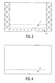
- a caption line shown by ⁇ is displayed in an image region, for example, as shown in Fig. 3.
- a region indicated by X is an image region in which captions are displayed and hereinafter will be referred as a caption region.
- a region indicated by Y is an image region in which captions are inserted and hereinafter will be referred as a caption insertion region. As regards Y, it also will be the same in following figures.
- the 16:9 television is provided with a function for expanding the image to the whole of the screen. But, when this image is merely performed as expanded, the caption line is missed from the screen as shown in Fig. 4.
- a caption moving device for example, as illustrated by a block diagram in Fig. 6 is used in a prior art.
- the operating function will be explained as follows.
- an input image signal from an image input 61 is inputted to an A/D converter 62 and an input terminal 68a of an image/caption changing part 68.
- the A/D converter 62 performs an A/D conversion of the input image signal to generate image information corresponding to this image signal.
- This image information is written into a memory (MEM) 64.
- the memory 64 has a capacity enough to at least store a signal which constructs the caption region, for example, indicated by X in Fig. 3.
- a control signal generating part (CTRL) 65 is connected to the memory 64.
- the control signal generating part 65 generates a control signal used for controlling a writing/reading position of the image information inputted to the memory 64.
- the memory 64 Based on the control signal generated by the control signal generating part 65, the memory 64 begins to write image information at a point of time when the image signal reaches to the caption region X of a certain field, begins to read the stored image information at a point of time when the image signal reaches to the caption insertion region, for example, indicated by Y of a next field and begins to write image information again at a point of time when the image signal reaches to the caption region X of this field. Subsequently, the image information is read from the memory 64 and then inputted to a D/A converter 66 and a caption judging part 67. The D/A converter 66 performs a D/A conversion of the image information to generate an image signal corresponding to this image information. This image signal is inputted to an input terminal 68b of the image/caption changing part 68.
- the image information inputted to the caption judging part 67 is judged whether this information represents a caption or an image. If the inputted image information is judged a caption, for example, a high level control signal is outputted from the caption judging part 67 to the image/caption changing part 68. On the other hand, if the information is judged an image, for example, a low level control signal is outputted therefrom.
- the caption judging part 67 will be explained in detail later.
- the image/caption changing part 68 changes a switch based on the control signal from the caption judging part 67. Namely, if the high level control signal is inputted from the caption judging part 67, the image/caption changing part 68 set the switch to a position 68b-68c. As a result of this, an image signal, which represents a caption, for example, one field before, is outputted from an image signal output 69. Also, if the low level control signal is inputted therefrom, the image/caption changing part 68 set the switch to a position 68a-68c. As a result of this, an image signal, which represents a newest image, is outputted from the output 69. The image signal is displayed on the screen after the expanding process by means of a conventional image expanding device (not shown). Thus, the caption does not miss from the screen (the image region) if the image expanding function which the 16:9 television comprises is performed.
- captions are white (an achromatic color).
- a chroma (color) signal is not included in an image signal which represents white but this image signal consists of only a high level luminance signal.
- the caption judging part 67 is aimed at this point, which is provided with a predetermined reference level for judging whether the inputted image signal represents a caption or not. Namely, the caption judging part 67 judges that only the inputted image information of which a luminance level exceeds the reference level, i.e. only the image information of a high luminance level, represents a caption.
- an image signal S of a telecine as shown in Fig. 7A and B is inputted to the image signal input 61.
- a signal part as indicated by a of the image signal S in Fig. 7 represents captions.
- signal parts of a high luminance level as indicated by b and c in Fig. 7 generally exist in the image signal.
- a broken line R indicates the reference level set to the caption judging part 67. If the caption judgment of the image signal S is performed at this level, not only the caption signal part a but also the high level luminance signal parts b and c representing an image are judged captions. As a result of this, a control signal P shown in Figs.
- an image of a high luminance level is also judged captions in the conventional 16:9 television.
- the screen during expanding is very distinct because such moved image and an image present in the caption insertion region are overlapped.
- a further aspect of the invention is aimed that edging whose color is usually black is applied to a caption of, for example, the telecine and a sharp change of luminance level is occurred between a white (a high luminance) caption and the black (a low luminance) edging as shown Fig. 8.
- Fig. 1 shows a block diagram of an embodiment of a caption moving device according to the invention.
- the reference numeral 1 designates a image signal input, which is connected to a Y/C separating part 2.
- the Y/C separating part 2 is connected to a rate of change detecting part 3 and a first memory (MEMi) 4.
- the rate of change detecting part 3 is connected to a rate of change judging part 5.
- the rate of change judging part 5 is connected to a reference level signal input 6 which inputs a reference signal to judge caption edging, and a gate 7.
- the first memory 4 is connected to the gate 7.
- the gate 7 is connected to a caption judging part 8.
- the caption judging part 8 is connected to a second memory (MEMe) 9.
- the second memory 9 is connected to a control signal generating part (CTRL) 10 which generates a control signal for controlling a writing/reading position of a caption signal inputted to the memory 9.
- CTRL control signal generating part
- An input image signal inputted to the image signal input 1 is inputted to the Y/C separating part 2.
- an Y/C separation corresponding to the input image signal is performed to generate a luminance signal and a chroma signal corresponding to the input image signal.
- Symbol Y represents a luminance
- symbol C represents a color. In this embodiment, only a luminance signal Y corresponding to the input image signal is outputted from the Y/C separating part 2.
- the luminance signal is inputted to the rate of change detecting part 3.
- This rate of change detecting part 3 is a so-called differential circuit (d/dt).
- d/dt differential circuit
- the rate of change of the luminance level of the input luminance signal is detected.
- the larger the value thereof means the larger the change of the luminance level.
- a rate of change signal corresponding to the detected rate of change is generated.
- This rate of change signal is outputted toward the rate of change judging part 5.
- the rate of change judging part 5 is a so-called comparator (COMP1), which judges whether the inputted rate of change signal represents a rate of change more than the certain constant level or not. For this judgment, a reference signal (REF) of a certain level is inputted to the rate of change judging part 5 from the input 6. Then, the rate of change judging part 5 compares the rate of change level of the rate of change signal from the rate of change detecting part 3 with the reference level. When the rate of change level exceeds the reference level, i.e. when the rate of change is larger, for example, a high level control signal which represents valid is generated. On the other hand, when the rate of change level does not exceed the reference level, i.e. when the rate of change is smaller, for example, a low level control signal which represents invalid is generated. This control signal is outputted toward a gate 7.
- COMP1 so-called comparator
- the luminance signal outputted from the Y/C separating part 2 is also written into a first memory 4.
- the inputted luminance signal is stored for a certain period. This certain period is a period is necessary for the rate of change signal generating process of the luminance signal outputted from the Y/C separating part 2 in the rate of change detecting part 3 and for the rate of change judging process of the rate of change signal generated by said process in the rate of change judging part 5.
- the luminance signal is read to output toward the gate 7.
- the gate 7 performs an output control of the luminance signal from the first memory 4 in accordance with the state of the control signal from the rate of change judging part 5. Namely, for example, only if the high level control signal is received from the rate of change judging part 5, the luminance signal from the first memory 4 is outputted.
- the luminance signal outputted from the gate 7 is inputted to the caption judging part 8.
- the caption judging part 8 is a so-called comparator (COMP2), which compares a luminance level of the input luminance signal with a predetermined reference level. Based on this comparison result, this part 8 judges whether the signal represents a caption or an image. Namely, when the luminance level of the input luminance signal exceeds the reference level at the caption judging part 8, this luminance signal is judged to represent a caption and then, for example, a high level caption signal which represents valid is generated. On the other hand, when the input luminance signal doesn't exceed the reference level, this luminance signal is judged to represent an image and then, for example, a low level caption signal which represents invalid is generated. Then, this caption signal is written into the second memory 9. At this point, the caption signal written into the second memory 9 is that it represents only a caption which doesn't include the black edge part applied around the caption and the image part, for example, as shown in Fig. 2.
- the second memory 9 comprises a capacity, for example, enough to at least store the signal which constructs the caption region indicated by X in Fig. 3.
- the control signal generating part 10 which generates a control signal using a writing and reading position control of the inputted caption signal is connected to the memory 9.
- the second memory 9 Based on the control signal generated by the control signal generating part 10, the second memory 9 begins to write a caption signal at a point of time when the image signal reaches to the caption region X of a certain field, begins to read the stored caption signal at a point of time when the image signal reaches to, for example, the caption insertion region indicated by Y of a next field, and begins to write again the caption signal at a point of time when the image signal of this field reaches to the caption region X.
- the caption signal is written into and read from the second memory 9.
- the caption signal read from the second memory 9 is outputted from the caption signal output 11 and then displayed on the screen after performing a conventional insertion process into the image part and a conventional expansion process by an image expanding device (not shown).
- an image signal (a caption signal) which represents an image of a high luminance level is not outputted from the caption signal output 11 but a caption signal which represents only a caption, for example, prior to one field, from which the edge part is removed, is outputted to display together with a newest image signal on the screen.
- the caption moving device of the present invention not only an image signal of a high luminance level is merely judged a caption but also a caption is judged by further detecting a sharp rate of change of an luminance level which occurs between the black edging applied around a caption and this white caption. Therefore, an image part of a high luminance level is not moved into an image region by expanding an image but only a caption is inserted and therefore it is possible to realize a high quality expansion process in a television with an aspect ratio of 16:9.
Landscapes
- Engineering & Computer Science (AREA)
- Multimedia (AREA)
- Signal Processing (AREA)
- Computer Graphics (AREA)
- Studio Circuits (AREA)
- Processing Of Color Television Signals (AREA)
- Controls And Circuits For Display Device (AREA)
Claims (5)
- Titeldetektionsanordnung mit:Mitteln zum Empfangen eines Leuchtdichtesignals entsprechend einem Eingangsbildsignal, das ein Bild darstellt, das ein Titelgebiet aufweist, in dem Titel wiedergegeben werden;Detektionsmitteln zum Detektieren der Änderungsrate eines Leuchtdichtepegels des Leuchtdichtesignal zum Erzeugen eines Änderungsratensignals entsprechend der Änderungsrate;Änderungsratenbeurteilungsmitteln zum Vergleichen eines Änderungsratenpegels des Änderungsratensignals mit einem Pegel eines Bezugssignals, das einzeln eingegeben wird und zum Bewerten eines Inhaltes eines Steuersignals, welches das Vergleichsergebnis darstellt, für gültig, wenn der Änderungsratenpegel den Bezugspegel übersteigt;Gate-Mitteln zum Ausliefern des Leuchtdichtesignals nur dann, wenn das Steuersignal von den Änderungsratenbeurteilungsmitteln einen gültigen Wert darstellen; undTitelbeurteilungsmitteln zum Vergleichen eines Leuchtdichtepegels des Leuchtdichtesignals, das von den Gate-Mitteln ausgeliefert wird mit einem vorbestimmten Bezugspegel und zum Beurteilen eines Inhaltes eines Titelsignals, der das Vergleichsergebnis darstellt, als gültig, wenn das Leuchtdichtesignal den Bezugspegel übersteigt.
- Titeldetektionsanordnung nach Anspruch 1, weiterhin mit den nachfolgenden Elementen:wobei die Auslesesteuerung durchgeführt wird, wenn das Titelsignal entsprechend einem Titeleinfügungsgebiet in das durch das Titelsignal zusammengesetzte Bild erzeugt wird.Speichermitteln zum Speichern des Titelsignals, das von den Titelbeurteilungsmitteln ausgeliefert wird; undSteuersignalerzeugungsmitteln zum Durchführen einer Schreibsteuerung, derart, dass das Titelsignal entsprechend dem Bild des Titelgebietes in die Speichermittel eingeschrieben wird und zum Durchführen einer Auslesesteuerung, derart, dass das Titelsignal aus den Speichermitteln ausgelesen wird;
- Titeldetektionsverfahren, wobei dieses Verfahren die nachfolgenden Verfahrensschritte umfasst:das Empfangen eines Leuchtdichtesignal entsprechend einem Eingangsbildsignal, das ein Bild darstellt, das ein Titelgebiet umfasst, in dem Titel wiedergegeben werden;das Detektieren einer Änderungsrate eines Leuchtdichtepegels eines Leuchtdichtesignals zum Erzeugen eines Änderungsratensignals entsprechend der Änderungsrate;das Vergleichen eines Änderungsratenpegels des Änderungsratensignals mit einem Pegel eines Bezugssignals, das separat eingegeben worden ist und zum Bewerten eines Inhaltes eines Steuersignals, der das Vergleichsergebnis darstellt, als gültig, wenn der Änderungsratenpegel die Bezugspegel übersteigt;das Durchlassen des Leuchtdichtesignals nur dann, wenn das Steuersignal einen gültigen Wert darstellt;das Vergleichen eines Leuchtdichtepegels des durchgelassenen Leuchtdichtesignals mit einem vorbestimmten Bezugspegel und zum Bewerten eines Inhaltes eines Titelsignals, der das Vergleichsergebnis darstellt, als gültig, wenn das durchgelassene Leuchtdichtesignal den bezugspegel übersteigt.
- Titeldetektionsverfahrfen nach Anspruch 3, weiterhin mit den nachfolgenden Verfahrensschritten:wobei die Lesesteuerung durchgeführt wird, wenn das Titelsignal, das einem Titeleinfügegebiet in dem Bild entspricht, das durch das Titelsignal gebildet wird, erzeugt wird.das Speichern des Titelsignals in einem Speichermittel; unddas Durchführen einer Schreibsteuerung, so dass das Titelsignal, das dem Bild des Titelgebietes entspricht, in dem Speichermittel eingeschrieben wird und das Durchführen eine Lesesteuerung, so dass das Titelsignal aus dem Speichermittel ausgelesen wird;
- Videowiedergabeanordnung mit:einer Titeldetektionsanordnung nach Anspruch 1 zum Liefern eines Titelsignals;Mitteln zum Einfügen eines Titels an einer verlagerten Stelle in ein Bild, in Abhängigkeit von dem Titelsignal, zum Erhalten eines Ausgangsbildes, undMitteln zum Wiedergeben des Ausgangsbildes.
Applications Claiming Priority (3)
| Application Number | Priority Date | Filing Date | Title |
|---|---|---|---|
| JP7271702A JPH0993504A (ja) | 1995-09-26 | 1995-09-26 | 字幕移動装置 |
| JP27170295 | 1995-09-26 | ||
| JP271702/95 | 1995-09-26 |
Publications (3)
| Publication Number | Publication Date |
|---|---|
| EP0766461A2 EP0766461A2 (de) | 1997-04-02 |
| EP0766461A3 EP0766461A3 (de) | 1997-06-04 |
| EP0766461B1 true EP0766461B1 (de) | 2000-08-09 |
Family
ID=17503661
Family Applications (1)
| Application Number | Title | Priority Date | Filing Date |
|---|---|---|---|
| EP96202639A Expired - Lifetime EP0766461B1 (de) | 1995-09-26 | 1996-09-20 | Titeldetektion |
Country Status (4)
| Country | Link |
|---|---|
| EP (1) | EP0766461B1 (de) |
| JP (1) | JPH0993504A (de) |
| DE (1) | DE69609684D1 (de) |
| MY (1) | MY132603A (de) |
Families Citing this family (5)
| Publication number | Priority date | Publication date | Assignee | Title |
|---|---|---|---|---|
| US6219382B1 (en) * | 1996-11-25 | 2001-04-17 | Matsushita Electric Industrial Co., Ltd. | Method and apparatus for locating a caption-added frame in a moving picture signal |
| US6366699B1 (en) | 1997-12-04 | 2002-04-02 | Nippon Telegraph And Telephone Corporation | Scheme for extractions and recognitions of telop characters from video data |
| KR100416260B1 (ko) * | 2001-10-19 | 2004-01-24 | 삼성전자주식회사 | 캡션정보 처리장치, 및 캡션텔레비젼 및 캡션처리방법 |
| JP5093557B2 (ja) * | 2006-10-10 | 2012-12-12 | ソニー株式会社 | 画像処理装置、画像処理方法、及びプログラム |
| JP2008167265A (ja) * | 2006-12-28 | 2008-07-17 | Sharp Corp | ディスプレイ構体、テレビジョン装置、及びテレビジョン装置の画面表示方法 |
Family Cites Families (3)
| Publication number | Priority date | Publication date | Assignee | Title |
|---|---|---|---|---|
| JPH0626437B2 (ja) * | 1987-11-12 | 1994-04-06 | シャープ株式会社 | 画像読み取り装置 |
| JP3060475B2 (ja) * | 1990-03-13 | 2000-07-10 | ソニー株式会社 | テレビジョン受像機 |
| GB9312690D0 (en) * | 1993-06-18 | 1993-08-04 | Philips Electronics Uk Ltd | Television receiver |
-
1995
- 1995-09-26 JP JP7271702A patent/JPH0993504A/ja not_active Withdrawn
-
1996
- 1996-09-20 DE DE69609684T patent/DE69609684D1/de not_active Expired - Lifetime
- 1996-09-20 EP EP96202639A patent/EP0766461B1/de not_active Expired - Lifetime
- 1996-09-26 MY MYPI96003985A patent/MY132603A/en unknown
Also Published As
| Publication number | Publication date |
|---|---|
| DE69609684D1 (de) | 2000-09-14 |
| EP0766461A3 (de) | 1997-06-04 |
| EP0766461A2 (de) | 1997-04-02 |
| JPH0993504A (ja) | 1997-04-04 |
| MY132603A (en) | 2007-10-31 |
Similar Documents
| Publication | Publication Date | Title |
|---|---|---|
| CN1126369C (zh) | 提供封闭字幕数据的定格的系统和方法 | |
| US5914719A (en) | Index and storage system for data provided in the vertical blanking interval | |
| KR100196554B1 (ko) | 로고를 갖는 레터박스 신호 처리 시스템 및 방법 | |
| KR100828354B1 (ko) | 자막 위치 제어 장치 및 방법 | |
| US5581304A (en) | Screen detecting system of a wide screen television for detecting blank top and bottom areas | |
| US5680176A (en) | Apparatus for controlling caption display on a wide aspect ratio | |
| EP0766461B1 (de) | Titeldetektion | |
| JP2002351442A (ja) | 映像表示装置における焼付け防止装置 | |
| WO1996038981A2 (en) | Caption moving | |
| JPH09214847A (ja) | 映像信号処理装置 | |
| KR100745299B1 (ko) | 디지털티브이의화면동기장치및방법 | |
| JPH0787392A (ja) | 子画像の表示制御装置 | |
| WO1997008889A1 (en) | Caption moving | |
| JP3164728B2 (ja) | 自動字幕表示装置 | |
| JPH0918802A (ja) | 映像信号処理装置 | |
| JP2692501B2 (ja) | 映像信号の文字位置移動回路 | |
| JPH07143417A (ja) | 映像信号の文字位置移動回路 | |
| JP2734919B2 (ja) | 映像信号の文字位置移動回路 | |
| JP2737601B2 (ja) | 映像信号の文字位置移動回路 | |
| KR19990004721A (ko) | 텔레비전의 캡션문자크기 조정장치 | |
| JPH05199462A (ja) | 映像信号処理回路 | |
| JPH03145878A (ja) | ビデオカメラ | |
| JP3524193B2 (ja) | ワイドアスペクトテレビジョン | |
| JPH05183815A (ja) | 映像信号の文字位置移動回路 | |
| JPH06261260A (ja) | 画像表示装置 |
Legal Events
| Date | Code | Title | Description |
|---|---|---|---|
| PUAI | Public reference made under article 153(3) epc to a published international application that has entered the european phase |
Free format text: ORIGINAL CODE: 0009012 |
|
| AK | Designated contracting states |
Kind code of ref document: A2 Designated state(s): BE DE FR GB NL |
|
| PUAL | Search report despatched |
Free format text: ORIGINAL CODE: 0009013 |
|
| AK | Designated contracting states |
Kind code of ref document: A3 Designated state(s): BE DE FR GB NL |
|
| 17P | Request for examination filed |
Effective date: 19971204 |
|
| GRAG | Despatch of communication of intention to grant |
Free format text: ORIGINAL CODE: EPIDOS AGRA |
|
| 17Q | First examination report despatched |
Effective date: 19991019 |
|
| GRAG | Despatch of communication of intention to grant |
Free format text: ORIGINAL CODE: EPIDOS AGRA |
|
| GRAH | Despatch of communication of intention to grant a patent |
Free format text: ORIGINAL CODE: EPIDOS IGRA |
|
| GRAH | Despatch of communication of intention to grant a patent |
Free format text: ORIGINAL CODE: EPIDOS IGRA |
|
| GRAA | (expected) grant |
Free format text: ORIGINAL CODE: 0009210 |
|
| AK | Designated contracting states |
Kind code of ref document: B1 Designated state(s): BE DE FR GB NL |
|
| PG25 | Lapsed in a contracting state [announced via postgrant information from national office to epo] |
Ref country code: NL Free format text: LAPSE BECAUSE OF FAILURE TO SUBMIT A TRANSLATION OF THE DESCRIPTION OR TO PAY THE FEE WITHIN THE PRESCRIBED TIME-LIMIT Effective date: 20000809 Ref country code: FR Free format text: LAPSE BECAUSE OF FAILURE TO SUBMIT A TRANSLATION OF THE DESCRIPTION OR TO PAY THE FEE WITHIN THE PRESCRIBED TIME-LIMIT Effective date: 20000809 Ref country code: BE Free format text: LAPSE BECAUSE OF FAILURE TO SUBMIT A TRANSLATION OF THE DESCRIPTION OR TO PAY THE FEE WITHIN THE PRESCRIBED TIME-LIMIT Effective date: 20000809 |
|
| REF | Corresponds to: |
Ref document number: 69609684 Country of ref document: DE Date of ref document: 20000914 |
|
| PG25 | Lapsed in a contracting state [announced via postgrant information from national office to epo] |
Ref country code: GB Free format text: LAPSE BECAUSE OF NON-PAYMENT OF DUE FEES Effective date: 20001109 |
|
| PG25 | Lapsed in a contracting state [announced via postgrant information from national office to epo] |
Ref country code: DE Free format text: LAPSE BECAUSE OF FAILURE TO SUBMIT A TRANSLATION OF THE DESCRIPTION OR TO PAY THE FEE WITHIN THE PRESCRIBED TIME-LIMIT Effective date: 20001110 |
|
| NLV1 | Nl: lapsed or annulled due to failure to fulfill the requirements of art. 29p and 29m of the patents act | ||
| EN | Fr: translation not filed | ||
| PLBE | No opposition filed within time limit |
Free format text: ORIGINAL CODE: 0009261 |
|
| STAA | Information on the status of an ep patent application or granted ep patent |
Free format text: STATUS: NO OPPOSITION FILED WITHIN TIME LIMIT |
|
| GBPC | Gb: european patent ceased through non-payment of renewal fee |
Effective date: 20001109 |
|
| 26N | No opposition filed |