EP0766802B1 - Flüssigkeitsregelventil mit dämpfer und dynamischer abdichtung - Google Patents
Flüssigkeitsregelventil mit dämpfer und dynamischer abdichtung Download PDFInfo
- Publication number
- EP0766802B1 EP0766802B1 EP95923085A EP95923085A EP0766802B1 EP 0766802 B1 EP0766802 B1 EP 0766802B1 EP 95923085 A EP95923085 A EP 95923085A EP 95923085 A EP95923085 A EP 95923085A EP 0766802 B1 EP0766802 B1 EP 0766802B1
- Authority
- EP
- European Patent Office
- Prior art keywords
- attenuator
- ball
- annular seal
- fluid
- valve
- Prior art date
- Legal status (The legal status is an assumption and is not a legal conclusion. Google has not performed a legal analysis and makes no representation as to the accuracy of the status listed.)
- Expired - Lifetime
Links
Images


Classifications
-
- F—MECHANICAL ENGINEERING; LIGHTING; HEATING; WEAPONS; BLASTING
- F16—ENGINEERING ELEMENTS AND UNITS; GENERAL MEASURES FOR PRODUCING AND MAINTAINING EFFECTIVE FUNCTIONING OF MACHINES OR INSTALLATIONS; THERMAL INSULATION IN GENERAL
- F16K—VALVES; TAPS; COCKS; ACTUATING-FLOATS; DEVICES FOR VENTING OR AERATING
- F16K47/00—Means in valves for absorbing fluid energy
- F16K47/08—Means in valves for absorbing fluid energy for decreasing pressure or noise level and having a throttling member separate from the closure member, e.g. screens, slots, labyrinths
-
- F—MECHANICAL ENGINEERING; LIGHTING; HEATING; WEAPONS; BLASTING
- F16—ENGINEERING ELEMENTS AND UNITS; GENERAL MEASURES FOR PRODUCING AND MAINTAINING EFFECTIVE FUNCTIONING OF MACHINES OR INSTALLATIONS; THERMAL INSULATION IN GENERAL
- F16K—VALVES; TAPS; COCKS; ACTUATING-FLOATS; DEVICES FOR VENTING OR AERATING
- F16K5/00—Plug valves; Taps or cocks comprising only cut-off apparatus having at least one of the sealing faces shaped as a more or less complete surface of a solid of revolution, the opening and closing movement being predominantly rotary
- F16K5/06—Plug valves; Taps or cocks comprising only cut-off apparatus having at least one of the sealing faces shaped as a more or less complete surface of a solid of revolution, the opening and closing movement being predominantly rotary with plugs having spherical surfaces; Packings therefor
- F16K5/0605—Plug valves; Taps or cocks comprising only cut-off apparatus having at least one of the sealing faces shaped as a more or less complete surface of a solid of revolution, the opening and closing movement being predominantly rotary with plugs having spherical surfaces; Packings therefor with particular plug arrangements, e.g. particular shape or built-in means
Definitions
- This invention relates to fluid control valves and more particularly to such valves with noise attenuators.
- Fluid control valves are often utilized in precisely controlling the amount of fluid applied to a system in response to valve controllers and actuators.
- the precise control of fluid is desired in such systems to control the delivery of a precise amount of fluid, or in order to conserve the application and use of fluid additives which may be extremely dangerous or highly expensive.
- the control valve also must provide a reliable sealing shut-off of the fluid flow when the valve is placed in the shut-off position to prevent the undesired loss of fluid through leakage.
- a noise attenuator must be used in the pipeline system of either single stage or multi-stage attenuation capability so as to reduce the aerodynamic and hydrodynamic noise within the system, and it is desirable to include the noise attenuator within the fluid control valve.
- such fluid control valves utilize a rotating ball control member mounted in a valve body passageway and with suitable sealing provided between the ball and the valve body. Normally, in a shut-off position of the ball control member the ball blocks the flow of fluid through the valve body passageway from an inlet to an outlet by virtue of the ball sealingly engaging a sealing member. The fluid flow is thus stopped by the ball control member and the reliable seal prevents the fluid from otherwise passing between the rotating ball control member and the valve body and undesirably leaking into the valve outlet.
- the ball control member In a typical fluid control member, the ball control member is rotated to the open position in the valve body passageway to enable fluid flow to pass from the valve inlet through the ball and to the valve outlet.
- this condition leads to a high degree of friction between the ball and the seal during ball rotation for controlling fluid flow.
- the high degree of friction resulting from the loading required to obtain a reliable seal during valve shut-off significantly impairs the ability to precisely position the ball control member which in turn determines the exact fluid flow which is desired in many instances.
- An added problem is the need to provide a noise attenuator mounted within the fluid control valve structure.
- US-A-5.070 909 discloses a rotary control valve comprising trim elements located on either side (upstream or downstream) of a rotating ball 29 where the inside face of the slidably mounted trim assembly comprises an annular segment which engages an exterior surface of the ball.
- the reference fails to teach the following: a sealing element per se; an annular seal mounted in the attenuator or spring means coupled to a seal holder within a cavity, also within the attenuator; a spring means adapted to counterbalance the pressure exerted by fluid flow passing an attenuator; and the annular seal means used by the spring means.
- a dynamic sealing configuration for a ball control member of a rotary fluid control valve which includes a noise attenuator device.
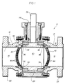
- Figure 1 illustrates a configuration with two attenuators.
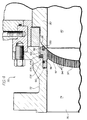
- Figure 2 illustrates a dynamic seal mechanism for a fluid control valve which is particularly useful for bi-directional fluid flow usage.
- Figures 3 and 4 illustrate an alternative dynamic sealing configuration in a uni-directional fluid control valve which features a pressure balanced seal condition providing substantially no friction with the ball during flow control, while enabling a reliable sealing engagement with the ball during valve shut-off.
- a fluid control valve 10 includes valve body end pieces 12 and 13 with a passageway 14 for coupling fluid in either direction between a first valve port 16 and a second valve port 18. Respective mounting flanges 20, 22 are provided for mounting the control valve 10 within a pipeline system.
- a rotatable ball control member 24 includes a rotatable shaft 26 which in turn is mounted within a valve body 28. The ball control member 24 includes a channel 30 extending through the ball control member 24 between opposite surfaces 32, 34.
- each of the noise attenuators 40, 42 is dome-shaped and includes a plurality of apertures 44 forming fluid passageways through the dome-shaped noise attenuators.
- valve body end piece 12 includes a body flange portion 46 which has a stepped cavity section 48.
- the attenuator dome 40 has a perimeter 50 with an outer profile in stepped fashion to match the stepped cavity 48 as shown in Figure 2.
- An O-ring 52 is securely nested within a suitable annular depression in the perimeter 50.
- the noise attenuator dome 40 is installed in the valve body end piece 12 by inserting the perimeter 50 within the stepped cavity 48 and clamping the two pieces together by means of a threaded bolt 51 threadably inserted into the valve body flange 46 and mounted into the valve body 28. This forces a bearing plate 53 securely against the flange portion 46 to rigidly maintain the noise attenuator 40 between the valve body 28 and body end piece 12.
- Sealing of the ball control member 24 is provided by a floating seal configuration floatingly mounted within the attenuator and which includes the seal member 36 dynamically engaging the ball surface 32 of the ball 24.
- Seal member 36 is an annular seal member insertably mounted within an annular seal holder 56 which includes a shoulder 58.
- the seal holder 56 is sized with respect to an annular cavity in the attenuator dome perimeter 50 so it can slidably move within the cavity.
- a spring 60 is trapped between the shoulder 58 on the seal holder 56 and a stop wall 62 of the attenuator dome perimeter 50.
- the spring 60 can be an annular wave spring, and the seal member 36 can be formed of nylon, tetrafluoroethylene, or other elastomer or suitable metal material.
- the spring 60 on the seal holder 56 biases the seal 36 against the ball surface 32 in accordance with the invention, with the valve 10 in the open position where the channel 30 communicates with the input fluid flow from the first port 16.
- the sealing member 36 and the spring 60 are adjusted in size and spring force to enable a minimum of friction between the sealing member 36 and the ball surface 32. This provides the desired precise control operation during normal fluid flow.
- the valve 10 is placed in the shut-off position where the channel 30 no longer communicates with the valve body passageway 14
- the pressure of the blocked fluid flow in the passageway 14 acts on the seal holder 56 so as to cause the seal member 36 to securely engage the ball surface 32 and provide a reliable shut-off condition.
- an O-ring 64 may be used to prevent fluid leakage around the seal holder 56.
- the dynamic seal of Figure 2 can be used in a dual seal configuration as in Figure 1 and may also be used with fluid bleeding to verify dual seal integrity as in a double block and bleed configuration.
- the dynamic seal of Figure 2 also can be used as a single stage attenuator/seal in a fluid control valve.
- FIG. 3 wherein there is illustrated a fluid control valve 70 containing a dynamic seal particularly adaptable for uni-directional flow of fluid and which provides zero or a very small amount of friction with the ball during ball rotation while providing a much more secure sealing engagement during valve shut-off.
- the fluid control valve 70 includes a valve body 72 having a passageway 74 for communicating fluid between an input port 78 and an output port 76.
- a ball control member 80 includes a channel bore 82 and a rotary shaft 84 for placing the valve in an open position with the channel 82 communicating with the passageway 74 or in a shut-off position where the channel 82 no longer communicates with the passageway 74 and the ball surfaces 86, 88 securely engage respective seals in the valve body.
- the seal mechanism includes seal material embedded in the dynamically biased and floating attenuator structure instead of the rigidly clamped attenuator and dynamically biased seal 54 in the seal holder 56 as previously described in connection with Figure 2.
- the valve body 72 includes a stepped cavity portion 90 at the downstream side of the valve, within which there is mounted a noise attenuator 92 having a series of apertures 94.
- a perimeter portion 96 of the attenuator 92 includes an annular groove 98 within which is mounted an annular seal member 100.
- An outer shoulder 102 is provided on the attenuator perimeter 96 so as to accommodate an annular wave spring 104 mounted between the shoulder 102 and a flange stop wall 106 of the valve body.
- An O-ring 108 prevents fluid leakage around the seal.
- a gap seal member formed of an annular resilient sealing material can be utilized to prevent debris from collecting in the seal mechanism cavity and to prevent possible tone generation which would be an undesired noise source.
- a standard spring loaded ball seal 112 is mounted at the upstream side of the valve if double block and bleed sealing is desired.
- the fluid control valves with attenuators described herein can be used to control various fluids, including liquids and gases.
- Attenuator hole diameters of about 0.125 inch (0.318 cm) have been used in prototypes.
- gases the holes through the attenuator would be of small diameter.
- liquids the holes may be of special shape to improve anti-cavitation performance.
- other shapes such as flat could be used for the surface 97 opposite the ball.
- the same valve body is used for both of the embodiments shown in Figures 2 and 4 so as to minimize manufacturing costs and inventory requirements and lead to greater product flexibility.
Landscapes
- Engineering & Computer Science (AREA)
- General Engineering & Computer Science (AREA)
- Mechanical Engineering (AREA)
- Taps Or Cocks (AREA)
- Details Of Valves (AREA)
- Fluid-Driven Valves (AREA)
- Fluid-Damping Devices (AREA)
- Combined Devices Of Dampers And Springs (AREA)
- Magnetically Actuated Valves (AREA)
- Safety Valves (AREA)
Claims (13)
- Kombination aus einem drehbaren Fluidregelventil und einer Lärmdämpfungseinrichtung, wobei die Kombination während der Drehregelung des Fluidflusses in einem Rohrleitungssystem ein zuverlässiges Absperren des Fluidflusses und eine geringe Reibung zur Verfügung stellt, wobei die Kombination folgendes aufweist:dadurch gekennzeichnet, daßeinen Ventilkörper (12, 13, 28), der einen Fluideinlaß (16), einen Fluidauslaß (18) und einen verbindenden Durchgang (14) hat,eine Kugel (24), die in dem Ventilkörper (12, 13) starr angebracht und innerhalb des Durchgangs (14) von einer Ventilabsperrposition in eine Ventiloffenposition drehbar ist, um den Fluidfluß von dem Fluideinlaß (16) zu dem Fluidauslaß (18) zu regeln, undeine erste Dämpfungseinrichtung (40), die in dem Durchgang (14) angrenzend an die Kugel (24) angebracht ist, wobei die erste Dämpfungseinrichtung eine Vielzahl von Öffnungen (44) zum Verringern des Lärms in dem Rohrleitungssystem aufweist,eine erste ringförmige Dichtung (36) in der ersten Dämpfungseinrichtung (40) so angebracht ist, daß sie die Kugel (24) berührt,die erste Dämpfungseinrichtung (40) in dem Durchgang (14) starr angebracht ist und einen Umfangsbereich (50) mit einem ringförmigen Hohlraum aufweist, welcher der Kugel (24) zugewandt ist;ein ringförmiger Dichtungshalter (56) in dem ringförmigen Hohlraum gleitbar angebracht ist, wobei der ringförmige Dichtungshalter (56) eine Einrichtung zum Zurückhalten der ersten ringförmigen Dichtung (36) aufweist; undFedereinrichtungen (60)die mit dem Dichtungshalter (56) gekoppelt sind, um die erste ringförmige Dichtung (36) in Eingriff mit der in der Ventilabsperrposition befindlichen Kugel (24) zu drängen.
- Kombination aus einem drehbaren Fluidregelungsventil und einer Lärmdämpfungseinrichtung nach Anspruch 1 zum Bereitstellen eines bidirektionalen Fluidregelungsventils, wobei die Kombination ferner folgendes aufweist:eine zweite Dämpfungseinrichtung (42), die in dem Durchgang (14) angrenzend an die Kugel und auf der zu der ersten Dämpfungseinrichtung (40) entgegengesetzten Seite starr angebracht ist, wobei die zweite Dämpfungseinrichtung (42) eine Vielzahl von Öffnungen zum Dämpfen des Fluidflusses durch den Durchgang (14) aufweist;eine zweite ringförmige Dichtung (38), die zwischen der zweiten Dämpfungseinrichtung (42) und der Kugel (24) angebracht ist; undeine zweite Federeinrichtung, die mit der zweiten ringförmigen Dichtung (38) gekoppelt ist, um die zweite ringförmige Dichtung (38) in Eingriff mit der in der Ventilabsperrposition befindlichen Kugel (24) zu drängen.
- Kombination aus einem drehbaren Fluidregelungsventil und einer Lärmdämpfungseinrichtung nach Anspruch 1,
wobei der ringförmige Dichtungshalter (56) eine Schulter aufweist, um die Feder (60) in dem ringförmigen Hohlraum zu halten und den ringförmigen Dichtungshalter (56) und die erste ringförmige Dichtung (36) in Richtung zu der Kugel (24) vorzuspannen. - Kombination aus einem drehbaren Fluidregelungsventil und einer Lärmdämpfungseinrichtung nach Anspruch 2,
wobei die zweite Dämpfungseinrichtung (24) in dem Durchgang (14) schwimmend angebracht ist. - Kombination aus einem drehbaren Fluidregelungsventil und einer Lärmdämpfungseinrichtung nach Anspruch 4,
wobei die zweite Dämpfungseinrichtung (42) einen Umfangsbereich mit der zweiten ringförmigen Dichtung aufweist und die zweite ringförmige Dichtung (38) in dem Umfangsbereich zurückgehalten ist. - Kombination aus einem drehbaren Fluidregelungsventil und einer Lärmdämpfungseinrichtung nach Anspruch 5,
wobei die zweiten Federeinrichtungen zwischen dem Umfangsbereich der zweiten Dämpfungseinrichtung und dem Ventilkörper (12, 13) angebracht sind, um die zweite ringförmige Dichtung (38) in Richtung zu der Kugel vorzuspannen. - Kombination aus einem drehbaren Fluidregelungsventil und einer Lärmdämpfungseinrichtung nach Anspruch 6,
wobei der Fluidfluß eine Druckdifferenz über die zweite Dämpfungseinrichtung (42) ermöglicht, um die Vorspannung zu überwinden und die zweite ringförmige Dichtung (38) im wesentlichen von der Kugel (24) zu trennen. - Kombination aus einem drehbaren Fluidregelungsventil und einer Lärmdämpfungseinrichtung,
wobei die Kombination während der Drehregelung des Fluidflusses in einem Rohrleitungssystem ein zuverlässiges Absperren des Fluidflusses und eine geringe Reibung zur Verfügung stellt, wobei die Kombination folgendes aufweist:dadurch gekennzeichnet, daßeinen Ventilkörper (72), der einen Fluideinlaß (78), einen Fluidauslaß (76) und einen verbindenden Durchgang (74) hat,eine Kugel (82), die in dem Ventilkörper (72) starr angebracht und innerhalb des Durchgangs (74) von einer Ventilabsperrposition in eine Ventiloffenposition drehbar ist, um den Fluidfluß von dem Fluideinlaß (78) zu dem Fluidauslaß (76) zu regeln, undeine erste Dämpfungseinrichtung (92), die in dem Durchgang (74) angrenzend an die Kugel (82) angebracht ist, wobei die erste Dämpfungseinrichtung eine Vielzahl von Öffnungen (94) zum Verringern des Lärms in dem Rohrleitungssystem aufweist,eine erste ringförmige Dichtung (100) zwischen der Dämpfungseinrichtung (92) und der Kugel (82) an der Abstromseite des Ventils (70) angebracht ist; unddruckausgeglichene Dichtungseinrichtungen vorgesehen sind, die Fluiddruckeinrichtungen und Federeinrichtungen (104) aufweisen, die mit der ringförmigen Dichtung (100) gekoppelt sind, wobei die Fluiddruckeinrichtung das erste Dichtungselement (100) von der Kugel weg und gegen die Drängkraft der Federeinrichtung (104) vorspannt, wobei die druckausgeglichenen Dichtungseinrichtungen so ausgebildet sind, daß sie die ringförmige Dichtung (100) in festen Dichtungseingriff mit der in der Ventilabsperrposition befindlichen Kugel (82) drängen, während sie die ringförmige Dichtung (100) in im wesentlichen geringeren Eingriff mit der in der Ventiloffenposition befindlichen Kugel (82) drängt, um während der Drehregelung des Fluidflusses zwischen der ringförmigen Dichtung (100) und der Kugel (82) eine geringe Reibung zu bewirken. - Drehbares Fluidregelungs-ventil und Lärmdämpfungseinrichtung nach Anspruch 8,
wobei die abstromseitige Dämpfungseinrichtung (92) in dem Durchgang (74) schwimmend angebracht ist. - Drehbares Fluidregelungsventil und Lärmdämpfungseinrichtung nach Anspruch 9,
wobei die Dämpfungseinrichtung (92) einen Umfangsbereich (96) mit der ringförmigen Dichtung aufweist und die ringförmige Dichtung (100) in dem Umfangsbereich (96) zurückgehalten ist. - Drehbares Fluidregelungsventil und Lärmdämpfungseinrichtung nach Anspruch 10,
wobei die Federeinrichtung (104) zwischen dem Umfangsbereich (96) der Dämpfungseinrichtung und dem Ventilkörper angebracht ist, um die ringförmige Dichtung (100) in Richtung zu der Kugel vorzuspannen. - Drehbares Fluidregelungsventil und Lärmdämpfungseinrichtung nach Anspruch 11,
wobei der Fluidfluß eine Druckdifferenz über die Dämpfungseinrichtung (92) ermöglicht, um die Vorspannung zu überwinden und die ringförmige Dichtung (100) im wesentlichen von der Kugel zu trennen. - Drehbares Fluidregelungsventil und Lärmdämpfungseinrichtung nach Anspruch 8, die folgendes aufweist:eine zweite ringförmige Dichtung (112), die in dem Durchgang (74) angebracht ist und die Kugel (82) an der Aufstromseite gegenüberliegend der ersten ringförmigen Dichtung (100) berührt; undeine zweite Federeinrichtung, die mit der zweiten ringförmigen Dichtung (112) gekoppelt ist, um die zweite ringförmige Dichtung (112) in Eingriff mit der in der Ventilabsperrposition befindlichen Kugel (82) zu drängen.
Applications Claiming Priority (3)
| Application Number | Priority Date | Filing Date | Title |
|---|---|---|---|
| US262914 | 1994-06-21 | ||
| US08/262,914 US5482249A (en) | 1994-06-21 | 1994-06-21 | Fluid control valve with attenuator and dynamic seal |
| PCT/US1995/007724 WO1995035458A1 (en) | 1994-06-21 | 1995-06-15 | Fluid control valve with attenuator and dynamic seal |
Publications (2)
| Publication Number | Publication Date |
|---|---|
| EP0766802A1 EP0766802A1 (de) | 1997-04-09 |
| EP0766802B1 true EP0766802B1 (de) | 1999-09-08 |
Family
ID=22999610
Family Applications (1)
| Application Number | Title | Priority Date | Filing Date |
|---|---|---|---|
| EP95923085A Expired - Lifetime EP0766802B1 (de) | 1994-06-21 | 1995-06-15 | Flüssigkeitsregelventil mit dämpfer und dynamischer abdichtung |
Country Status (15)
| Country | Link |
|---|---|
| US (1) | US5482249A (de) |
| EP (1) | EP0766802B1 (de) |
| JP (1) | JP3793899B2 (de) |
| KR (1) | KR100420154B1 (de) |
| CN (1) | CN1095054C (de) |
| AT (1) | ATE184383T1 (de) |
| AU (1) | AU698198B2 (de) |
| BR (1) | BR9508105A (de) |
| CA (1) | CA2193673C (de) |
| DE (1) | DE69512064T2 (de) |
| ES (1) | ES2138217T3 (de) |
| FI (1) | FI107639B (de) |
| MX (1) | MX9606590A (de) |
| NO (1) | NO309691B1 (de) |
| WO (1) | WO1995035458A1 (de) |
Families Citing this family (50)
| Publication number | Priority date | Publication date | Assignee | Title |
|---|---|---|---|---|
| CA2153238A1 (en) * | 1993-01-04 | 1994-07-21 | John Sharp | Flow control device |
| US5664760A (en) * | 1995-04-06 | 1997-09-09 | United Technologies Corporation | Pressure regulation valve with integrated downstream pressure tap |
| IT1275826B1 (it) * | 1995-10-30 | 1997-10-17 | Nuovo Pignone Spa | Valvola perfezionata per la regolazione e misura di una portata massica di gas |
| US5772178A (en) * | 1995-12-22 | 1998-06-30 | Rotatrol Ag | Rotary noise attenuating valve |
| US6202487B1 (en) | 1996-08-14 | 2001-03-20 | Frank E. Urias | Liquid level detecting device including a container having a first receptacle and a second receptacle |
| US5868378A (en) * | 1997-01-28 | 1999-02-09 | Fisher Controls International, Inc. | Throttling control in a fluid control valve |
| DE10205757B4 (de) * | 2002-02-12 | 2005-04-21 | Siemens Ag | Messrohr für einen Luftmassensensor und Verfahren zu dessen Herstellung |
| US6935371B2 (en) * | 2002-02-22 | 2005-08-30 | Dresser, Inc. | High capacity globe valve |
| US6807986B2 (en) * | 2002-03-22 | 2004-10-26 | Dresser, Inc. | Noise reduction device for fluid flow systems |
| US20040045291A1 (en) * | 2002-09-06 | 2004-03-11 | David Meheen | Flow laminarizing device |
| US7089963B2 (en) * | 2002-11-26 | 2006-08-15 | David Meheen | Flow laminarizing device |
| US7347223B2 (en) * | 2003-07-21 | 2008-03-25 | The Metraflex Company | Pipe flow stabilizer |
| DE20314134U1 (de) * | 2003-09-10 | 2005-01-13 | Voss Automotive Gmbh | Pneumatischer Abblas-Schalldämpfer |
| US20050151107A1 (en) * | 2003-12-29 | 2005-07-14 | Jianchao Shu | Fluid control system and stem joint |
| KR100513381B1 (ko) * | 2003-12-30 | 2005-09-06 | 두산중공업 주식회사 | 다공형 오리피스판이 설치된 배관 |
| US20050205824A1 (en) * | 2004-03-18 | 2005-09-22 | Osborne Charles A | Segmented ball control valve with universal end connections |
| GB0421634D0 (en) * | 2004-09-29 | 2004-10-27 | Microgen Energy Ltd | A splitter valve |
| JP4563770B2 (ja) * | 2004-10-25 | 2010-10-13 | 株式会社山武 | 低騒音回転弁 |
| US7255129B2 (en) | 2005-02-01 | 2007-08-14 | Pentair Water Pool And Spa, Inc. | Valve with elbow joint diverter |
| US7264221B2 (en) * | 2005-09-19 | 2007-09-04 | Yeary & Associates, Inc. | Butterfly valve assembly with improved flow characteristics |
| JP4627242B2 (ja) | 2005-10-18 | 2011-02-09 | 株式会社山武 | 流体制御弁用ディフューザおよび流体制御弁 |
| JP4615463B2 (ja) * | 2006-03-16 | 2011-01-19 | 興国インテック株式会社 | 吸気異音低減装置及びこれを備えた内燃機関、内燃機関の吸気異音低減装置取付構造 |
| US8556226B2 (en) * | 2006-05-15 | 2013-10-15 | Yongsheng Song | Valve with the device enhancing capability of its closure member and related seat ring to resist erosion |
| US7559531B2 (en) * | 2006-11-30 | 2009-07-14 | Tac, Llc | Low torque ball valve with dynamic sealing |
| DK2225484T3 (da) | 2007-12-07 | 2013-08-19 | Mogas Ind Inc | Impedanssæde til kugleventil |
| EP2268951B1 (de) | 2008-04-24 | 2018-07-11 | Cameron International Corporation | Steuerventil |
| US8413684B2 (en) | 2009-09-16 | 2013-04-09 | Schneider Electric Buildings, Llc | Ball valve with anti-rotational pressure plate |
| US20110073789A1 (en) * | 2009-09-28 | 2011-03-31 | Yeary & Associates, Inc. | Butterfly Valve Flow Control Device |
| US8733733B2 (en) | 2010-04-30 | 2014-05-27 | Fisher Controls International Llc | Sleeve seal assembly and rotary valve having sleeve seal assembly |
| US9097364B2 (en) * | 2012-03-27 | 2015-08-04 | Fisher Controls International Llc | Flow straightening seat ring and control valve having flow straightening seat ring |
| BR112014025591A2 (pt) * | 2012-06-05 | 2017-07-04 | Eaton Corp | luva restritora de fluxo, sistema para testar um fluxo de fluído e método para testar o fluxo de fluído |
| CN102758931A (zh) * | 2012-07-18 | 2012-10-31 | 嘉士凯(苏州)阀门配件有限公司 | 一种上装式球阀 |
| US20140209828A1 (en) * | 2013-01-31 | 2014-07-31 | Belimo Holding Ag | Flow characterizing device and ball valve with such a flow characterizing device |
| US10197168B1 (en) * | 2013-05-31 | 2019-02-05 | Technetics Group Llc | Energized spring seal for a floating valve seat |
| US9506432B2 (en) * | 2013-07-09 | 2016-11-29 | Nok Corporation | Sealing device |
| CN105659011B (zh) * | 2013-08-02 | 2017-12-08 | 株式会社开滋 | 铁路车辆用急速排气阀和铁路车辆的配管系统 |
| CN103821962A (zh) * | 2014-03-10 | 2014-05-28 | 重庆海王仪器仪表有限公司 | 一种降噪球阀 |
| KR101545811B1 (ko) * | 2014-03-25 | 2015-08-24 | 안효득 | 와류 방지용 컨트롤 밸브 |
| JP6649272B2 (ja) * | 2014-12-11 | 2020-02-19 | 株式会社キッツ | 回転弁と鉄道車両用急速排気弁 |
| US9885420B2 (en) * | 2015-05-07 | 2018-02-06 | Sri Energy, Inc. | Gate valve |
| US10828610B2 (en) * | 2017-06-30 | 2020-11-10 | Forum Us, Inc. | Mixing assembly |
| US11162613B2 (en) * | 2018-10-26 | 2021-11-02 | Fisher Controls International Llc | Flow conditioner for a valve assembly |
| US11041571B2 (en) * | 2018-12-07 | 2021-06-22 | Fisher Controls International Llc | Retention mechanism for noise attenuation dome in fluid flow control device |
| US11242942B2 (en) * | 2019-06-13 | 2022-02-08 | Fisher Controls International Llc | Valve trim apparatus for use with valves |
| US12398826B2 (en) * | 2020-01-08 | 2025-08-26 | Control Components, Inc. | Three-dimensional tortuous path flow element for ball control valves |
| KR20230069048A (ko) * | 2020-09-16 | 2023-05-18 | 가부시키가이샤 프로테리아루 | 온도 센서, 그리고 그것을 구비하는 질량 유량계 및 질량 유량 제어 장치 |
| US11686404B2 (en) * | 2020-12-11 | 2023-06-27 | Dresser, Llc | Reducing noise in ball valves |
| CN113830273B (zh) * | 2021-10-22 | 2022-08-09 | 重庆前卫科技集团有限公司 | 进水装置及其安装结构 |
| CN117927697B (zh) * | 2024-03-25 | 2024-06-04 | 成都成高阀门股份有限公司 | 一种耐高温耐磨硬密封浮动球球阀 |
| CN120231889A (zh) * | 2025-05-29 | 2025-07-01 | 中国船舶集团有限公司第七一九研究所 | 调节阀、注水系统及船舶 |
Family Cites Families (17)
| Publication number | Priority date | Publication date | Assignee | Title |
|---|---|---|---|---|
| US2698731A (en) * | 1949-06-29 | 1955-01-04 | Gustave J Koehler | Fluid valve |
| US2796230A (en) * | 1951-03-23 | 1957-06-18 | Walworth Co | Valve construction |
| US3068887A (en) * | 1960-08-24 | 1962-12-18 | Grove Marvin Henry | Valve construction having provisions for valve seat access |
| US3630229A (en) * | 1970-04-09 | 1971-12-28 | Us Navy | Quiet fluid flow regulator |
| US3834664A (en) * | 1973-03-05 | 1974-09-10 | Acf Ind Inc | Ball valve structure having pressure actuated seats |
| US4085774A (en) * | 1976-07-19 | 1978-04-25 | Baumann Hans D | Anticavitation and low noise means for rotary valves |
| JPS5825177Y2 (ja) * | 1977-05-30 | 1983-05-30 | 株式会社日本製鋼所 | ボ−ル弁等におけるシ−トリング装置 |
| US4271866A (en) * | 1979-04-02 | 1981-06-09 | The Babcock & Wilcox Company | Drag ball valve including variable pressure reducing means |
| US4295493A (en) * | 1979-04-02 | 1981-10-20 | The Babcock & Wilcox Company | Drag ball valve including variable pressure reducing means |
| US4402485A (en) * | 1981-06-11 | 1983-09-06 | Fisher Controls Company, Inc. | Eccentrically nested tube gas line silencer |
| US4477055A (en) * | 1983-06-30 | 1984-10-16 | Acf Industries, Incorporated | Valve seat for ball valves |
| US4527771A (en) * | 1983-12-07 | 1985-07-09 | Yeary Arthur R | Butterfly valve protector |
| FR2564558B1 (fr) * | 1984-05-18 | 1986-10-03 | Vanatome | Robinet a boisseau tournant spherique |
| US5070909A (en) * | 1990-06-11 | 1991-12-10 | Davenport Robert G | Low recovery rotary control valve |
| US5074522A (en) * | 1991-03-11 | 1991-12-24 | Worcester Controls Corporation | Ball valve having improved inherent rangeability |
| US5180139A (en) * | 1991-10-15 | 1993-01-19 | Fisher Controls International, Inc. | Rotary ball fluid control valve with noise attenuator |
| US5287889A (en) * | 1992-09-22 | 1994-02-22 | Leinen Christopher M | Low-noise rotary control valve |
-
1994
- 1994-06-21 US US08/262,914 patent/US5482249A/en not_active Expired - Lifetime
-
1995
- 1995-06-15 CA CA002193673A patent/CA2193673C/en not_active Expired - Lifetime
- 1995-06-15 ES ES95923085T patent/ES2138217T3/es not_active Expired - Lifetime
- 1995-06-15 KR KR1019960707349A patent/KR100420154B1/ko not_active Expired - Lifetime
- 1995-06-15 WO PCT/US1995/007724 patent/WO1995035458A1/en not_active Ceased
- 1995-06-15 JP JP50252196A patent/JP3793899B2/ja not_active Expired - Fee Related
- 1995-06-15 AT AT95923085T patent/ATE184383T1/de active
- 1995-06-15 BR BR9508105A patent/BR9508105A/pt not_active IP Right Cessation
- 1995-06-15 EP EP95923085A patent/EP0766802B1/de not_active Expired - Lifetime
- 1995-06-15 CN CN95193753A patent/CN1095054C/zh not_active Expired - Lifetime
- 1995-06-15 AU AU27760/95A patent/AU698198B2/en not_active Ceased
- 1995-06-15 DE DE69512064T patent/DE69512064T2/de not_active Expired - Lifetime
- 1995-06-15 MX MX9606590A patent/MX9606590A/es active IP Right Grant
-
1996
- 1996-12-20 NO NO965530A patent/NO309691B1/no not_active IP Right Cessation
- 1996-12-20 FI FI965174A patent/FI107639B/fi not_active IP Right Cessation
Also Published As
| Publication number | Publication date |
|---|---|
| CA2193673C (en) | 2003-10-07 |
| CN1151202A (zh) | 1997-06-04 |
| WO1995035458A1 (en) | 1995-12-28 |
| MX9606590A (es) | 1997-05-31 |
| CA2193673A1 (en) | 1995-12-28 |
| KR100420154B1 (ko) | 2004-06-30 |
| ES2138217T3 (es) | 2000-01-01 |
| FI965174A0 (fi) | 1996-12-20 |
| FI107639B (fi) | 2001-09-14 |
| JP3793899B2 (ja) | 2006-07-05 |
| NO309691B1 (no) | 2001-03-12 |
| FI965174A7 (fi) | 1997-02-17 |
| NO965530D0 (no) | 1996-12-20 |
| DE69512064D1 (de) | 1999-10-14 |
| ATE184383T1 (de) | 1999-09-15 |
| EP0766802A1 (de) | 1997-04-09 |
| CN1095054C (zh) | 2002-11-27 |
| DE69512064T2 (de) | 2000-04-06 |
| NO965530L (no) | 1997-02-20 |
| JPH10504875A (ja) | 1998-05-12 |
| AU2776095A (en) | 1996-01-15 |
| BR9508105A (pt) | 1997-08-12 |
| US5482249A (en) | 1996-01-09 |
| AU698198B2 (en) | 1998-10-29 |
Similar Documents
| Publication | Publication Date | Title |
|---|---|---|
| EP0766802B1 (de) | Flüssigkeitsregelventil mit dämpfer und dynamischer abdichtung | |
| US5501427A (en) | Plate valve | |
| US7712724B2 (en) | Dynamic ball valve sealing device for three-way valves | |
| US5282492A (en) | Dual valve plate two-way pressure relief valve | |
| US4434967A (en) | Valve self-relieving seats | |
| US7559531B2 (en) | Low torque ball valve with dynamic sealing | |
| CA2699221A1 (en) | Metal sealing disk having an elastomeric backing for use with fluid regulators | |
| US9297461B2 (en) | Block and bleed valve assembly | |
| US5152320A (en) | Reverse-acting diverter valve | |
| US20170363217A1 (en) | Main Stage In-Line Pressure Control Cartridge with Optional Reverse Flow Function | |
| US7017608B2 (en) | Balanced globe valve | |
| US20050062006A1 (en) | Valve assembly having a pressure balanced segment seal | |
| US9518670B2 (en) | Main stage in-line pressure control cartridge with stepped retainer collar | |
| GB2259130A (en) | Fluid control valve | |
| CA2989323A1 (en) | Main stage in-line pressure control cartridge with stepped retainer collar | |
| RU2097639C1 (ru) | Отсечной клапан | |
| KR102913519B1 (ko) | 오링프리 체크밸브 | |
| US20050016598A1 (en) | Pressure-operated regulating valve with adjustable deadband | |
| US20250116340A1 (en) | Swing check valve | |
| US4815702A (en) | Gate valve with poppet closure | |
| WO2004085892A1 (en) | An isolation valve assembly |
Legal Events
| Date | Code | Title | Description |
|---|---|---|---|
| PUAI | Public reference made under article 153(3) epc to a published international application that has entered the european phase |
Free format text: ORIGINAL CODE: 0009012 |
|
| 17P | Request for examination filed |
Effective date: 19970116 |
|
| AK | Designated contracting states |
Kind code of ref document: A1 Designated state(s): AT DE ES FR GB IE IT NL SE |
|
| 17Q | First examination report despatched |
Effective date: 19970725 |
|
| GRAG | Despatch of communication of intention to grant |
Free format text: ORIGINAL CODE: EPIDOS AGRA |
|
| GRAG | Despatch of communication of intention to grant |
Free format text: ORIGINAL CODE: EPIDOS AGRA |
|
| GRAH | Despatch of communication of intention to grant a patent |
Free format text: ORIGINAL CODE: EPIDOS IGRA |
|
| GRAH | Despatch of communication of intention to grant a patent |
Free format text: ORIGINAL CODE: EPIDOS IGRA |
|
| GRAA | (expected) grant |
Free format text: ORIGINAL CODE: 0009210 |
|
| AK | Designated contracting states |
Kind code of ref document: B1 Designated state(s): AT DE ES FR GB IE IT NL SE |
|
| REF | Corresponds to: |
Ref document number: 184383 Country of ref document: AT Date of ref document: 19990915 Kind code of ref document: T |
|
| REF | Corresponds to: |
Ref document number: 69512064 Country of ref document: DE Date of ref document: 19991014 |
|
| REG | Reference to a national code |
Ref country code: IE Ref legal event code: FG4D |
|
| ITF | It: translation for a ep patent filed | ||
| ET | Fr: translation filed | ||
| REG | Reference to a national code |
Ref country code: ES Ref legal event code: FG2A Ref document number: 2138217 Country of ref document: ES Kind code of ref document: T3 |
|
| PGFP | Annual fee paid to national office [announced via postgrant information from national office to epo] |
Ref country code: AT Payment date: 20000613 Year of fee payment: 6 |
|
| PGFP | Annual fee paid to national office [announced via postgrant information from national office to epo] |
Ref country code: ES Payment date: 20000623 Year of fee payment: 6 |
|
| PGFP | Annual fee paid to national office [announced via postgrant information from national office to epo] |
Ref country code: IE Payment date: 20000628 Year of fee payment: 6 |
|
| PGFP | Annual fee paid to national office [announced via postgrant information from national office to epo] |
Ref country code: NL Payment date: 20000629 Year of fee payment: 6 |
|
| PLBE | No opposition filed within time limit |
Free format text: ORIGINAL CODE: 0009261 |
|
| STAA | Information on the status of an ep patent application or granted ep patent |
Free format text: STATUS: NO OPPOSITION FILED WITHIN TIME LIMIT |
|
| 26N | No opposition filed | ||
| PG25 | Lapsed in a contracting state [announced via postgrant information from national office to epo] |
Ref country code: IE Free format text: LAPSE BECAUSE OF NON-PAYMENT OF DUE FEES Effective date: 20010615 Ref country code: AT Free format text: LAPSE BECAUSE OF NON-PAYMENT OF DUE FEES Effective date: 20010615 |
|
| PG25 | Lapsed in a contracting state [announced via postgrant information from national office to epo] |
Ref country code: ES Free format text: LAPSE BECAUSE OF NON-PAYMENT OF DUE FEES Effective date: 20010616 |
|
| PG25 | Lapsed in a contracting state [announced via postgrant information from national office to epo] |
Ref country code: NL Free format text: LAPSE BECAUSE OF NON-PAYMENT OF DUE FEES Effective date: 20020101 |
|
| REG | Reference to a national code |
Ref country code: GB Ref legal event code: IF02 |
|
| NLV4 | Nl: lapsed or anulled due to non-payment of the annual fee |
Effective date: 20020101 |
|
| REG | Reference to a national code |
Ref country code: ES Ref legal event code: FD2A Effective date: 20030203 |
|
| REG | Reference to a national code |
Ref country code: FR Ref legal event code: CD Ref country code: FR Ref legal event code: CA |
|
| PG25 | Lapsed in a contracting state [announced via postgrant information from national office to epo] |
Ref country code: IT Free format text: LAPSE BECAUSE OF NON-PAYMENT OF DUE FEES;WARNING: LAPSES OF ITALIAN PATENTS WITH EFFECTIVE DATE BEFORE 2007 MAY HAVE OCCURRED AT ANY TIME BEFORE 2007. THE CORRECT EFFECTIVE DATE MAY BE DIFFERENT FROM THE ONE RECORDED. Effective date: 20050615 |
|
| PGFP | Annual fee paid to national office [announced via postgrant information from national office to epo] |
Ref country code: GB Payment date: 20140627 Year of fee payment: 20 |
|
| PGFP | Annual fee paid to national office [announced via postgrant information from national office to epo] |
Ref country code: DE Payment date: 20140627 Year of fee payment: 20 |
|
| PGFP | Annual fee paid to national office [announced via postgrant information from national office to epo] |
Ref country code: SE Payment date: 20140627 Year of fee payment: 20 Ref country code: FR Payment date: 20140617 Year of fee payment: 20 |
|
| REG | Reference to a national code |
Ref country code: DE Ref legal event code: R071 Ref document number: 69512064 Country of ref document: DE |
|
| REG | Reference to a national code |
Ref country code: GB Ref legal event code: PE20 Expiry date: 20150614 |
|
| PG25 | Lapsed in a contracting state [announced via postgrant information from national office to epo] |
Ref country code: GB Free format text: LAPSE BECAUSE OF EXPIRATION OF PROTECTION Effective date: 20150614 |
|
| REG | Reference to a national code |
Ref country code: SE Ref legal event code: EUG |