EP0766875B1 - Elektrischer verbinder insbesondere für den anschluss einer elektronischen speicherkarte - Google Patents
Elektrischer verbinder insbesondere für den anschluss einer elektronischen speicherkarte Download PDFInfo
- Publication number
- EP0766875B1 EP0766875B1 EP96913606A EP96913606A EP0766875B1 EP 0766875 B1 EP0766875 B1 EP 0766875B1 EP 96913606 A EP96913606 A EP 96913606A EP 96913606 A EP96913606 A EP 96913606A EP 0766875 B1 EP0766875 B1 EP 0766875B1
- Authority
- EP
- European Patent Office
- Prior art keywords
- support
- electrical connector
- plate
- connection part
- parallel
- Prior art date
- Legal status (The legal status is an assumption and is not a legal conclusion. Google has not performed a legal analysis and makes no representation as to the accuracy of the status listed.)
- Expired - Lifetime
Links
Images


Classifications
-
- H—ELECTRICITY
- H01—ELECTRIC ELEMENTS
- H01R—ELECTRICALLY-CONDUCTIVE CONNECTIONS; STRUCTURAL ASSOCIATIONS OF A PLURALITY OF MUTUALLY-INSULATED ELECTRICAL CONNECTING ELEMENTS; COUPLING DEVICES; CURRENT COLLECTORS
- H01R13/00—Details of coupling devices of the kinds covered by groups H01R12/70 or H01R24/00 - H01R33/00
- H01R13/02—Contact members
- H01R13/22—Contacts for co-operating by abutting
- H01R13/24—Contacts for co-operating by abutting resilient; resiliently-mounted
- H01R13/2442—Contacts for co-operating by abutting resilient; resiliently-mounted with a single cantilevered beam
-
- G—PHYSICS
- G06—COMPUTING OR CALCULATING; COUNTING
- G06K—GRAPHICAL DATA READING; PRESENTATION OF DATA; RECORD CARRIERS; HANDLING RECORD CARRIERS
- G06K7/00—Methods or arrangements for sensing record carriers, e.g. for reading patterns
- G06K7/0013—Methods or arrangements for sensing record carriers, e.g. for reading patterns by galvanic contacts, e.g. card connectors for ISO-7816 compliant smart cards or memory cards, e.g. SD card readers
- G06K7/0021—Methods or arrangements for sensing record carriers, e.g. for reading patterns by galvanic contacts, e.g. card connectors for ISO-7816 compliant smart cards or memory cards, e.g. SD card readers for reading/sensing record carriers having surface contacts
-
- H—ELECTRICITY
- H01—ELECTRIC ELEMENTS
- H01R—ELECTRICALLY-CONDUCTIVE CONNECTIONS; STRUCTURAL ASSOCIATIONS OF A PLURALITY OF MUTUALLY-INSULATED ELECTRICAL CONNECTING ELEMENTS; COUPLING DEVICES; CURRENT COLLECTORS
- H01R13/00—Details of coupling devices of the kinds covered by groups H01R12/70 or H01R24/00 - H01R33/00
- H01R13/40—Securing contact members in or to a base or case; Insulating of contact members
- H01R13/405—Securing in non-demountable manner, e.g. moulding, riveting
- H01R13/41—Securing in non-demountable manner, e.g. moulding, riveting by frictional grip in grommet, panel or base
-
- H—ELECTRICITY
- H01—ELECTRIC ELEMENTS
- H01R—ELECTRICALLY-CONDUCTIVE CONNECTIONS; STRUCTURAL ASSOCIATIONS OF A PLURALITY OF MUTUALLY-INSULATED ELECTRICAL CONNECTING ELEMENTS; COUPLING DEVICES; CURRENT COLLECTORS
- H01R13/00—Details of coupling devices of the kinds covered by groups H01R12/70 or H01R24/00 - H01R33/00
- H01R13/62—Means for facilitating engagement or disengagement of coupling parts or for holding them in engagement
- H01R13/629—Additional means for facilitating engagement or disengagement of coupling parts, e.g. aligning or guiding means, levers, gas pressure electrical locking indicators, manufacturing tolerances
-
- H—ELECTRICITY
- H01—ELECTRIC ELEMENTS
- H01R—ELECTRICALLY-CONDUCTIVE CONNECTIONS; STRUCTURAL ASSOCIATIONS OF A PLURALITY OF MUTUALLY-INSULATED ELECTRICAL CONNECTING ELEMENTS; COUPLING DEVICES; CURRENT COLLECTORS
- H01R2201/00—Connectors or connections adapted for particular applications
- H01R2201/16—Connectors or connections adapted for particular applications for telephony
Definitions
- the present invention relates to an electrical connector, especially for the connection of a circuit board (s) integrated contact (s), also called memory card electronic, having on one of its main faces a plurality of electrical contact pads aligned in parallel to the direction of introduction of the card in a read-write device.
- a circuit board (s) integrated contact (s) also called memory card electronic
- the invention relates more particularly to a connector of the type comprising a support of insulating material produced by molding having a flat contact face, parallel to the card insertion direction, and a plurality of parallel electrical conductors in the form of blades elastically deformable which extend longitudinally, parallel to the direction of introduction of the card, and of which each includes a first curved contact end with one of the ranges of the map projecting out of the plane of the flat contact face of the support, a middle portion of connection of the blade to the support and a second end of blade connection, for example to a circuit processing of the read-write device, of the type in which the middle connecting part of each blade has means for fixing the blade to the support which consist by a harpoon-shaped side hooking tab which extends parallel to the middle connecting part, along of a first longitudinal edge thereof, and which is received in a corresponding slot in the support.
- the object of the present invention is to provide a improvement of the design of an electrical connector of the type mentioned above which remedies this disadvantage.
- each contact blade has a lateral stabilization tab which extends along the second longitudinal edge of the middle connecting part, with a slit separating it from this longitudinal edge, and which bears against at least one stabilization surface facing the support parallel to the plane of the flat contact face.
- the invention also provides an electrical connector for the connection of an electronic memory card comprising on one of its main faces a plurality of electrical contact pads aligned parallel to the direction of insertion of the card into a device read-write, characterized in that it is carried out in accordance to the teachings of the claims.
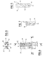
- the support 12 essentially consists of a plate molded plastic material delimited by a flat face of contact 20, by a parallel flat support face 22 and by a wall or side face 18 of substantially contour rectangular.
- the support 12 has a general design symmetry with respect to a plane horizontal P (considering Figures 1 and 3).
- the support 12 On either side of the plane P, the support 12 has two series of four notches 24 aligned two by two.
- Each notch 24 is in the form of a notch with edges or faces 26 which are parallel to direction I to insert or extract a memory card electronics in a read-write device (not shown) equipped with an electrical connector conforming to teachings of the invention.
- the underside 22 is not supported because the connector can be embedded in a card slot.
- each notch 24 extends longitudinally in direction I by a groove 28 which opens into one of the two edges opposite transverse 30 of the support 12.
- the support 12 On either side of each of the eight grooves 28, the support 12 has a slot 32 for hooking a conductor 14 and a slot 34 for stabilizing the conductor.
- the fixing 32 and stabilization 34 slots are made in the thickness of the insulating body 12 and they open longitudinally into a transverse edge 30.
- the longitudinal hooking slot 32 is delimited by two parallel and opposite surfaces 36 and by two edges longitudinal 38.
- the longitudinal stabilization slot 34 is delimited by two parallel stabilization surfaces 40 and by two longitudinal edges 42.
- each slot hook 32 extends longitudinally over a length significantly higher than that of the stabilization slots 34.
- Each conductive element 14 is produced in the form a contact blade made by cutting, folding and bending in a sheet of conductive material.
- Each blade 14 is constituted by a branch main longitudinal which constitutes the middle part of link 42 between a curved and curved free end of contact 44 and a free folded connection end 46.
- the free contact end 44 is intended to be received in a notch 24 of so that its convex rounded portion 48 protrudes beyond of the flat contact face 20 when the conductor 14 is in the position mounted in the insulating support 12.
- the free connection end 46 is bent at 90 ° by relation to the general plan in which the branch extends main 42 so as to extend along the edge transverse 30 of the insulating support and so that its free end section 50 can for example, in this mode to be welded on a conductive track of the card with printed circuit.
- Free connection ends 46 can of course also be of the straight type (mentioned previously) or of the type to be stuck.
- each blade or conductor 14 has a lateral hooking tab 52 in harpoon shape that extends longitudinally along a first longitudinal edge 54 of the main connecting branch 42 and which is intended to be received in a slot attachment 32, by introduction in direction I.
- each blade or conductor 14 has a side tab of stabilization 58 which extends longitudinally along the second longitudinal edge 56 of the main branch 42.
- the lateral hooking 52 and stabilization tabs 58 are connected to the longitudinal edges 54 and 56 by a crosses 60, 62 respectively.
- the stabilization tab 58 is intended to be received, by introduction in direction I, in a slot of stabilization 34.
- the side leg of stabilization is also achieved in the form a harpoon to improve the attachment of the driver 14.
- Face 64 of the central median connecting branch 42 is, in the mounted position of the conductor 14, opposite the bottom of groove 28 in which a groove is formed longitudinal center 66 whose transverse width L3 is less than the width L2 of the groove 28.
- the blade contact 14 is perfectly maintained in a plane parallel to the general plane of the support 12 in which it is recessed in the vicinity of the connection area of the main central connecting branch 42 with the sleepers 60 and 62 thus ensuring very good stability of each blade 14.
- these main branches 42 which are deformed elastically, in a general direction perpendicular to the plane of the contact face 20, without it appearing parasitic tilting movements of the blades 14 around of a substantially longitudinal axis.
- Face 64 of the central median connecting branch 42 is, in the mounted position of the conductor 14, opposite the bottom of groove 28 in which a groove is formed longitudinal center 66 whose transverse width L3 is less than the width L2 of the groove 28.
- the groove 66 allows, during the insertion of the conductor 14 during which the end 44 is received in sliding in groove 66, to limit the deflection of the part elastically deformable and thus avoid deformation permanently detrimental to the subsequent operation of the connector.
- each blade 14 has a enlarged portion 66 whose transverse width L1 is slightly greater than the width L3 of the groove 66 and less than the width L2 of the groove 28, the enlarged portion being resting at rest on the edges 67 of the groove 66.
- each blade 14 can be completed by a formed spout at the free end of the connection end.
- the design of the stabilization means according to the invention allows, while ensuring greater reliability and higher quality of electrical contacts when the introduction of the card, to realize connectors of a very reduced thickness insofar as they do not comprise more additional covers of the insulating support 12 for secure the contact blades 14.
Landscapes
- Engineering & Computer Science (AREA)
- Artificial Intelligence (AREA)
- Computer Vision & Pattern Recognition (AREA)
- Physics & Mathematics (AREA)
- General Physics & Mathematics (AREA)
- Theoretical Computer Science (AREA)
- Coupling Device And Connection With Printed Circuit (AREA)
- Connector Housings Or Holding Contact Members (AREA)
Claims (10)
- Elektrischer Verbinder vom Typ mit einem durch Abformung realisierten Träger (12) aus isolierendem Material, der eine ebene Kontaktfläche (20) und eine Mehrzahl von parallelen elektrischen Leitern (14) in Form von elastisch verformbaren Lamellen aufweist, die sich longitudinal erstrecken und von denen jede ein erstes gekrümmtes Kontaktende (44), das über die Ebene der ebenen Kontaktfläche (20) des Trägers (12) vorspringt, einen mittleren Abschnitt (42) zur Verbindung der Lamelle (14) mit dem Träger (12) und ein zweites Ende (46) zum Anschluß der Lamelle (14) aufweist, von dem Typ, bei dem der mittlere Verbindungsabschnitt (42) jeder Lamelle (14) Mittel (52) zum Befestigen der Lamelle (14) am Träger (12) aufweist, die gebildet sind durch einen seitlichen Einhakfuß (52) in Widerhakenform, der sich parallel zum mittleren Verbindungsabschnitt (42) entlang eines ersten Längsrandes (54) von diesem (42)mit einem ihn von diesem Längsrand trennenden Schlitz erstreckt und der in einem entsprechenden Schlitz (32) des Trägers (12) aufgenommen ist, dadurch gekennzeichnet, daß jede Kontaktlamelle (14) einen seitlichen Stabilisierungsfuß (58) aufweist, der sich entlang des zweiten Längsrandes (56) des mittleren Verbindungsabschnitts (42) erstreckt, mit einem Schlitz, der ihn von diesem Längsrand trennt, und der an wenigstens einer gegenüberliegenden Stabilisierungsoberfläche (40) des zur Ebene der ebenen Kontaktfläche (20) parallelen Trägers (12) anliegt.
- Elektrischer Verbinder nach Anspruch 1, dadurch gekennzeichnet, daß sich der seitliche Stabilisierungsfuß (58) parallel zum mittleren Verbindungsabschnitt (42) erstreckt.
- Elektrischer Verbinder nach Anspruch 2, dadurch gekennzeichnet, daß der seitliche Stabilisierungsfuß (58) in einem entsprechenden Schlitz (34) des Trägers (12) aufgenommen ist, der durch zwei parallele Stabilisierungsoberflächen (40) begrenzt ist.
- Elektrischer Verbinder nach einem beliebigen der Ansprüche 1 bis 3, dadurch gekennzeichnet, daß der seitliche Einhakfuß (52) und der seitliche Stabilisierungsfuß (58) jeweils mit dem benachbarten Längsrand (54, 56) des mittleren Verbindungsabschnitts (42) über einen Querträger (60, 62) verbunden sind, und daß die zwei Querträger (60, 62) in Querrichtung ausgerichtet sind.
- Elektrischer Verbinder nach einem beliebigen der vorhergehenden Ansprüche, dadurch gekennzeichnet, daß der mittlere Verbindungsabschnitt (42) einen Ast (42) umfaßt, dessen freies Ende durch das Anschlußende (46) der Lamelle (14) verlängert ist.
- Elektrischer Verbinder nach Anspruch 5, dadurch gekennzeichnet, daß der Ast (42) des mittleren Verbindungsabschnitts sich einer Rille (28) zugewandt erstreckt, die gegenüberliegend in einer ebenen, zur Ebene der ebenen Kontaktfläche (20) parallelen Fläche (22) des Trägers (12) gebildet ist, um ein Biegen des Astes (42) in einer zu der ebenen Kontaktfläche (20) des Trägers (12) im wesentlichen senkrechten Richtung zu ermöglichen.
- Elektrischer Verbinder nach Anspruch 6, dadurch gekennzeichnet, daß die Rille (28), der gegenüber sich der Ast (42) des mittleren Verbindungsabschnitts erstreckt, in einer ebenen und der ebenen Kontaktfläche (20) entgegengesetzten Auflagefläche (22) des Trägers (12) gebildet ist, und daß der Träger (12) für jede Lamelle (14) eine longitudinale Kerbe (24) umfaßt, die die Rille verlängert und durch die das gekrümmte Kontaktende (44, 48) aus der Ebene der ebenen Kontaktfläche (20) vorsteht.
- Elektrischer Verbinder nach Anspruch 7, dadurch gekennzeichnet, daß das gekrümmte Kontaktende (44) jeder Lamelle (14) mit dem mittleren Verbindungsabschnitt (42) über eine verbreiterte Zone (66) verbunden ist, deren transversale Breite (L1) größer ist als die Breite (L3) einer Nut, die am Boden der Rille (28) gebildet ist, und die kleiner ist als die Breite (L2) der Rille (28).
- Elektrischer Verbinder nach einem beliebigen der vorhergehenden Ansprüche, dadurch gekennzeichnet, daß das Anschlußende (46) jeder Lamelle (14) sich in einer Richtung senkrecht zur Ebene der ebenen Kontaktfläche (20) des Trägers (12) und fort von dem Ast (42) des mittleren Verbindungsabschnitts der Lamelle (14) und entlang eines der Seitenränder (30) des Trägers (12) erstreckt.
- Elektrischer Verbinder zum Anschließen einer elektronischen Speicherkarte, die an einer ihrer Hauptflächen eine Mehrzahl von parallel zur Einführungsrichtung (I) der Karte in eine Schreib-Lesevorrichtung ausgerichteten elektrischen Kontaktfeldern aufweist, dadurch gekennzeichnet, daß er nach einem beliebigen der vorhergehenden Ansprüche ausgebildet ist.
Applications Claiming Priority (3)
| Application Number | Priority Date | Filing Date | Title |
|---|---|---|---|
| FR9504783A FR2733358B1 (fr) | 1995-04-21 | 1995-04-21 | Connecteur electrique, notamment pour le raccordement d'une carte a memoire electronique |
| FR9504783 | 1995-04-21 | ||
| PCT/FR1996/000589 WO1996033527A1 (fr) | 1995-04-21 | 1996-04-18 | Connecteur electrique, notamment pour le raccordement d'une carte a memoire electronique |
Publications (2)
| Publication Number | Publication Date |
|---|---|
| EP0766875A1 EP0766875A1 (de) | 1997-04-09 |
| EP0766875B1 true EP0766875B1 (de) | 2000-06-28 |
Family
ID=9478330
Family Applications (1)
| Application Number | Title | Priority Date | Filing Date |
|---|---|---|---|
| EP96913606A Expired - Lifetime EP0766875B1 (de) | 1995-04-21 | 1996-04-18 | Elektrischer verbinder insbesondere für den anschluss einer elektronischen speicherkarte |
Country Status (7)
| Country | Link |
|---|---|
| US (1) | US5882230A (de) |
| EP (1) | EP0766875B1 (de) |
| JP (1) | JPH10501922A (de) |
| KR (1) | KR970704255A (de) |
| DE (1) | DE69609030T2 (de) |
| FR (1) | FR2733358B1 (de) |
| WO (1) | WO1996033527A1 (de) |
Families Citing this family (19)
| Publication number | Priority date | Publication date | Assignee | Title |
|---|---|---|---|---|
| FR2771834B1 (fr) * | 1997-12-03 | 2000-01-21 | Socapex Amphenol | Dispositif de connexion electrique pour cooperer avec un support electronique mobile |
| FR2773275B1 (fr) * | 1997-12-26 | 2000-01-28 | Itt Mfg Enterprises Inc | Connecteur electrique de tres faible epaisseur pour le raccordement d'une carte a memoire electronique |
| JP3295715B2 (ja) * | 1997-12-26 | 2002-06-24 | 日本圧着端子製造株式会社 | プリント配線板用コネクタ及びその製造方法 |
| US6071152A (en) * | 1998-04-22 | 2000-06-06 | Molex Incorporated | Electrical connector with inserted terminals |
| DE19825808B4 (de) * | 1998-06-09 | 2006-10-26 | Amphenol-Tuchel Electronics Gmbh | Kontaktelement für Chipkartenkontaktiereinrichtung |
| FR2783947B1 (fr) * | 1998-09-29 | 2003-05-23 | Framatome Connectors Int | Connecteur pour lecteur de carte a microcircuit notamment pour carte de petit format |
| FR2787245B1 (fr) * | 1998-12-10 | 2001-02-23 | Framatome Connectors Int | Connecteur a contacts precontraints et son utilisation |
| US6050857A (en) * | 1998-12-22 | 2000-04-18 | Hon Hai Precision Ind. Co., Ltd. | SIM connector and related contact |
| FR2790874B1 (fr) * | 1999-03-11 | 2001-05-04 | Cit Alcatel | Connecteur de faible epaisseur monte en surface sur un circuit imprime |
| US6162102A (en) * | 1999-03-22 | 2000-12-19 | Hon Hai Precision Ind. Co., Ltd. | Contact arrangement for use with high speed transmission |
| US6508673B2 (en) | 2000-04-05 | 2003-01-21 | Mcdowell Jennifer Lyn | Low cost smart card reader, extension style, with wiping contacts |
| JP3595939B2 (ja) * | 2002-03-29 | 2004-12-02 | 日本航空電子工業株式会社 | コネクタ |
| USD494140S1 (en) | 2002-07-05 | 2004-08-10 | San-Yiou Lin | Subscriber identification module |
| USD491893S1 (en) | 2002-11-12 | 2004-06-22 | Advanced Connectek, Inc. | SIM card connector |
| TW570349U (en) * | 2003-04-04 | 2004-01-01 | P Two Ind Inc | Structure of conducting terminal |
| US7909657B1 (en) | 2009-11-12 | 2011-03-22 | Hubbell Incorporated | Electrical connector with low-stress, reduced-electrical-length contacts |
| FR2968466B1 (fr) | 2010-12-07 | 2013-10-25 | Injection Haute Prec | Contact et connecteur de carte a microcircuit |
| US9590331B2 (en) * | 2014-10-28 | 2017-03-07 | Kabushiki Kaisha Toshiba | Card connector |
| DE102021116787B3 (de) * | 2021-06-30 | 2022-11-24 | Lisa Dräxlmaier GmbH | Spannungsabgriff zum messen einer spannung |
Citations (1)
| Publication number | Priority date | Publication date | Assignee | Title |
|---|---|---|---|---|
| EP0803835A2 (de) * | 1993-12-24 | 1997-10-29 | Itt Composants Et Instruments | Raumsparender elektrischer Verbinder für eine IC-Speicherkarte |
Family Cites Families (6)
| Publication number | Priority date | Publication date | Assignee | Title |
|---|---|---|---|---|
| US2099555A (en) * | 1929-10-12 | 1937-11-16 | Monowatt Electric Corp | Electrical connecter |
| US3444504A (en) * | 1967-01-19 | 1969-05-13 | Amp Inc | Electrical connector having stabilizing means and free-floating contact section |
| EP0472692B2 (de) * | 1990-03-17 | 2000-08-23 | AMPHENOL-TUCHEL ELECTRONICS GmbH | Kontaktiereinrichtung, insbesondere für ein sim |
| DE4118312C2 (de) * | 1991-06-04 | 1995-03-09 | Amphenol Tuchel Elect | Kontaktsatz für eine Kontaktzonen aufweisende Karte |
| JP2761489B2 (ja) * | 1992-04-06 | 1998-06-04 | モレックス インコーポレーテッド | 電気コネクタ |
| US5249988A (en) * | 1992-06-04 | 1993-10-05 | Foxconn International, Inc. | Connector and contact therein having enhanced retention and high flexibility |
-
1995
- 1995-04-21 FR FR9504783A patent/FR2733358B1/fr not_active Expired - Fee Related
-
1996
- 1996-04-18 KR KR1019960707286A patent/KR970704255A/ko not_active Ceased
- 1996-04-18 DE DE69609030T patent/DE69609030T2/de not_active Expired - Lifetime
- 1996-04-18 JP JP8531521A patent/JPH10501922A/ja active Pending
- 1996-04-18 WO PCT/FR1996/000589 patent/WO1996033527A1/fr not_active Ceased
- 1996-04-18 EP EP96913606A patent/EP0766875B1/de not_active Expired - Lifetime
- 1996-12-10 US US08/763,330 patent/US5882230A/en not_active Expired - Fee Related
Patent Citations (1)
| Publication number | Priority date | Publication date | Assignee | Title |
|---|---|---|---|---|
| EP0803835A2 (de) * | 1993-12-24 | 1997-10-29 | Itt Composants Et Instruments | Raumsparender elektrischer Verbinder für eine IC-Speicherkarte |
Also Published As
| Publication number | Publication date |
|---|---|
| DE69609030D1 (de) | 2000-08-03 |
| FR2733358A1 (fr) | 1996-10-25 |
| EP0766875A1 (de) | 1997-04-09 |
| DE69609030T2 (de) | 2000-11-02 |
| JPH10501922A (ja) | 1998-02-17 |
| US5882230A (en) | 1999-03-16 |
| WO1996033527A1 (fr) | 1996-10-24 |
| FR2733358B1 (fr) | 1997-05-30 |
| KR970704255A (ko) | 1997-08-09 |
Similar Documents
| Publication | Publication Date | Title |
|---|---|---|
| EP0686289B1 (de) | Elektrischer verbinder zum verbinden von einer elektronischen speicherkarte | |
| WO1996033527A1 (fr) | Connecteur electrique, notamment pour le raccordement d'une carte a memoire electronique | |
| EP1193802B1 (de) | Federsteckverbinder zur Verbindung einer Leiterplatte mit einem Bildschirm | |
| EP0366513B1 (de) | Elektrischer Verbinder für elektronische Gedächtniskarten, Verfahren der Verwirklichung eines derartigen Verbinders und Lese-Schreibvorrichtung mit diesem Verbinder | |
| FR2809871A1 (fr) | Connecteur electrique a lames de contact perfectionnees pour le raccordement d'une carte a circuit(s) integre(s) | |
| EP0860904B1 (de) | Verbinder für IC-Karte und damit ausgerüstetes Gehäuse | |
| EP0756242B1 (de) | Anordnung zur Verbindung einer Chipkarte mit Kontakten in einer Lese- und Schreibvorrichtung und zugehörige Kappe | |
| EP0756355A1 (de) | Elektrischer Steckverbinder zur Verbindung mit den Kontakten einer integrierten gedruckten Schaltung | |
| FR2793353A1 (fr) | Connecteur electrique monobloc pour le raccordement d'une carte a circuit(s) integre(s) | |
| EP0738429B1 (de) | Elektrischer verbinder für eine elektronische speicherkarte mit elektrischen isolationverdrängungsverbindern | |
| FR2821988A1 (fr) | Connecteur electrique pour cartes a memoire electronique a grande capacite de stockage | |
| FR2783622A1 (fr) | Connecteur electrique pour le raccordement simultane de deux cartes a memoire electronique | |
| FR2742561A1 (fr) | Connecteur electrique pour une carte a circuit(s) integre(s) a contact | |
| FR2773275A1 (fr) | Connecteur electrique de tres faible epaisseur pour le raccordement d'une carte a memoire electronique | |
| EP0145542B1 (de) | Verbinder mit kräftefreier Einfügung für einen rechteckigen Chipträger und Anschliessklemme für einen solchen Verbinder | |
| FR2803110A1 (fr) | Connecteur pour carte a microcircuit et procede de montage d'une telle carte dans ce connecteur | |
| EP0711438B1 (de) | Elektrischer verbinder zum verbinden einer elektronischen speicherkarte, mit einem integrierten schalter, der die anwesenheit einer karte erkennt | |
| WO2004066450A1 (fr) | Connecteur a fiches munis de bornes de contact a compression | |
| EP0738983B1 (de) | Elektrischer Verbinder für eine Kontaktkarte mit integrierten Schaltungen | |
| FR2773246A1 (fr) | Commutateur electrique miniaturise, integre a un connecteur, pour la detection de la presence d'une carte a memoire electronique | |
| EP0711440B1 (de) | Elektrische kontakteinheit zum kontaktieren einer elektronischen speicherkarte | |
| EP0656597B1 (de) | Kartenkontaktrahmen und -verbinder | |
| EP0560648B1 (de) | Polygonal Steckverbinder, insbesondere viereckig mit einem isolierenden Zentralkörper | |
| EP0086714A1 (de) | Verbinder für gedruckte Schaltungen | |
| EP1019864A1 (de) | Kartenlesersverbindung mit elektrischen bürstenkontakten und damit ausgerüstete leser |
Legal Events
| Date | Code | Title | Description |
|---|---|---|---|
| PUAI | Public reference made under article 153(3) epc to a published international application that has entered the european phase |
Free format text: ORIGINAL CODE: 0009012 |
|
| 17P | Request for examination filed |
Effective date: 19961210 |
|
| AK | Designated contracting states |
Kind code of ref document: A1 Designated state(s): DE FI FR GB IT NL SE |
|
| 17Q | First examination report despatched |
Effective date: 19980526 |
|
| GRAG | Despatch of communication of intention to grant |
Free format text: ORIGINAL CODE: EPIDOS AGRA |
|
| GRAG | Despatch of communication of intention to grant |
Free format text: ORIGINAL CODE: EPIDOS AGRA |
|
| GRAH | Despatch of communication of intention to grant a patent |
Free format text: ORIGINAL CODE: EPIDOS IGRA |
|
| GRAH | Despatch of communication of intention to grant a patent |
Free format text: ORIGINAL CODE: EPIDOS IGRA |
|
| GRAA | (expected) grant |
Free format text: ORIGINAL CODE: 0009210 |
|
| AK | Designated contracting states |
Kind code of ref document: B1 Designated state(s): DE FI FR GB IT NL SE |
|
| GBT | Gb: translation of ep patent filed (gb section 77(6)(a)/1977) |
Effective date: 20000628 |
|
| REF | Corresponds to: |
Ref document number: 69609030 Country of ref document: DE Date of ref document: 20000803 |
|
| ITF | It: translation for a ep patent filed | ||
| PLBE | No opposition filed within time limit |
Free format text: ORIGINAL CODE: 0009261 |
|
| STAA | Information on the status of an ep patent application or granted ep patent |
Free format text: STATUS: NO OPPOSITION FILED WITHIN TIME LIMIT |
|
| 26N | No opposition filed | ||
| REG | Reference to a national code |
Ref country code: GB Ref legal event code: IF02 |
|
| PGFP | Annual fee paid to national office [announced via postgrant information from national office to epo] |
Ref country code: NL Payment date: 20050329 Year of fee payment: 10 |
|
| PGFP | Annual fee paid to national office [announced via postgrant information from national office to epo] |
Ref country code: GB Payment date: 20050413 Year of fee payment: 10 |
|
| PGFP | Annual fee paid to national office [announced via postgrant information from national office to epo] |
Ref country code: SE Payment date: 20050420 Year of fee payment: 10 |
|
| PG25 | Lapsed in a contracting state [announced via postgrant information from national office to epo] |
Ref country code: GB Free format text: LAPSE BECAUSE OF NON-PAYMENT OF DUE FEES Effective date: 20060418 |
|
| PG25 | Lapsed in a contracting state [announced via postgrant information from national office to epo] |
Ref country code: SE Free format text: LAPSE BECAUSE OF NON-PAYMENT OF DUE FEES Effective date: 20060419 |
|
| PGFP | Annual fee paid to national office [announced via postgrant information from national office to epo] |
Ref country code: IT Payment date: 20060430 Year of fee payment: 11 |
|
| PG25 | Lapsed in a contracting state [announced via postgrant information from national office to epo] |
Ref country code: NL Free format text: LAPSE BECAUSE OF NON-PAYMENT OF DUE FEES Effective date: 20061101 |
|
| EUG | Se: european patent has lapsed | ||
| GBPC | Gb: european patent ceased through non-payment of renewal fee |
Effective date: 20060418 |
|
| NLV4 | Nl: lapsed or anulled due to non-payment of the annual fee |
Effective date: 20061101 |
|
| PGFP | Annual fee paid to national office [announced via postgrant information from national office to epo] |
Ref country code: FI Payment date: 20080430 Year of fee payment: 13 |
|
| REG | Reference to a national code |
Ref country code: FR Ref legal event code: CJ Ref country code: FR Ref legal event code: CD Ref country code: FR Ref legal event code: CA |
|
| PG25 | Lapsed in a contracting state [announced via postgrant information from national office to epo] |
Ref country code: IT Free format text: LAPSE BECAUSE OF NON-PAYMENT OF DUE FEES Effective date: 20070418 |
|
| PG25 | Lapsed in a contracting state [announced via postgrant information from national office to epo] |
Ref country code: FI Free format text: LAPSE BECAUSE OF NON-PAYMENT OF DUE FEES Effective date: 20090418 |
|
| PGFP | Annual fee paid to national office [announced via postgrant information from national office to epo] |
Ref country code: FR Payment date: 20100506 Year of fee payment: 15 |
|
| PGFP | Annual fee paid to national office [announced via postgrant information from national office to epo] |
Ref country code: DE Payment date: 20100428 Year of fee payment: 15 |
|
| REG | Reference to a national code |
Ref country code: DE Ref legal event code: R119 Ref document number: 69609030 Country of ref document: DE |
|
| REG | Reference to a national code |
Ref country code: DE Ref legal event code: R119 Ref document number: 69609030 Country of ref document: DE |
|
| REG | Reference to a national code |
Ref country code: FR Ref legal event code: ST Effective date: 20111230 |
|
| PG25 | Lapsed in a contracting state [announced via postgrant information from national office to epo] |
Ref country code: FR Free format text: LAPSE BECAUSE OF NON-PAYMENT OF DUE FEES Effective date: 20110502 |
|
| PG25 | Lapsed in a contracting state [announced via postgrant information from national office to epo] |
Ref country code: DE Free format text: LAPSE BECAUSE OF NON-PAYMENT OF DUE FEES Effective date: 20111031 |