EP0767013A1 - System zum Führen von Walzgut - Google Patents
System zum Führen von Walzgut Download PDFInfo
- Publication number
- EP0767013A1 EP0767013A1 EP95306978A EP95306978A EP0767013A1 EP 0767013 A1 EP0767013 A1 EP 0767013A1 EP 95306978 A EP95306978 A EP 95306978A EP 95306978 A EP95306978 A EP 95306978A EP 0767013 A1 EP0767013 A1 EP 0767013A1
- Authority
- EP
- European Patent Office
- Prior art keywords
- guide
- work
- rollers
- rolling
- movable section
- Prior art date
- Legal status (The legal status is an assumption and is not a legal conclusion. Google has not performed a legal analysis and makes no representation as to the accuracy of the status listed.)
- Ceased
Links
- 238000005096 rolling process Methods 0.000 claims abstract description 52
- 230000006835 compression Effects 0.000 claims abstract description 10
- 238000007906 compression Methods 0.000 claims abstract description 10
- 230000007246 mechanism Effects 0.000 claims description 10
- 230000035939 shock Effects 0.000 claims description 4
- 238000001816 cooling Methods 0.000 claims 1
- 238000011144 upstream manufacturing Methods 0.000 claims 1
- 230000008859 change Effects 0.000 description 11
- 239000000919 ceramic Substances 0.000 description 5
- 239000000463 material Substances 0.000 description 5
- 230000000712 assembly Effects 0.000 description 4
- 238000000429 assembly Methods 0.000 description 4
- 239000011195 cermet Substances 0.000 description 3
- 239000000498 cooling water Substances 0.000 description 3
- 238000010438 heat treatment Methods 0.000 description 3
- 229910000831 Steel Inorganic materials 0.000 description 2
- 239000006096 absorbing agent Substances 0.000 description 2
- 238000005098 hot rolling Methods 0.000 description 2
- 229910052751 metal Inorganic materials 0.000 description 2
- 239000002184 metal Substances 0.000 description 2
- 239000010959 steel Substances 0.000 description 2
- XLYOFNOQVPJJNP-UHFFFAOYSA-N water Substances O XLYOFNOQVPJJNP-UHFFFAOYSA-N 0.000 description 2
- 229910000975 Carbon steel Inorganic materials 0.000 description 1
- RTAQQCXQSZGOHL-UHFFFAOYSA-N Titanium Chemical compound [Ti] RTAQQCXQSZGOHL-UHFFFAOYSA-N 0.000 description 1
- 239000010962 carbon steel Substances 0.000 description 1
- 238000005266 casting Methods 0.000 description 1
- 238000005461 lubrication Methods 0.000 description 1
- 230000009467 reduction Effects 0.000 description 1
- 230000003014 reinforcing effect Effects 0.000 description 1
- 230000004044 response Effects 0.000 description 1
- 239000010935 stainless steel Substances 0.000 description 1
- 229910001220 stainless steel Inorganic materials 0.000 description 1
- 239000010936 titanium Substances 0.000 description 1
- 229910052719 titanium Inorganic materials 0.000 description 1
Images


Classifications
-
- B—PERFORMING OPERATIONS; TRANSPORTING
- B21—MECHANICAL METAL-WORKING WITHOUT ESSENTIALLY REMOVING MATERIAL; PUNCHING METAL
- B21B—ROLLING OF METAL
- B21B39/00—Arrangements for moving, supporting, or positioning work, or controlling its movement, combined with or arranged in, or specially adapted for use in connection with, metal-rolling mills
- B21B39/14—Guiding, positioning or aligning work
- B21B39/16—Guiding, positioning or aligning work immediately before entering or after leaving the pass
- B21B39/165—Guides or guide rollers for rods, bars, rounds, tubes ; Aligning guides
Definitions
- the present invention relates to a system for guiding works such as line and rod materials, which are to be rolled, to metal rolling rollers.
- guide rollers are arranged on the entrance side of the line rolling machine and a work is guided to a gap between the rolling rollers.
- the guide rollers are contacted directly with the hot line work at high speed and their roll faces are thus worn away and thermally damaged.
- Those of the guide rollers disclosed in Jpn. Pat. Appln. KOKAI Publication No. 2-66135 are therefore coated with ceramics and cermet to enhance wear- and heat-resistance.
- the guide rollers are supported by a spring to change their positions.
- the paired guide rollers are supported by the spring to make their gap (or roll gap) larger when they catch the work between them.
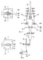
- the guide rollers 3a cannot change their positions quickly to thereby allow the front of the work 2 to be struck against them, as shown in FIG. 1. Impact force added is thus increased and their roll faces are chipping-damaged.
- Jpn. Pat. Appln. KOKAI Publication No. 2-42006 discloses a mechanism for adjusting the roll gap between the guide rollers.
- their roll gap is previously adjusted according to the size of a work rolled, and they are supported by a spring which has a small elastic modulus so as to allow them to change their positions quickly.
- the elastic modulus of the spring is made too small (or the spring is too weak)
- the guide rollers 3b are separated from each other to an excessive extent and their roll gap becomes too large accordingly.
- the work 2 is guided between the rolling rollers while being kept tilted, as shown in FIG. 2.
- the work 2 therefore, is not correctly rolled and it becomes a fault accordingly.
- it is not regularly contacted with the guide rollers 3b and this causes local stress to be concentrated somewhere on their roll faces. As the result, the roll faces of the guide rollers 3b are thus damaged.
- the object of the present invention is therefore to provide a system for guiding a work between rolling rollers while keeping it at right state but without chipping-damaging roll faces of the rolling rollers.
- a system for guiding a long work between rolling rollers comprising a section left substantially stationary independent of the work; a movable section slidable relative to the stationary section in a direction in which the work advances, at least a pair of guide rollers attached to the movable section to position just before or after the rolling rollers and having shafts substantially perpendicular to an axis of the rolling roller; and buffer means arranged in the movable section to absorb most of impact energy imparted to the guide rollers in the work advancing direction when the work passes between the guide rollers.
- the guide system further includes adjuster means for changing the stroke of a compression spring which serves as the buffer means.
- the guide system further includes a gap adjuster mechanism for adjusting a gap between the guide rollers and that the roll gap between the guide rollers is previously set by the gap adjuster mechanism according to the size of a work rolled.
- the movable section in the guide system includes a frame box opened at its front and rear ends, a lower slider assembly attached to the underside of the frame box to slide relative to the stationary section in an X-axis direction, and an upper slider assembly arranged in the top of the frame box to slide relative to the stationary section in the X-axis direction.
- impact force is added to the guide rollers when a tip of the work is introduced into the roll gap between them, and the movable section is moved in the work supply direction (or in the X-axis direction).
- Most of impact energy is absorbed this time by the buffer mechanism and the impact energy imparted to them can be thus reduced to a greater extent. Therefore, their roll faces can be less damaged.
- the roll gap is previously set not to cause them to change their positions in a direction perpendicular to the work supply direction (or in a Y-axis direction). The work, therefore, can keep its state correct or right.
- a hot rolling line 10 Arranged in a hot rolling line 10 are a heating furnace 11, an extracter 12, a roughing stand 13, a tilting table 14, intermediate rolling machines 15, 16, 17, finish rolling machines 18, take-up winders 19 and a coil conveyer 20.
- the hot rolling line 10 extends as a line from the heating furnace 11 to the roughing stand 13 and then as two lines from the intermediate rolling machines 15 to the take-up winders 19.
- a line material 2 is heated in the heating furnace 11, extracted on the tilting table 14 by the extracter 12, and roughed and divided into two by the roughing stand 13. They are then heat-rolled by the intermediate and finish rolling machines 15, 16, 17 and 18 and wound like coils by the take-up winders 19. These coils are then to a hook conveyer (not shown) by the coil conveyer 20.
- the guide system 40 for works according to an embodiment of the present invention is attached to each of the intermediate and finish rolling machines 15, 16, 17 and 18.
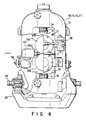
- the finish rolling machine 18 is a double horizontal stand of the closed head type and the guide system 40 is arranged at an entrance side of it.
- a housing 31 of the rolling machine 13 is clamp-fixed to a sole plate 28 by oil pressure units 29.
- a roll chock 32 Arranged in the housing 31 are a roll chock 32, rolling rollers 33a, 33b, a draft screw 34 and a path line adjusting screw 35.
- the guide system 40 is fixed to the housing 31 by a rest bar 36. Further, roll balance and thrust adjusting units 37 and 38 are attached to the rolling rollers 33a and 33b.
- guide rolls 66a and 66b of the guide system 40 are arranged just before the rolling rollers 33a and 33b to cause the work 2 to be caught between the rolling rollers 33a and 33b at once when it comes out of the guide rolls 66a and 66b.
- Shafts for guide rolls 66a and 66b are perpendicular to those for rolling rollers 33a and 33b.
- Each of guide rolls 66a and 66b is freely rotatably held by a holder 65 through a vertical shaft.
- the guide rollers 66a and 66b are made mainly of ceramics or cermet. Alternatively, they may be made heat-resistant pig casting steel and may have their roll surfaces coated with ceramics or cermet. Their roll surfaces may be either concaved or flat. In the present embodiment, the rollers 66a and 66b are made of ceramics and have a concaved roll surface each.
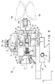
- the guide system 40 comprises a fixed section and a movable section 60.
- the fixed section includes a fixing base 41, a horizontal level block 43, a bracket 45, a side plate 46 and a cap block 70.
- the fixing base 41 is firmly fixed to the housing 31. Even when the work 2 is passing through the guide system 40, therefore, the fixed members 41, 43, 46 and 70 of the system 40 can be kept unmoved.
- the horizontal block 43 is connected and fixed to the fixing base 41 by bolts 42, the bracket 45 to the horizontal block 43 by bolts 44, the side plate 46 to the brackets 45 by a bolt 48 and the cap block 70 to the bracket 45 by a bolt 71.
- a slot 47 is formed in the side plate 46 to enable the side plate 46 to change its attached position along an axis X (or in a direction parallel to the path line).
- the cap block 70 has three cap bolts 72a and 72b and a slide ball 74 is attached to the lower end of each of the cap bolts 72a and 72b and it is fitted into a V-shaped groove 69 in an upper slide base 68 of the movable section 60.
- the V-shaped groove 69 extends along the axis X.
- the movable section 60 includes a lower slide base 61, a main block 62, a frame 63, an entrance 64, guide rolls 66a, 66b and the upper slide base 68.
- Four lower slider assemblies 80 are attached to the underside of the lower slide base 61.
- Each slider assembly 80 can slide on a slider rail 84 which is attached to the top of the horizontal level block 43.
- a push block 51b, a compression spring 52 and a cooling water passage (not shown) are arranged in the main block 62.
- the push block 51b is connected to an adjuster screw 51a. When the adjuster screw 51a is turned, the push block 51b is reciprocated in the direction of the axis X (or in the direction parallel to the path line) to push and release the compression spring 52.
- the compression spring 52 is used as a shock absorber or a buffer.
- a leaf spring, a hydraulic shock absorber, or the like may be employed in the present invention.
- the spring constant of the compression spring 52 is set in a range of 5 to 20 kg, or the spring modulus of the spring 52 is set in a range of 0.517 to 0.667 kgf/mm. It is preferable in this case that spring constants of the compression springs in the guide systems are set about 19 kg (0.667 ⁇ 28) in the intermediate rolling machine 15, about 15 kg (0.667 ⁇ 22), in the intermediate rolling machine 16, about 12 kg (0.667 ⁇ 18), in the intermediate rolling machine 17, and about 5.17 (0.517 ⁇ 10), in the finish rolling machine 18. These values are employed under those conditions that the cross area of the work 2 is 490 mm 2 in the machine 15, 254 mm 2 in the machine 16, 132 mm 2 in the machine 17 and 78.5 mm 2 in the machine 18.
- the adjuster screw 51a has a stroke of 15 mm, and the movable section 60 has a total weight of about 11.5 kg. Further, each of three V-shaped grooves 69 in the upper slider assembly has a face angle of 45° and a depth of 3.25 mm and each slide ball 74 has a diameter of 9.525 mm. Furthermore, thrust load added to the lower slider assembly 80 is 11 kg.
- Two supply pipes 54, the frame 63 and the entrance 64 are attached to the front of the movable section 60.
- the two supply pipes 54 are communicated with their corresponding internal passages (not shown) in the main block 62.
- cooling water is supplied from a cooling water supply source (not shown) into the internal passages through the supply pipes 54, water is sprayed to the work 2 and the guide rolls 66a, 66b.
- the frame 63 serves as a member for reinforcing the front of the movable section 60.
- the entrance 64 has a conical shape and a guide hole 64a is formed in a smaller-diameter portion of this entrance 64.
- the guide hole has such a shape that allows the work 2 having an oval section to pass through it.
- the paired right and left guide rolls 66a and 66b have a gap G 1 of about 3 mm between their outermost circumferences and a gap G 2 of about 8 mm between their recess bottoms. Each of them has an outer diameter of 45 mm and a width of 24.5 mm. Further, each of ceramics rolls 66a 66b has a weight of about 0.1 kg.
- the guide rolls 66a and 66b are exchanged with others having a different size to change their gaps G 1 and G 2 in this example, they may be moved in the direction of an axis Y by a roll gap adjuster mechanism (not shown). It is preferable in this case that they are arranged to change their positions together with their holders 65.
- cap bolts 72a and 72b are arranged in the upper slider assembly to position at vertexes of a triangle.
- the center bolt 72a is positioned behind the other two bolts 72b in the direction of the axis X to thereby arrange the slide balls 74 in a triangle. This makes it quite possible to prevent the guide rolls 66a and 66b from oscillating their heads (or reciprocating their heads in the direction of the axis Y).
- two rails 84 are arranged on the horizontal level block 43, extending in the X-axis direction, so that the movable section 60 supported by four lower slider assemblies 80 can move along the rails 84.
- Each of the rails 84 is fixed to the block 43 by bolts 88.
- a main member 81 of each lower slider assemblies 80 are attached to the underside of the movable section by four bolts 87.
- grooves 84a are formed in both sides of each rail 84 and bearing balls 86 are fitted in each of the grooves 84a.
- a groove 82a is formed in a side of each of sub-members 82 and the bearing balls 86 are also fitted into the groove 82a.
- the bearing balls 86 are held in both grooves 82a and 84a to thereby a linear bearing movable in the X-axis direction. Further, the bearing balls 86 are held by a thin plate 85 not to come out of the grooves 82a and 84a.
- the work 2 which is just about to be finish-rolled is a steel line material having an oval section which is 13 mm long in a Z-axis direction and 8 mm long in the Y-axis direction. Its surface temperature is about 1050°C. It is continuously supplied to the rolling machine 18 at a speed of 6m per second. Its supply speed can be variously changed in a range of 1 to 100m per second. When its supply speed is in this range, it can be correctly rolled by the rolling machine 18 which is provided with the guide system 40.
- the work 2 advances to the finish rolling machine 18 after it passed through the intermediate rolling machine 17. Its front 2a enters into the system 40 through the entrance hole 64a and reaches the guide rollers 66a and 66b. Water sprayed prevents the guide rollers 66a and 66b from being overheated and also raises the lubrication of it between the guide rollers 66a and 66b. When it passes through the guide rollers 66a and 66b, it adds impact to them.
- the guide rollers 66a and 66b When the guide rollers 66a and 66b receives impact, they change their positions in the Y-axis direction (or in the direction in which the work 2 is supplied). Impact force added directly to their roll faces can be thus reduced to a greater extent. This impact reduction can be achieved with a higher response. When impact is reduced like this at the initial rolling process, the spring 52 returns to its original state.
- Position changing of the guide rollers 66a and 66b in the Y-axis direction can be made less or none. Therefore, the work 2 can be more correctly held and caught between the guide rollers 66a and 66b. It is then rolled from above and below by the rolling rolls 33a and 33b to thereby reduce its sectional area. After this finish rolling process, the work 2 becomes round, and the diameter of the work 2 is about 9.5 mm.
- the movable section 60 can move in the supply direction of the work 2 (or in the X-axis direction) and most of impact energy added can be absorbed by the compression spring 52 when impact is added to the guide rollers 66a and 66b.
- impact energy added directly to the guide rollers 66a and 66b themselves can be reduced to a greater extent and this more effectively prevents their roll faces from being chipping-damaged.
- the roll gaps G 1 and G 2 are previously set not to cause the guide rollers 66a and 66b to change their positions in the supply direction of the work 2 (or in the Y-axis direction). Therefore, the state of the work 2 can be kept more correct. As the result, it can be more correctly caught between the rolling rolls 33a and 33b. It can be thus rolled without any distortion.
- three slide balls 74 of the upper slider assembly are arranged in a triangle.
- the guide rollers 66a and 66b can be thus more effectively prevented from oscillating their heads (or reciprocating in the Y-axis direction) when the work 2 is passing through them.
- the work 2 rolled has been a carbon steel line material in the above example, it may be other materials such as stainless steel and titanium lines.
- the work 2 rolled has had an oval section, it may has other sections such as hexagon and rectangle.
- the guide rollers may be located at the outlet of the rolling rollers, not at the inlet thereof as in the embodiment described above.
- the rolling machine incorporating the guide rollers is of closed-head type. Nonetheless, the guide rollers may be incorporated in a rolling machine of open-heat type.
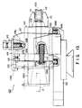
- Reference numeral 101 represents a guide box which is opened at its front and rear ends and having a reversed-U shaped section.
- a passage 101a having a rectangular section is formed in it.
- Thick side plates 102 are attached to its both sides and it is fixed to a horizontal level block 103 through these side plates 102.
- a movable section 104 having a work introducing space 104a is inserted into its passage 101a to freely reciprocate along the passage 101a.
- a collar stopper 105 is arranged integral at the rear end portion of the movable section 104 and a tapered entrance 106 of an introduction member for introducing the work 2 into the guide system 100 is projected backwards from the collar stopper 105.
- a slide key 107 having a rectangular section is formed in the center top of the block 103.
- Plural freely-rotatable balls 108 are projected from the top of the block 103 on both sides of the slide key 107.
- a ball 108b is projected downwards from the top ceiling of the guide box 101.
- the movable section 104 is held between the balls 108a and the ball 108b and the slide key 107 is fitted into a groove 109 in the bottom of the movable section 104, so that the movable section 104 can be reciprocated in the X-axis direction.
- the balls 108a and 108b are urged by coil springs 108c.
- a pair of roller supports 110 are attached to the front of the movable section 104, projecting their front portions from it.
- Guide rollers 112a and 112b are freely rotatably supported by the roller supports 110 through shafts 111.
- the base end of each roller support 110 is adjustably attached to the movable section 104 by a torsion element (not shown) to adjust a roll gap G 3 between the guide rollers 112a and 112b.
- Recesses 105a are formed in the inner face of the stopper 105 at the lower portion thereof. Recesses 102a are also formed in the inner faces of the thick side plates 102 at those portions thereof which correspond to the recesses 105a in the stopper 105. Both ends of a coil spring 113 are embedded in and fixed to bottoms of these recesses 105a and 102a to separate the stopper 105 and the side plate 102 from each other.
- the base of a movement adjuster plate 114 having a stopper 114a which is bent like a fallen L at the front thereof is fixed to the top of the guide box 101.
- a movement adjuster pin 116 is projected from the rear face of the guide box 101 at the upper portion thereof, corresponding to the stopper 114a of the plate 114.
- the movement adjuster pin 116 is fitted into a torsion element hole 101 in the rear face of the guide box 101 at the upper portion thereof, thereby adjusting the extent to which the pin 116 is projected from the rear face of the guide box 101.
- the stopper 105 can be reciprocated between the stopper 114a and the head of the pin 116. Its stroke “S” can be adjusted by the pin 116. Its stroke "S” is decided depending upon such conditions as the diameter and supply speed of a work 2.
- the stopper 105 is usually urged against the stopper 114a by a coil spring 113.
- coil spring 113 has been used as a damper member in the above-described example, other elastic means such as the plate spring and air cushion may be used instead.
- the roll gap G 3 is previously set not to cause the guide rollers to change their positions in the direction perpendicular to the work supply direction (or in the Y-axis direction).
- the state of the work 2 can be thus kept more correct. Therefore, the work 2 can be more correctly caught between the rolling rollers 33a and 33b and rolled without any distortion by them.
- the movable section is moved in the work supply direction (or in the Y-axis direction) and most of impact energy can be absorbed by the damper mechanism, when impact is added to the guide rollers.
- impact energy added to the guide rollers themselves can be reduced to a greater extent. This prevents their roll faces from being damaged.
- the roll gap is previously set not to cause the guide rollers to change their positions in the work supply direction (or in the Y-axis direction). The state of the work can be thus kept more correct.
Landscapes
- Engineering & Computer Science (AREA)
- Mechanical Engineering (AREA)
- Metal Rolling (AREA)
Priority Applications (1)
| Application Number | Priority Date | Filing Date | Title |
|---|---|---|---|
| EP95306978A EP0767013A1 (de) | 1995-10-02 | 1995-10-02 | System zum Führen von Walzgut |
Applications Claiming Priority (1)
| Application Number | Priority Date | Filing Date | Title |
|---|---|---|---|
| EP95306978A EP0767013A1 (de) | 1995-10-02 | 1995-10-02 | System zum Führen von Walzgut |
Publications (1)
| Publication Number | Publication Date |
|---|---|
| EP0767013A1 true EP0767013A1 (de) | 1997-04-09 |
Family
ID=8221350
Family Applications (1)
| Application Number | Title | Priority Date | Filing Date |
|---|---|---|---|
| EP95306978A Ceased EP0767013A1 (de) | 1995-10-02 | 1995-10-02 | System zum Führen von Walzgut |
Country Status (1)
| Country | Link |
|---|---|
| EP (1) | EP0767013A1 (de) |
Cited By (1)
| Publication number | Priority date | Publication date | Assignee | Title |
|---|---|---|---|---|
| CN113560353A (zh) * | 2021-07-16 | 2021-10-29 | 合肥东方节能科技股份有限公司 | 一种带有预校准机构的滚动导卫 |
Citations (5)
| Publication number | Priority date | Publication date | Assignee | Title |
|---|---|---|---|---|
| DE1427188A1 (de) * | 1960-03-22 | 1969-04-03 | Nyby Bruk Ab | Fuehrungskasten fuer Walzwerke |
| EP0013671A1 (de) * | 1979-01-24 | 1980-08-06 | Kotobuki Sangyo Kabushiki Kaisha | Zentrier- und Regelvorrichtung zur Regelung des Abstandes zwischen den Führungsrollen einer Materialführung bei Walzwerken |
| US4700875A (en) * | 1984-09-13 | 1987-10-20 | Mario Fabris | Roller entry guide |
| JPH0266135A (ja) * | 1988-08-31 | 1990-03-06 | Kobe Steel Ltd | 熱間ガイドローラ用サーメット |
| JPH0242006B2 (de) | 1985-05-20 | 1990-09-20 |
-
1995
- 1995-10-02 EP EP95306978A patent/EP0767013A1/de not_active Ceased
Patent Citations (5)
| Publication number | Priority date | Publication date | Assignee | Title |
|---|---|---|---|---|
| DE1427188A1 (de) * | 1960-03-22 | 1969-04-03 | Nyby Bruk Ab | Fuehrungskasten fuer Walzwerke |
| EP0013671A1 (de) * | 1979-01-24 | 1980-08-06 | Kotobuki Sangyo Kabushiki Kaisha | Zentrier- und Regelvorrichtung zur Regelung des Abstandes zwischen den Führungsrollen einer Materialführung bei Walzwerken |
| US4700875A (en) * | 1984-09-13 | 1987-10-20 | Mario Fabris | Roller entry guide |
| JPH0242006B2 (de) | 1985-05-20 | 1990-09-20 | ||
| JPH0266135A (ja) * | 1988-08-31 | 1990-03-06 | Kobe Steel Ltd | 熱間ガイドローラ用サーメット |
Non-Patent Citations (1)
| Title |
|---|
| PATENT ABSTRACTS OF JAPAN vol. 014, no. 246 (C - 0722) 25 May 1990 (1990-05-25) * |
Cited By (1)
| Publication number | Priority date | Publication date | Assignee | Title |
|---|---|---|---|---|
| CN113560353A (zh) * | 2021-07-16 | 2021-10-29 | 合肥东方节能科技股份有限公司 | 一种带有预校准机构的滚动导卫 |
Similar Documents
| Publication | Publication Date | Title |
|---|---|---|
| KR101320930B1 (ko) | 슬래브 가공 방법 및 장치 | |
| RU2547062C2 (ru) | Прокатный стан для изготовления металлической полосы и способ изготовления прокатного стана | |
| US5241903A (en) | Guard for the nips of rolls in calenders and the like | |
| US20110132055A1 (en) | Rolling device | |
| JP4316796B2 (ja) | 精密圧延方法 | |
| EP0767013A1 (de) | System zum Führen von Walzgut | |
| KR100360933B1 (ko) | 수평금속바압출프레스 | |
| US4643013A (en) | Coil guide system for hot strip mills | |
| KR100973905B1 (ko) | 선재의 압연 소재 가이드장치 | |
| US5016400A (en) | Pressure bar for a belt grinding machine | |
| CA1230730A (en) | Belt support for a twin-belt continuous casting mold | |
| KR102170940B1 (ko) | 압연기의 레스트바 장치 | |
| CZ297024B6 (cs) | Válcovací stolice pro válcování kovového pásovéhomateriálu zatepla nebo zastudena | |
| KR101064173B1 (ko) | T형강 열간 압연 라인의 냉각 장치, t형강의 제조 설비 및, 제조 방법 | |
| JPS61253113A (ja) | 熱間圧延機用の遮熱装置 | |
| US4974437A (en) | Rolling mill stand | |
| EP2697003B1 (de) | Transportwalzenanordnung und verfahren zum betreiben einer transportwalzenanordnung | |
| KR20150134450A (ko) | 스트립 안내 장치 | |
| KR0184289B1 (ko) | 업세팅프레스의 프레스공구지지체 및 크랭크하우징을 인장지지 및 균형화시키기 위한 장치 | |
| KR100775472B1 (ko) | 연속 선재압연 설비의 빌레트 유도용 가이드 폭 자동조절장치 | |
| US5220819A (en) | Entry guide for strip mill | |
| KR102379572B1 (ko) | 업 루퍼 장치 | |
| RU2201826C2 (ru) | Машина для правки листового проката | |
| JPH07275915A (ja) | 圧延ローラーガイド機構 | |
| KR100504356B1 (ko) | 판 또는 스트립 압연용 압연기 |
Legal Events
| Date | Code | Title | Description |
|---|---|---|---|
| PUAI | Public reference made under article 153(3) epc to a published international application that has entered the european phase |
Free format text: ORIGINAL CODE: 0009012 |
|
| 17P | Request for examination filed |
Effective date: 19951101 |
|
| AK | Designated contracting states |
Kind code of ref document: A1 Designated state(s): GB SE |
|
| 17Q | First examination report despatched |
Effective date: 19990319 |
|
| GRAG | Despatch of communication of intention to grant |
Free format text: ORIGINAL CODE: EPIDOS AGRA |
|
| STAA | Information on the status of an ep patent application or granted ep patent |
Free format text: STATUS: THE APPLICATION HAS BEEN REFUSED |
|
| 18R | Application refused |
Effective date: 20010216 |