EP0767016B1 - Verfahren und Vorrichtung zum Feststellen von Radien bei Biegeteilen - Google Patents
Verfahren und Vorrichtung zum Feststellen von Radien bei Biegeteilen Download PDFInfo
- Publication number
- EP0767016B1 EP0767016B1 EP19960115724 EP96115724A EP0767016B1 EP 0767016 B1 EP0767016 B1 EP 0767016B1 EP 19960115724 EP19960115724 EP 19960115724 EP 96115724 A EP96115724 A EP 96115724A EP 0767016 B1 EP0767016 B1 EP 0767016B1
- Authority
- EP
- European Patent Office
- Prior art keywords
- fact
- roller
- bending
- centre
- cylinder
- Prior art date
- Legal status (The legal status is an assumption and is not a legal conclusion. Google has not performed a legal analysis and makes no representation as to the accuracy of the status listed.)
- Expired - Lifetime
Links
- 238000000034 method Methods 0.000 title claims description 18
- 238000005452 bending Methods 0.000 claims description 30
- 230000006835 compression Effects 0.000 description 6
- 238000007906 compression Methods 0.000 description 6
- 238000006073 displacement reaction Methods 0.000 description 3
- 230000002349 favourable effect Effects 0.000 description 1
- 238000005259 measurement Methods 0.000 description 1
- 238000013000 roll bending Methods 0.000 description 1
Images

Classifications
-
- B—PERFORMING OPERATIONS; TRANSPORTING
- B21—MECHANICAL METAL-WORKING WITHOUT ESSENTIALLY REMOVING MATERIAL; PUNCHING METAL
- B21D—WORKING OR PROCESSING OF SHEET METAL OR METAL TUBES, RODS OR PROFILES WITHOUT ESSENTIALLY REMOVING MATERIAL; PUNCHING METAL
- B21D7/00—Bending rods, profiles, or tubes
- B21D7/14—Bending rods, profiles, or tubes combined with measuring of bends or lengths
-
- B—PERFORMING OPERATIONS; TRANSPORTING
- B21—MECHANICAL METAL-WORKING WITHOUT ESSENTIALLY REMOVING MATERIAL; PUNCHING METAL
- B21D—WORKING OR PROCESSING OF SHEET METAL OR METAL TUBES, RODS OR PROFILES WITHOUT ESSENTIALLY REMOVING MATERIAL; PUNCHING METAL
- B21D7/00—Bending rods, profiles, or tubes
- B21D7/08—Bending rods, profiles, or tubes by passing between rollers or through a curved die
Definitions
- the invention relates to a method for determining Radii in - bending parts defining - two cylinder surfaces, an inner cylindrical surface having a center of curvature facing as well as a second - outer - cylinder surface this is turned away.
- the invention also covers a device particularly suitable for this method.
- a portable device for bending pipes is an example can be found in DE-PS 32 09 539.
- a measurement the curvature can be done, for example, by hand using a Three-point measuring device.
- Radii can be curved Objects, for example with the so-called three-point measuring method, using strain gauges and measuring methods, where - touching or non-contact - several Detects points on a contour and uses this to calculate the radius becomes (see for example GB-A-2087561), however, many of these methods are either relatively imprecise or tied to boundary conditions that in can hardly be followed in practice.
- the inventor was aware of this state of the art set the goal, a measuring method and a device to develop with the help of the radius of the arc of bent parts by means of fewer and easy to grasp geometrical Sizes can be determined.
- the length of the radius of the inner cylinder surface closer to the center of curvature is determined as a quotient from the radial distance between the two cylinder surfaces as a dividend and a divisor which is the difference of the quotient of the arc length of the outer cylinder surface by the arc length of the inner cylinder surface minus the subtrahend 1.
- the three geometric sizes are determined using two - preferably identical - friction wheel encoder units, which are arranged opposite each other; each this unit is mounted on a separate carriage, and both sledges can be independent of each other be moved on a common linear guide.
- Each one of these Sled is an energy store, especially one Compression spring, assigned. Thanks to this requirement is a continuous Ensure that the friction wheels rest on the curved object; this is between the two described Friction wheels. That continuous plant of Friction wheels are supported by the proviso that the Compression spring of the outer slide with a higher force is equipped as the compression spring of the inner slide.
- the distance between the Cylinder surfaces with a displacement transducer known per se in a bending machine or outside of it - for example with a handheld meter - be measured on the bent part.
- the distance between the carriage can also be detected by a displacement sensor; this Distance corresponds to the width of the curved object.
- Rod 10 corresponds to the distance from its outer Side surface 12 to that not recognizable in the drawing Center of curvature of the sum of the rod width b and the inner bending radius Ri, i.e. the distance of the inner one Side surface 14 to that center of curvature.
- Each of the two side surfaces 12, 14 determine one of two to each other equidistant cylinder surface sections.
- the acquisition of the three geometric sizes is in the Made that the arc lengths La, Li by means of a outer and an inner friction wheel encoder 16 and 18 as well the distance b between the two cylinder or side surfaces 12.14 by a potentiometric displacement sensor be determined.
- the friction wheel rotary encoders 16, 18 are located on two slides 20, 20 i , which can move independently of one another on a linear guide 22 oriented radially to the arc segment.
- a continuous application of the friction wheels 17 of that friction wheel encoder units 16,18 at those side faces 12,14 is achieved i with two compression springs 24,24, the i are supported in each case at one end to the carriage 24 and 24 respectively. Since the outer compression spring 24 exerts a higher force on its slide 20 than the inner compression spring 24 i on the inner slide 20 i , a continuous application of guide rollers 26 on the curved rod 10 is achieved at the same time.
- the guide rollers 26 are two at the ends - each offered by part of a guide beam 28 - side arms of a T-shaped guide tree 30 in plan view fixed, the central bar forms that linear guide 22. Their necessary radial alignment is compared to that of you reach the guide bar 28 protruding at right angles, from the free ends of each one - for linear guidance parallel - bearing arm 32 protrudes for those guide rollers 26.
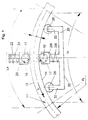
- FIG. 2 shows the measuring device integrated to capture the two arc lengths of the bent part in a typical three-roll bending machine with bending rolls 35 to 37.
- the main difference to the execution 1 is that the measuring unit in FIG. 2 has no guide bar 22 with guide rollers 26, the other version for the continuous radial Alignment of the measuring unit on the bent part ensures. Instead, the common linear guide 22 on the machine body after previous alignment either in steps adjustable - or not adjustable - attached.
- the linear guide 22 can either be behind the bending roller 37 or even just before the bending roller 37 in the feed direction x seen, i.e. in the space between middle role 35 and bending roller 37 are positioned.
Landscapes
- Engineering & Computer Science (AREA)
- Mechanical Engineering (AREA)
- A Measuring Device Byusing Mechanical Method (AREA)
- Length Measuring Devices With Unspecified Measuring Means (AREA)
Description
sowie
Claims (17)
- Verfahren zum Feststellen von Radien bei zwei Zylinderflächen bestimmenden Biegeteilen (10), wobei eine innere Zylinderfläche (14) einem Krümmungsmittelpunkt zugewandt sowie eine zweite Zylinderfläche (12) diesem abgewandt ist,
dadurch gekennzeichnet,
daß die Länge des Radius (Ri) der dem Krümmungsmittelpunkt näherliegenden inneren Zylinderfläche (14) als Quotient aus dem radialen Abstand (b) der beiden Zylinderflächen (14,12) als Divident und einem Divisor bestimmt wird, der die Differenz des Quotienten der Bogenlänge (La) der äußeren Zylinderfläche durch die Bogenlänge (Li) der inneren Zylinderfläche abzüglich des Subtrahenden 1 ist. - Verfahren nach Anspruch 1, dadurch gekennzeichnet, daß der radiale Abstand (b) zwischen den Zylinderflächen (12,14) nach dem Erfassen der Bogenlängen (Li,La) gemessen wird.
- Verfahren nach Anspruch 1 oder 2, dadurch gekennzeichnet, daß die Bogenlängen (Li,La) beim Biegen in mehreren Umformstufen unabhängig von der radialen Ausrichtung gemessen werden.
- Verfahren nach einem der Ansprüche 1 bis 3, dadurch gekennzeichnet, daß wenigstens eine der Bogenlängen (Li, La) berührungslos gemessen werden.
- Vorrichtung zur Durchführung des Meßverfahrens nach einem der Ansprüche 1 bis 4, dadurch gekennzeichnet, daß zwei Reibrad-Drehgeber-Einheiten (16,18) eine Durchgangsöffnung für das Biegeteil (10) bestimmen, wobei jede der Reibrad-Drehgeber-Einheiten auf einem Schlitten (20,20i) angeordnet und beide Schlitten auf einer gemeinsamen Linearführung (22) verschieblich sind, wobei die Linearführung (22) radial zum sich in der durchgangsöffnung befindlichen, gekrümmten beigeteil (10) ausrichtbar ist.
- Vorrichtung nach Anspruch 5, dadurch gekennzeichnet, daß sich jeder Schlitten (20,20i) an seiner dem Biegeteil (10) abgekehrten Seite gegen einen Kraftspeicher (24,24i) abstützt.
- Vorrichtung nach Anspruch 5 oder 6, dadurch gekennzeichnet, daß die Linearführung (22) Teil eines Führungsbaumes (30) ist und dieser einen ihn querenden Führungsbalken (28) enthält, an dessen freien Enden jeweils eine Führungsrolle (26) für das Biegeteil angeordnet ist.
- Vorrichtung nach einem der Ansprüche 5 bis 7, dadurch gekennzeichnet, daß der Führungsbalken (28) in sich gekrümmt ist.
- Vorrichtung nach Anspruch 7, dadurch gekennzeichnet, daß der Führungsbalken (28) zur Linearführung (22) rechtwinkelig ausgebildet ist.
- Vorrichtung nach einem der Ansprüche 7 bis 9, dadurch gekennzeichnet, daß von den freien Enden des Führungsbalkens (28) jeweils ein Tragarm (32) für eine Führungsrolle (26) abragt.
- Vorrichtung nach Anspruch 10, dadurch gekennzeichnet, daß der Tragarm (32) zur Linearführung (22) etwa parallel verläuft.
- Vorrichtung nach wenigstens einem der Ansprüche 6 bis 11, dadurch gekennzeichnet, daß der Kraftspeicher des radial außenliegenden Schlittens (20) mit einer größeren Kraft versehen ist als der Kraftspeicher (24i) des radial innenliegenden Schlittens (20i).
- Vorrichtung nach einem der Ansprüche 5 bis 12, gekennzeichnet durch einen Wegaufnehmer zur Aufnahme des Abstandes (b) zwischen den Schlitten (20,20i) bzw. den Zylinderflächen (12,14) des Biegeteils (10).
- Vorrichtung nach einem der Ansprüche 5 bis 13, dadurch gekennzeichnet, daß den Schlitten (20, 20i) in Förderrichtung (x) beidseits der Bewegungsbahn für den Strang (10) der Umfang wenigstens einer Rolle (35, 36, 37) vorgeordnet ist.
- Vorrichtung nach einem der Ansprüche 5 bis 14, dadurch gekennzeichnet, daß die gemeinsame Linearführung (22) mit den Schlitten (20, 20i) in dem Raum zwischen einer Mittelrolle (35) und einer Biegerolle (37) angeordnet ist, bevorzugt in Vorschubrichtung (x) kurz vor der Biegerolle.
- Vorrichtung nach Anspruch 14 oder 15, dadurch gekennzeichnet, daß an der Krümmungsinnenseite des Stranges (10) eine Mittelrolle (35) vorgesehen ist, der an der Krümmungsaußenseite eine Führungsrolle (36) sowie eine schlittennahe Biegerolle (37) gegenüberliegen.
- Vorrichtung nach einem der Ansprüche 14 bis 16, dadurch gekennzeichnet, daß die Führungsrolle (36) und die Biegerolle (37) auf unterschiedlichen Seiten einer durch den Mittelpunkt (M) der Mittelrolle (35) gelegten diametralen Mittelachse (Q) angeordnet sind.
Applications Claiming Priority (2)
| Application Number | Priority Date | Filing Date | Title |
|---|---|---|---|
| DE19536938 | 1995-10-04 | ||
| DE19536938 | 1995-10-04 |
Publications (3)
| Publication Number | Publication Date |
|---|---|
| EP0767016A2 EP0767016A2 (de) | 1997-04-09 |
| EP0767016A3 EP0767016A3 (de) | 1997-12-03 |
| EP0767016B1 true EP0767016B1 (de) | 1999-06-02 |
Family
ID=7773990
Family Applications (1)
| Application Number | Title | Priority Date | Filing Date |
|---|---|---|---|
| EP19960115724 Expired - Lifetime EP0767016B1 (de) | 1995-10-04 | 1996-10-01 | Verfahren und Vorrichtung zum Feststellen von Radien bei Biegeteilen |
Country Status (2)
| Country | Link |
|---|---|
| EP (1) | EP0767016B1 (de) |
| DE (1) | DE19602504A1 (de) |
Families Citing this family (6)
| Publication number | Priority date | Publication date | Assignee | Title |
|---|---|---|---|---|
| IT1394105B1 (it) * | 2009-05-06 | 2012-05-25 | Cml Int Spa | Macchina per curvare in modo continuo un pezzo allungato secondo raggi predeterminati |
| IT1400500B1 (it) * | 2010-06-22 | 2013-06-11 | Crippa Spa | Procedimento per la curvatura di tubi, fili o nastri di metallo a serpentina o a molla e macchinaper curva tubi, fili o nastri di metallo per la fabbricazione di una serpentina o una molla presentante un andamento ad elica comprendente una pluralità di spire |
| ITTO20130936A1 (it) * | 2013-11-19 | 2015-05-20 | Cte Sistemi Srl | Gruppo di misura per misurare il raggio di curvatura e l'avanzamento in una macchina curvatrice, in particolare in una macchina curvatrice per la curvatura di conduttori per bobine superconduttive |
| DE102016013144A1 (de) * | 2016-10-31 | 2018-05-03 | Technische Universität Dortmund | Vorrichtung zur taktilen Erfassung und Analyse der Geometrie von gebogenen Profilen oder Rohren |
| DE102020127164B3 (de) * | 2020-10-15 | 2021-07-15 | Jenoptik Industrial Metrology Germany Gmbh | Radialkraft-Vorrichtung für ein Konturmessgerät und Messsystem |
| CN113884958B (zh) * | 2021-09-27 | 2023-07-25 | 中国科学院合肥物质科学研究院 | 一种测量超导带材临界侧弯半径的装置及方法 |
Family Cites Families (5)
| Publication number | Priority date | Publication date | Assignee | Title |
|---|---|---|---|---|
| CH572200A5 (de) * | 1973-09-18 | 1976-01-30 | Haeusler Christian Ag | |
| DE3041212C2 (de) * | 1980-11-03 | 1982-08-26 | August Wilhelm 5901 Wilnsdorf Schäfer | Vorrichtung zum Biegen, insbesondere Runden von Blechen oder Profilen |
| GB2087561A (en) * | 1980-11-11 | 1982-05-26 | Smt Pullmax | Apparatus for measuring the curvature of a single-curved surface |
| US4532787A (en) * | 1981-03-16 | 1985-08-06 | C.M.L. Costruzioni Meccaniche Liri S.R.L. | Portable electromechanically-controlled pipe-bending apparatus |
| DE4225878C2 (de) * | 1992-08-05 | 1996-02-29 | Bayer Isolierglasfab Kg | Verfahren und Vorrichtung zum Biegen eines Bogens an einem hohlen Abstandhalterprofil |
-
1996
- 1996-01-25 DE DE19602504A patent/DE19602504A1/de not_active Withdrawn
- 1996-10-01 EP EP19960115724 patent/EP0767016B1/de not_active Expired - Lifetime
Also Published As
| Publication number | Publication date |
|---|---|
| EP0767016A3 (de) | 1997-12-03 |
| DE19602504A1 (de) | 1997-04-10 |
| EP0767016A2 (de) | 1997-04-09 |
Similar Documents
| Publication | Publication Date | Title |
|---|---|---|
| EP0916425B1 (de) | Rollenrichtmaschine zum Richten eines Walzprofils | |
| DE69106707T2 (de) | Einrichtung an einer wickelmaschine für kabel oder ähnliches strangartiges produkt. | |
| EP0494430B1 (de) | Verfahren zur Messung des Durchmessers von Zylindern, insbesondere von Walzen | |
| DE10131461C1 (de) | Anlage zum Zusammenfügen und Längsschweißen von aus Blechen oder dergleichen gebogenen Rohren | |
| EP0767016B1 (de) | Verfahren und Vorrichtung zum Feststellen von Radien bei Biegeteilen | |
| DE3816130C2 (de) | ||
| AT506313A4 (de) | Biegegesenk für eine biegepresse, insbesondere abkantpresse | |
| DE7010870U (de) | Vorrichtung zum schleifen der oberflaeche von gedrechselten gegenstaenden. | |
| DE2704122A1 (de) | Andrueckvorrichtung fuer eine drahtwickelmaschine | |
| EP0348340B1 (de) | Verfahren und Vorrichtung zur Erfassung des Achsverlaufes eines langgestreckten, zylindrischen Körpers | |
| CH659520A5 (de) | Vorrichtung zum ausmessen der lenkgeometrie von kraftfahrzeugen. | |
| DE3211489A1 (de) | Verfahren und vorrichtung zur korrektur von sollform-abweichungen platisch verformbarer gegenstaende | |
| DE19502918A1 (de) | Vorrichtung zur kontinuierlichen Herstellung längsnahtgeschweißter dünnwandiger schraubenlinien- oder ringförmig gewellter Metallrohre | |
| EP1218122A1 (de) | Richtmaschine zum richten langgestreckter körper | |
| EP0033310A1 (de) | Messeinrichtung an einer von drehgelagerten Rollen gebildeten Rollenbahn sowie Verfahren zur Auswertung der Messwerte | |
| DE3308283C2 (de) | Vorrichtung und Verfahren zum Aufwickeln von Kabeln oder biegsamen Leitungen auf Trommeln und ein Verfahren zum Justieren der Vorrichtung von Beginn des Wickelvorganges | |
| EP3517923B1 (de) | Vortriebseinrichtung für inspektionssystem | |
| EP0384477A2 (de) | Verfahren und Maschine zum Biegen von Rohren | |
| WO2022017969A1 (de) | Drahtfördervorrichtung und verfahren | |
| DE19510330C2 (de) | Biegegerät | |
| DE102005013746B4 (de) | Backenprofilwalze | |
| DE3815304A1 (de) | Verfahren und vorrichtung zum biegen bzw. richten von profilen und baendern mit walzen bzw. rollen | |
| DE4318928C1 (de) | Verfahren zur Installation eines Leitungsrohrsystems | |
| EP0513432A1 (de) | Vorrichtung zur Ermittlung des Durchhanges einer laufenden Materialbahn quer zu ihrer Längsrichtung | |
| DE3512290A1 (de) | Messeinrichtung zum messen des spaltes zwischen zwei walzen oder rollen sowie verfahren zur durchfuehrung der messung |
Legal Events
| Date | Code | Title | Description |
|---|---|---|---|
| PUAI | Public reference made under article 153(3) epc to a published international application that has entered the european phase |
Free format text: ORIGINAL CODE: 0009012 |
|
| AK | Designated contracting states |
Kind code of ref document: A2 Designated state(s): CH FR IT LI NL SE |
|
| PUAL | Search report despatched |
Free format text: ORIGINAL CODE: 0009013 |
|
| AK | Designated contracting states |
Kind code of ref document: A3 Designated state(s): CH FR IT LI NL SE |
|
| 17P | Request for examination filed |
Effective date: 19980416 |
|
| GRAG | Despatch of communication of intention to grant |
Free format text: ORIGINAL CODE: EPIDOS AGRA |
|
| GRAG | Despatch of communication of intention to grant |
Free format text: ORIGINAL CODE: EPIDOS AGRA |
|
| GRAH | Despatch of communication of intention to grant a patent |
Free format text: ORIGINAL CODE: EPIDOS IGRA |
|
| 17Q | First examination report despatched |
Effective date: 19980805 |
|
| GRAH | Despatch of communication of intention to grant a patent |
Free format text: ORIGINAL CODE: EPIDOS IGRA |
|
| GRAA | (expected) grant |
Free format text: ORIGINAL CODE: 0009210 |
|
| AK | Designated contracting states |
Kind code of ref document: B1 Designated state(s): CH FR IT LI NL SE |
|
| PG25 | Lapsed in a contracting state [announced via postgrant information from national office to epo] |
Ref country code: SE Free format text: THE PATENT HAS BEEN ANNULLED BY A DECISION OF A NATIONAL AUTHORITY Effective date: 19990602 Ref country code: NL Free format text: LAPSE BECAUSE OF FAILURE TO SUBMIT A TRANSLATION OF THE DESCRIPTION OR TO PAY THE FEE WITHIN THE PRESCRIBED TIME-LIMIT Effective date: 19990602 Ref country code: IT Free format text: LAPSE BECAUSE OF FAILURE TO SUBMIT A TRANSLATION OF THE DESCRIPTION OR TO PAY THE FEE WITHIN THE PRESCRIBED TIME-LIMIT;WARNING: LAPSES OF ITALIAN PATENTS WITH EFFECTIVE DATE BEFORE 2007 MAY HAVE OCCURRED AT ANY TIME BEFORE 2007. THE CORRECT EFFECTIVE DATE MAY BE DIFFERENT FROM THE ONE RECORDED. Effective date: 19990602 Ref country code: FR Free format text: LAPSE BECAUSE OF FAILURE TO SUBMIT A TRANSLATION OF THE DESCRIPTION OR TO PAY THE FEE WITHIN THE PRESCRIBED TIME-LIMIT Effective date: 19990602 |
|
| REG | Reference to a national code |
Ref country code: CH Ref legal event code: EP |
|
| EN | Fr: translation not filed | ||
| PLBE | No opposition filed within time limit |
Free format text: ORIGINAL CODE: 0009261 |
|
| STAA | Information on the status of an ep patent application or granted ep patent |
Free format text: STATUS: NO OPPOSITION FILED WITHIN TIME LIMIT |
|
| 26N | No opposition filed | ||
| PG25 | Lapsed in a contracting state [announced via postgrant information from national office to epo] |
Ref country code: LI Free format text: LAPSE BECAUSE OF NON-PAYMENT OF DUE FEES Effective date: 20001031 Ref country code: CH Free format text: LAPSE BECAUSE OF NON-PAYMENT OF DUE FEES Effective date: 20001031 |
|
| REG | Reference to a national code |
Ref country code: CH Ref legal event code: PL |