EP0767045A2 - Dispositif d'entraînement électro-hydraulique pour un mandrin de soufflage d'une machine de moulage par soufflage - Google Patents
Dispositif d'entraînement électro-hydraulique pour un mandrin de soufflage d'une machine de moulage par soufflage Download PDFInfo
- Publication number
- EP0767045A2 EP0767045A2 EP96115766A EP96115766A EP0767045A2 EP 0767045 A2 EP0767045 A2 EP 0767045A2 EP 96115766 A EP96115766 A EP 96115766A EP 96115766 A EP96115766 A EP 96115766A EP 0767045 A2 EP0767045 A2 EP 0767045A2
- Authority
- EP
- European Patent Office
- Prior art keywords
- blow
- blowing
- mandrel
- controlled
- control
- Prior art date
- Legal status (The legal status is an assumption and is not a legal conclusion. Google has not performed a legal analysis and makes no representation as to the accuracy of the status listed.)
- Granted
Links
Images


Classifications
-
- B—PERFORMING OPERATIONS; TRANSPORTING
- B29—WORKING OF PLASTICS; WORKING OF SUBSTANCES IN A PLASTIC STATE IN GENERAL
- B29C—SHAPING OR JOINING OF PLASTICS; SHAPING OF MATERIAL IN A PLASTIC STATE, NOT OTHERWISE PROVIDED FOR; AFTER-TREATMENT OF THE SHAPED PRODUCTS, e.g. REPAIRING
- B29C49/00—Blow-moulding, i.e. blowing a preform or parison to a desired shape within a mould; Apparatus therefor
- B29C49/42—Component parts, details or accessories; Auxiliary operations
- B29C49/58—Blowing means
-
- B—PERFORMING OPERATIONS; TRANSPORTING
- B29—WORKING OF PLASTICS; WORKING OF SUBSTANCES IN A PLASTIC STATE IN GENERAL
- B29C—SHAPING OR JOINING OF PLASTICS; SHAPING OF MATERIAL IN A PLASTIC STATE, NOT OTHERWISE PROVIDED FOR; AFTER-TREATMENT OF THE SHAPED PRODUCTS, e.g. REPAIRING
- B29C49/00—Blow-moulding, i.e. blowing a preform or parison to a desired shape within a mould; Apparatus therefor
- B29C49/02—Combined blow-moulding and manufacture of the preform or the parison
- B29C49/04—Extrusion blow-moulding
-
- B—PERFORMING OPERATIONS; TRANSPORTING
- B29—WORKING OF PLASTICS; WORKING OF SUBSTANCES IN A PLASTIC STATE IN GENERAL
- B29C—SHAPING OR JOINING OF PLASTICS; SHAPING OF MATERIAL IN A PLASTIC STATE, NOT OTHERWISE PROVIDED FOR; AFTER-TREATMENT OF THE SHAPED PRODUCTS, e.g. REPAIRING
- B29C49/00—Blow-moulding, i.e. blowing a preform or parison to a desired shape within a mould; Apparatus therefor
- B29C49/42—Component parts, details or accessories; Auxiliary operations
- B29C49/78—Measuring, controlling or regulating
-
- B—PERFORMING OPERATIONS; TRANSPORTING
- B29—WORKING OF PLASTICS; WORKING OF SUBSTANCES IN A PLASTIC STATE IN GENERAL
- B29C—SHAPING OR JOINING OF PLASTICS; SHAPING OF MATERIAL IN A PLASTIC STATE, NOT OTHERWISE PROVIDED FOR; AFTER-TREATMENT OF THE SHAPED PRODUCTS, e.g. REPAIRING
- B29C2793/00—Shaping techniques involving a cutting or machining operation
Definitions
- the invention relates to a drive device for the blow mandrel of a blow molding machine according to the preamble of patent claim 1.
- Drive devices of this type are known and are realized with the aid of electrically controllable proportional or servo valves which work with electronically controllable position setpoint specification and electronic position actual value feedback.
- Such drive devices have the disadvantage that processing time is required for the electronic feedback of the actual position value, which is reflected in an increase in the blowing cycle times and consequently forces the blowing position to be approached comparatively slowly in order to damage the cutting edge of the blow mandrel head and / or to avoid the blow mold.
- the object of the invention is therefore to improve a drive device of the type mentioned in such a way that - in rapid traverse mode - a rapid and precise approach to the blowing position of the blow mandrel is possible.
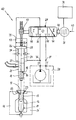
- the electrohydraulic drive device designated overall by 10 in FIG. 1, is intended for the control of feed and retraction movements of the blow mandrel 11 of a blow molding machine which is essentially represented by it and the drive device 10 and a blow mold 16, 16 ', with which hollow body 12, e.g. Plastic bottles can be produced which have in their neck area 13 - the calibration area - an external thread for screwing on a closure cap (not shown).
- the blow mandrel 11 starts from an upper end position, shown in FIG. 1, as a starting position, in which it is arranged at a clear, vertical distance from the blow mold opening 17, via intermediate positions shown in FIGS. 2a to 2c into the 2d, in FIG.
- a collar-shaped edge 23 of protruding material of the preform 14 is completely or largely sheared off from the calibrated bottle neck 13, so that it follows the extraction of the blow mandrel 11 from the blown hollow body 12 and the opening of the mold 16, 16 'can be tapped or knocked off without any significant effort.
- the drive device 10 includes a "standing" - with vertical course of its central longitudinal axis 24 - arranged, double-acting linear hydraulic cylinder 26 with one-sided downward protruding from the housing piston rod 27, on the lower free end of which the head 21 of the blow mandrel 11 is arranged, a pressure supply unit 28, only indicated schematically, and - for controlling the movement of the Blowing mandrel 11 - a follow-up control valve 28, which works with an electromechanically controllable setpoint specification for the possible positions of the piston 29 of the drive hydraulic cylinder 26 and thus also the blowing mandrel 11, as well as with mechanical actual position feedback, a stepping motor being used for setting the desired position value 31 is provided, which can be controlled by output signals from an electronic control unit 32 for controlling incremental changes in the piston positions.
- stepper motor instead of a stepper motor, another incrementally guided electric servo motor can also be used, i.e. also an AC or a DC motor which can be controlled to carry out incremental rotary movements of its rotor.
- the piston 29 of the hydraulic drive cylinder 26 delimits an upper drive pressure chamber 33 in a pressure-tight manner against a lower drive pressure chamber 34, the piston surface F 1 on which the piston 29 is acted upon by a pressure that can be coupled into the upper drive pressure chamber 33, for example 3 is up to 5 times, larger than the annular area F 2 on which the piston 29 by coupling pressure into the lower drive pressure chamber 34 of the drive hydraulic cylinder 26 can be acted upon.
- the lower drive pressure chamber 34 of the drive hydraulic cylinder - during operation of the drive device 10 - is permanently connected to the P high-pressure outlet 36 of the pressure supply unit 28, so that downward feed movements of the blow mandrel 11 by pressure coupling into the upper drive pressure chamber 33 and upward withdrawing movements of the blow mandrel 11 can be controlled by relieving the pressure in the upper drive pressure chamber 33 of the drive hydraulic cylinder 26.
- the overrun control valve is designed as a 3/3-way proportional valve, which has a blocking basic position 0, in which the upper drive pressure chamber 33 of the drive hydraulic cylinder is shut off both against the P supply connection 36 of the pressure supply unit 28 and against its T return connection 37 is and can be controlled by controlling the electric stepping motor 31 in alternative directions of rotation in alternative functional positions I and II, to which alternative directions of movement of the piston 29 - and the blow mandrel 11 - correspond.
- the overrun control valve 28 reaches its flow position II, which is alternative to the functional position I, in which the flow path 44 is released, and in which the control connection 39 of the upper drive pressure chamber 33 is via an now released flow path 46 of the overrun control valve 28 of the drive hydraulic cylinder is connected to the return connection 41 of the follow-up control valve and is blocked against the P supply connection 38 of the follow-up control valve 28, with the result that the blow mandrel 11 is driven to carry out an upward return stroke.
- the overrun control valve 28, for which training as a rotary slide valve is required, is designed, in accordance with its function as a proportional valve, that between actuation positions, the maximum deflections of its valve body in the sense of taking the alternative functional positions I and II and the flow cross sections of the flow paths 44 or 46 each have maximum values, and the locking position 0 the flow cross sections of these flow paths 44 and 46 vary monotonically between a maximum value and the value 0.
- the position feedback device of the overrun control valve shown as a rack and pinion gear 47, for which, for the purpose of explanation, a design as a rotary slide valve is required, the piston of which can be driven in rotation by means of the stepping motor 31, mediates in the directions of movement of the piston 29 of the drive which can be controlled thereby.
- Hydraulic cylinder 26 with the rotary deflections of the piston in the same direction rotations of a housing element of the overrun control valve 28, with the result that in a steady operating state of the drive device 10, given the equality between the actual position value and the desired position value, the overrun control valve 28 assumes its blocking position 0 and this also applies, apart from a follow-up error given by the control loop gain, if the actuation speed of the piston 29 of the drive hydraulic cylinder is controlled by a control pulse supplied by the frequency to the stepping motor 31 Setpoint corresponds to the speed of movement.
- the drive device 10 is operated as follows, reference being made to the diagram of FIG. 3 for explaining the movement sequence of the blowing mandrel 11, in which the time course of the position setpoint specification for the blowing mandrel is qualitative in solid lines 11 in units of the distance of the cutting edge 18 of the blow mandrel head 21 from its end position shown in FIG. 2d is shown and dashed - likewise qualitatively - the course over time of the actual position of this cutting edge 18.
- the blow mandrel is moved towards the blow mold 16, 16 ′ at rapid feed rate v 1 , the position setpoint specification developing in accordance with the first falling branch 48 of the setpoint curve 49 until a time t 1 2a corresponding position of the blow mandrel 11 is reached, in which it is still a clear distance from the plastic material and between the conically tapering blow mandrel end and the collar-shaped edge 23 emerging from the blow mold opening 17 of the plastic material - the "Tulip" - there is still an annular gap of notable diameter.
- a slower, downward feed rate is set in, as represented by the second falling branch 52 of the setpoint curve 49.
- the blow head 21 and the blow mandrel 11 come into contact with the neck region 13 of the plastic preform 14, as shown qualitatively by FIG. 2b, wherein this is increasingly displaced radially outwards and shaped grooves 53, which are provided for forming the bottle bottle thread, are increasingly filled with plastic.
- This slow feed speed which corresponds to approximately 1/5 of the rapid traverse speed, is controlled until the cutting edge 18 of the blow mandrel head comes into contact with the material of the collar-shaped edge 23 and begins to penetrate into it, as qualitatively represented by FIG. 2c, the Resistance against which the blow head has to be moved increases. From reaching this position, which may be the case at time t 3 , in order to achieve a sudden squeezing of the tulip 23, the feed speed of the blowing mandrel 11 is increased again to the value of the rapid traverse speed, as is the desired value by the third falling branch 54 Represents curve 49.
- this setpoint is initially as by the branch 54 running below the abscissa '
- the setpoint curve represents further reduced and only from time t 5 , as represented by the first rising branch 57 of the setpoint curve raised to the actually desired position setpoint, the contact of the cutting edge 18 with the conical edge surface 22 of the mold opening 17 corresponds.
- the time t 6 at which this setpoint control is reached can be tuned very precisely due to the control behavior of the follow-up control valve 28, so that the control can be designed by means of the electronic control unit 32 so that at time t 6 the position setpoint and actual position value are practically identical Blow pin position is given.
- the blowing mandrel 11 assumes this position shown in FIG. 2d
- the mold hollow body 12 is blown into its final shape until time t 7 .
- the mold hollow body 12 is raised hanging on the blow mandrel 11 at a moderate speed, as represented by the second rising branch 58 of the position-target value curve 49 until, for example, a takeover position is reached at time t 8 .
- the hollow mold body is removed from the blow mandrel using a mask and then, from time t 9, the free blow mandrel 11 is raised again to its starting position at rapid speed, which position was reached at time t 10 .
Landscapes
- Engineering & Computer Science (AREA)
- Manufacturing & Machinery (AREA)
- Mechanical Engineering (AREA)
- Blow-Moulding Or Thermoforming Of Plastics Or The Like (AREA)
Applications Claiming Priority (2)
| Application Number | Priority Date | Filing Date | Title |
|---|---|---|---|
| DE19537109 | 1995-10-05 | ||
| DE19537109A DE19537109C2 (de) | 1995-10-05 | 1995-10-05 | Verfahren zur Steuerung der Vorschub- und Rückzugsbewegungen des Blasdornes einer Blasformmaschine |
Publications (3)
| Publication Number | Publication Date |
|---|---|
| EP0767045A2 true EP0767045A2 (fr) | 1997-04-09 |
| EP0767045A3 EP0767045A3 (fr) | 1999-02-17 |
| EP0767045B1 EP0767045B1 (fr) | 2002-02-20 |
Family
ID=7774099
Family Applications (1)
| Application Number | Title | Priority Date | Filing Date |
|---|---|---|---|
| EP96115766A Expired - Lifetime EP0767045B1 (fr) | 1995-10-05 | 1996-10-02 | Dispositif d'entraínement électro-hydraulique pour un mandrin de soufflage d'une machine de moulage par soufflage |
Country Status (3)
| Country | Link |
|---|---|
| EP (1) | EP0767045B1 (fr) |
| AT (1) | ATE213454T1 (fr) |
| DE (2) | DE19537109C2 (fr) |
Cited By (4)
| Publication number | Priority date | Publication date | Assignee | Title |
|---|---|---|---|---|
| WO2004078456A1 (fr) * | 2003-03-04 | 2004-09-16 | Davis-Standard Corporation | Detendeur et controleur pour machine de soufflage et son procede |
| US7160099B2 (en) | 2003-09-02 | 2007-01-09 | Davis-Standard, Llc | Leakage-free feed roll assembly for an extruder machine |
| EP2505336A1 (fr) * | 2011-03-31 | 2012-10-03 | Hesta Blasformtechnik GmbH&Co. KG | Dispositif d'entraînement pour la canne de soufflage d'une machine de formage par soufflage |
| CN107160658A (zh) * | 2017-06-19 | 2017-09-15 | 江苏新美星包装机械股份有限公司 | 吹瓶机中的封口装置 |
Families Citing this family (2)
| Publication number | Priority date | Publication date | Assignee | Title |
|---|---|---|---|---|
| DE19829679A1 (de) * | 1998-07-03 | 2000-01-05 | Hartmann & Laemmle | Hydraulische Antriebseinrichtung für eine Widerstands-Schweißmaschine |
| DE102007008092A1 (de) | 2007-02-19 | 2008-08-21 | Robert Bosch Gmbh | Elektrohydraulische Antriebseinrichtung |
Family Cites Families (7)
| Publication number | Priority date | Publication date | Assignee | Title |
|---|---|---|---|---|
| DE1454970B2 (de) * | 1964-10-23 | 1972-06-15 | Gebruder Battenfeld, 5892 Meinerz hagen | Verfahren und vorrichtung zum herstellen von hohlkoerpern, wie flaschen od.dgl., aus thermoplastischem kunststoff |
| JPS5374569A (en) * | 1976-12-15 | 1978-07-03 | Kayaba Industry Co Ltd | Apparatus for compensating length of parison in hollow plastic molding machine |
| US4187070A (en) * | 1978-03-20 | 1980-02-05 | Roman Machine Co. | Blow molding machine |
| DE3642643A1 (de) * | 1986-12-13 | 1988-06-23 | Rexroth Mannesmann Gmbh | Schaltungsanordnung zum positionieren eines geschwindigkeitsveraenderlichen antriebes, insbesondere fuer eine kunststoffmaschine |
| JPH0238020A (ja) * | 1988-07-29 | 1990-02-07 | Hiroshi Sato | プラスチック成形機の電気的液圧制御装置と方法 |
| US5478229A (en) * | 1993-01-29 | 1995-12-26 | The Japan Steel Works, Ltd. | Apparatus for forming hollow article |
| DE4443194B4 (de) * | 1994-12-05 | 2004-08-05 | Hesta-Graham Gmbh & Co. Kg | Antriebseinrichtung für den Blasdorn einer Blasformmaschine |
-
1995
- 1995-10-05 DE DE19537109A patent/DE19537109C2/de not_active Expired - Fee Related
-
1996
- 1996-10-02 EP EP96115766A patent/EP0767045B1/fr not_active Expired - Lifetime
- 1996-10-02 AT AT96115766T patent/ATE213454T1/de not_active IP Right Cessation
- 1996-10-02 DE DE59608755T patent/DE59608755D1/de not_active Expired - Lifetime
Cited By (6)
| Publication number | Priority date | Publication date | Assignee | Title |
|---|---|---|---|---|
| WO2004078456A1 (fr) * | 2003-03-04 | 2004-09-16 | Davis-Standard Corporation | Detendeur et controleur pour machine de soufflage et son procede |
| US7179073B2 (en) | 2003-03-04 | 2007-02-20 | Davis-Standard, Llc | Pressure-reducing valve and a controller for a blow-molding machine and method thereof |
| US7160099B2 (en) | 2003-09-02 | 2007-01-09 | Davis-Standard, Llc | Leakage-free feed roll assembly for an extruder machine |
| EP2505336A1 (fr) * | 2011-03-31 | 2012-10-03 | Hesta Blasformtechnik GmbH&Co. KG | Dispositif d'entraînement pour la canne de soufflage d'une machine de formage par soufflage |
| DE102011015672B4 (de) | 2011-03-31 | 2021-10-07 | new HESTA blow moulding solutions GmbH & Co. KG | Antriebseinrichtung für den Blasdorn einer Blasformmaschine |
| CN107160658A (zh) * | 2017-06-19 | 2017-09-15 | 江苏新美星包装机械股份有限公司 | 吹瓶机中的封口装置 |
Also Published As
| Publication number | Publication date |
|---|---|
| DE19537109C2 (de) | 2003-04-24 |
| ATE213454T1 (de) | 2002-03-15 |
| EP0767045A3 (fr) | 1999-02-17 |
| DE19537109A1 (de) | 1997-04-10 |
| DE59608755D1 (de) | 2002-03-28 |
| EP0767045B1 (fr) | 2002-02-20 |
Similar Documents
| Publication | Publication Date | Title |
|---|---|---|
| DE2603891C3 (de) | Antrieb zum Bewegen eines Einspritzkolbens einer Druckgießmaschine | |
| DE2544609C3 (de) | Einrichtung zum Beeinflussen der Länge eines Vorformlings aus thermoplastischem Kunststoff | |
| EP0508277B1 (fr) | Dispositif d'entraînement pour le déplacement et/ou la force de positionnement pour machines à mouler par injection | |
| DE1147750B (de) | Formschliessvorrichtung, insbesondere fuer thermoplastische Kunststoffe verarbeitende Spritzgussmaschinen | |
| DE102019125604B4 (de) | Schließeinheit für eine Formgebungsmaschine, Formgebungsmaschine und Verfahren zum Öffnen oder Schließen einer Schließeinheit für eine Formgebungsmaschine | |
| DE102019105681B4 (de) | Formgebungsmaschine und Verfahren zum Betreiben einer Formgebungsmaschine | |
| DE10316199B4 (de) | Verfahren und Vorrichtung zum Formschließen bei einer Spritzgießmaschine oder dergleichen | |
| DE112016000837T5 (de) | Form-Klemm-Vorrichtung, Urformvorrichtung und Urformverfahren | |
| DE4325180A1 (de) | Klemmeinheit für eine Spritzmaschine und Verfahren zum Betrieb derselben | |
| EP0740995A2 (fr) | Procédé et appareil pour la fermeture de l'outil d'une machine à fabrication de plastique | |
| EP0767045B1 (fr) | Dispositif d'entraínement électro-hydraulique pour un mandrin de soufflage d'une machine de moulage par soufflage | |
| EP1958754A1 (fr) | Dispositif d'entraînement, en particulier pour un composant mobile sur une machine de moulage par injection de matière plastique ou une machine de formage par soufflage | |
| DE4310310A1 (de) | Einpreßaggregat | |
| EP1389161B1 (fr) | Dispositif d'entrainement servant notamment a entrainer une partie mobile de l'unite de fermeture ou de l'unite d'injection d'une presse d'injection de matieres plastiques | |
| EP1814708A1 (fr) | Dispositif de plastification et d'injection | |
| EP0139099B1 (fr) | Groupe de fermeture d'une presse à mouler par injection | |
| CH681244A5 (fr) | ||
| EP4458547A1 (fr) | Unité de fermeture de moule et procédé de fonctionnement d'une unité de fermeture de moule d'une machine de traitement de matières plastiques | |
| DE19848681C2 (de) | Auswerfer für eine Spritzgießmaschine | |
| DE717176C (de) | Regeleinrichtung fuer Brennkraftmaschinen, die einen Stromerzeuger zur Speisung eines oder mehrerer Elektromotoren antreiben | |
| DE19819759A1 (de) | Vorrichtung zur Betätigung eines Einspritzelements | |
| WO2013013925A2 (fr) | Tête d'injection et éjecteur d'un dispositif d'injection | |
| DE909332C (de) | Einrichtung zur Vermeidung einer Einschnuerung in einem Mantel oder in einem Rohr bei der Herstellung dieses Mantels oder Rohres mittels einer Strangpresse | |
| AT372039B (de) | Vorrichtung zum herstellen von hohlkoerpern aus thermoplastischem kunststoff | |
| DE1503246C3 (de) | Reguliereinrichtung für eine Pelton-Turbine |
Legal Events
| Date | Code | Title | Description |
|---|---|---|---|
| PUAI | Public reference made under article 153(3) epc to a published international application that has entered the european phase |
Free format text: ORIGINAL CODE: 0009012 |
|
| AK | Designated contracting states |
Kind code of ref document: A2 Designated state(s): AT CH DE FR IT LI |
|
| PUAL | Search report despatched |
Free format text: ORIGINAL CODE: 0009013 |
|
| AK | Designated contracting states |
Kind code of ref document: A3 Designated state(s): AT CH DE FR IT LI |
|
| 17P | Request for examination filed |
Effective date: 19990618 |
|
| RAP1 | Party data changed (applicant data changed or rights of an application transferred) |
Owner name: HESTA-GRAHAM GMBH & CO. KG |
|
| 17Q | First examination report despatched |
Effective date: 20000928 |
|
| GRAG | Despatch of communication of intention to grant |
Free format text: ORIGINAL CODE: EPIDOS AGRA |
|
| GRAG | Despatch of communication of intention to grant |
Free format text: ORIGINAL CODE: EPIDOS AGRA |
|
| GRAH | Despatch of communication of intention to grant a patent |
Free format text: ORIGINAL CODE: EPIDOS IGRA |
|
| GRAH | Despatch of communication of intention to grant a patent |
Free format text: ORIGINAL CODE: EPIDOS IGRA |
|
| GRAA | (expected) grant |
Free format text: ORIGINAL CODE: 0009210 |
|
| AK | Designated contracting states |
Kind code of ref document: B1 Designated state(s): AT CH DE FR IT LI |
|
| REF | Corresponds to: |
Ref document number: 213454 Country of ref document: AT Date of ref document: 20020315 Kind code of ref document: T |
|
| REG | Reference to a national code |
Ref country code: CH Ref legal event code: EP |
|
| REF | Corresponds to: |
Ref document number: 59608755 Country of ref document: DE Date of ref document: 20020328 |
|
| ET | Fr: translation filed | ||
| PLBE | No opposition filed within time limit |
Free format text: ORIGINAL CODE: 0009261 |
|
| STAA | Information on the status of an ep patent application or granted ep patent |
Free format text: STATUS: NO OPPOSITION FILED WITHIN TIME LIMIT |
|
| 26N | No opposition filed |
Effective date: 20021121 |
|
| PGFP | Annual fee paid to national office [announced via postgrant information from national office to epo] |
Ref country code: AT Payment date: 20061207 Year of fee payment: 11 |
|
| PGFP | Annual fee paid to national office [announced via postgrant information from national office to epo] |
Ref country code: CH Payment date: 20061215 Year of fee payment: 11 |
|
| PGFP | Annual fee paid to national office [announced via postgrant information from national office to epo] |
Ref country code: IT Payment date: 20071023 Year of fee payment: 12 |
|
| REG | Reference to a national code |
Ref country code: CH Ref legal event code: PL |
|
| PG25 | Lapsed in a contracting state [announced via postgrant information from national office to epo] |
Ref country code: LI Free format text: LAPSE BECAUSE OF NON-PAYMENT OF DUE FEES Effective date: 20071031 Ref country code: CH Free format text: LAPSE BECAUSE OF NON-PAYMENT OF DUE FEES Effective date: 20071031 |
|
| PG25 | Lapsed in a contracting state [announced via postgrant information from national office to epo] |
Ref country code: AT Free format text: LAPSE BECAUSE OF NON-PAYMENT OF DUE FEES Effective date: 20071002 |
|
| REG | Reference to a national code |
Ref country code: FR Ref legal event code: TP Ref country code: FR Ref legal event code: CD Ref country code: FR Ref legal event code: CA |
|
| PG25 | Lapsed in a contracting state [announced via postgrant information from national office to epo] |
Ref country code: IT Free format text: LAPSE BECAUSE OF NON-PAYMENT OF DUE FEES Effective date: 20081002 |
|
| PGFP | Annual fee paid to national office [announced via postgrant information from national office to epo] |
Ref country code: FR Payment date: 20101104 Year of fee payment: 15 |
|
| PGFP | Annual fee paid to national office [announced via postgrant information from national office to epo] |
Ref country code: DE Payment date: 20101022 Year of fee payment: 15 |
|
| REG | Reference to a national code |
Ref country code: FR Ref legal event code: ST Effective date: 20120629 |
|
| PG25 | Lapsed in a contracting state [announced via postgrant information from national office to epo] |
Ref country code: DE Free format text: LAPSE BECAUSE OF NON-PAYMENT OF DUE FEES Effective date: 20120501 |
|
| REG | Reference to a national code |
Ref country code: DE Ref legal event code: R119 Ref document number: 59608755 Country of ref document: DE Effective date: 20120501 |
|
| PG25 | Lapsed in a contracting state [announced via postgrant information from national office to epo] |
Ref country code: FR Free format text: LAPSE BECAUSE OF NON-PAYMENT OF DUE FEES Effective date: 20111102 |