EP0767233A1 - Verfahren zur Lagerung bei niedriger Temperatur von geschichtetem gekühltem Wasser - Google Patents
Verfahren zur Lagerung bei niedriger Temperatur von geschichtetem gekühltem Wasser Download PDFInfo
- Publication number
- EP0767233A1 EP0767233A1 EP95650040A EP95650040A EP0767233A1 EP 0767233 A1 EP0767233 A1 EP 0767233A1 EP 95650040 A EP95650040 A EP 95650040A EP 95650040 A EP95650040 A EP 95650040A EP 0767233 A1 EP0767233 A1 EP 0767233A1
- Authority
- EP
- European Patent Office
- Prior art keywords
- solution
- water
- sodium
- sodium nitrite
- chilled water
- Prior art date
- Legal status (The legal status is an assumption and is not a legal conclusion. Google has not performed a legal analysis and makes no representation as to the accuracy of the status listed.)
- Granted
Links
Images


Classifications
-
- F—MECHANICAL ENGINEERING; LIGHTING; HEATING; WEAPONS; BLASTING
- F25—REFRIGERATION OR COOLING; COMBINED HEATING AND REFRIGERATION SYSTEMS; HEAT PUMP SYSTEMS; MANUFACTURE OR STORAGE OF ICE; LIQUEFACTION SOLIDIFICATION OF GASES
- F25D—REFRIGERATORS; COLD ROOMS; ICE-BOXES; COOLING OR FREEZING APPARATUS NOT OTHERWISE PROVIDED FOR
- F25D16/00—Devices using a combination of a cooling mode associated with refrigerating machinery with a cooling mode not associated with refrigerating machinery
-
- C—CHEMISTRY; METALLURGY
- C09—DYES; PAINTS; POLISHES; NATURAL RESINS; ADHESIVES; COMPOSITIONS NOT OTHERWISE PROVIDED FOR; APPLICATIONS OF MATERIALS NOT OTHERWISE PROVIDED FOR
- C09K—MATERIALS FOR MISCELLANEOUS APPLICATIONS, NOT PROVIDED FOR ELSEWHERE
- C09K5/00—Heat-transfer, heat-exchange or heat-storage materials, e.g. refrigerants; Materials for the production of heat or cold by chemical reactions other than by combustion
- C09K5/02—Materials undergoing a change of physical state when used
- C09K5/06—Materials undergoing a change of physical state when used the change of state being from liquid to solid or vice versa
-
- C—CHEMISTRY; METALLURGY
- C09—DYES; PAINTS; POLISHES; NATURAL RESINS; ADHESIVES; COMPOSITIONS NOT OTHERWISE PROVIDED FOR; APPLICATIONS OF MATERIALS NOT OTHERWISE PROVIDED FOR
- C09K—MATERIALS FOR MISCELLANEOUS APPLICATIONS, NOT PROVIDED FOR ELSEWHERE
- C09K5/00—Heat-transfer, heat-exchange or heat-storage materials, e.g. refrigerants; Materials for the production of heat or cold by chemical reactions other than by combustion
- C09K5/02—Materials undergoing a change of physical state when used
- C09K5/06—Materials undergoing a change of physical state when used the change of state being from liquid to solid or vice versa
- C09K5/063—Materials absorbing or liberating heat during crystallisation; Heat storage materials
-
- F—MECHANICAL ENGINEERING; LIGHTING; HEATING; WEAPONS; BLASTING
- F28—HEAT EXCHANGE IN GENERAL
- F28D—HEAT-EXCHANGE APPARATUS, NOT PROVIDED FOR IN ANOTHER SUBCLASS, IN WHICH THE HEAT-EXCHANGE MEDIA DO NOT COME INTO DIRECT CONTACT
- F28D20/00—Heat storage plants or apparatus in general; Regenerative heat-exchange apparatus not covered by groups F28D17/00 or F28D19/00
- F28D20/0034—Heat storage plants or apparatus in general; Regenerative heat-exchange apparatus not covered by groups F28D17/00 or F28D19/00 using liquid heat storage material
- F28D20/0039—Heat storage plants or apparatus in general; Regenerative heat-exchange apparatus not covered by groups F28D17/00 or F28D19/00 using liquid heat storage material with stratification of the heat storage material
-
- F—MECHANICAL ENGINEERING; LIGHTING; HEATING; WEAPONS; BLASTING
- F28—HEAT EXCHANGE IN GENERAL
- F28D—HEAT-EXCHANGE APPARATUS, NOT PROVIDED FOR IN ANOTHER SUBCLASS, IN WHICH THE HEAT-EXCHANGE MEDIA DO NOT COME INTO DIRECT CONTACT
- F28D20/00—Heat storage plants or apparatus in general; Regenerative heat-exchange apparatus not covered by groups F28D17/00 or F28D19/00
- F28D2020/0065—Details, e.g. particular heat storage tanks, auxiliary members within tanks
- F28D2020/0069—Distributing arrangements; Fluid deflecting means
-
- Y—GENERAL TAGGING OF NEW TECHNOLOGICAL DEVELOPMENTS; GENERAL TAGGING OF CROSS-SECTIONAL TECHNOLOGIES SPANNING OVER SEVERAL SECTIONS OF THE IPC; TECHNICAL SUBJECTS COVERED BY FORMER USPC CROSS-REFERENCE ART COLLECTIONS [XRACs] AND DIGESTS
- Y02—TECHNOLOGIES OR APPLICATIONS FOR MITIGATION OR ADAPTATION AGAINST CLIMATE CHANGE
- Y02E—REDUCTION OF GREENHOUSE GAS [GHG] EMISSIONS, RELATED TO ENERGY GENERATION, TRANSMISSION OR DISTRIBUTION
- Y02E60/00—Enabling technologies; Technologies with a potential or indirect contribution to GHG emissions mitigation
- Y02E60/14—Thermal energy storage
Definitions
- This invention relates generally to a method for thermal energy storage and, particularly, to a method for storing thermal energy using stratified chilled water.
- thermal energy storage might be found in a district cooling system for providing cooling for a large number of buildings from a single source. It is known in such a district cooling system that it is possible to utilize equipment that has less cooling capacity than the peak demand requires by using thermal energy storage. More specifically, the chilling equipment is operated at night during a minimal demand period and chilled water is stored in a large thermal storage tank. Then, when the demand increases during the day the chilled water is drawn off from the tank to improve the ability of the cooling equipment to provide the required cooling. As an example of the scale of such a district cooling system it is possible to use cooling equipment that has a 6,000 ton capacity to meet a cooling requirement of 11,000 tons by using a thermal storage tank holding around three million gallons of water.
- thermal storage tank is always full, so that as cooled water is drawn off from the bottom of the tank the warmer water is returned at the top.
- the range of temperatures in such a tank is typically from 5.5°C (42°F) to 15.55°C (60°F) and between these temperatures the respective specific gravities of water increases steadily as the temperature drops resulting in gravity separation such as there would be in a conventional hot water tank, for example.
- thermal storage tanks usually have some sort of non-mixing inlet/outlet system so that the cooled outlet water is not mixed with the warm inlet water.
- the thermal storage tank will typically have a layer of chilled water at around 5.5°C (42°F) at the bottom with a layer of warm water of up to 15.55°C (60°F) on top of the chilled water.
- brines such as calcium chloride, sodium chloride, or glycol
- brine solutions or glycol solutions have been used for many years, they each have particular problems which require either expensive or presently unacceptable remedies.
- brine solutions are corrosive and require the use of a corrosion inhibitor.
- the most commonly used corrosion inhibitor has been sodium chromate.
- sodium chromate is an environmentally unacceptable chemical and is, therefore, not available for use.
- Another object of this invention is to provide a method of low-temperature stratified chilled water storage in which the freezing point of the water is depressed without destroying the ability to achieve stratification of the different temperature liquids in the thermal storage tank.
- a method of achieving low-temperature stratified chilled water storage involves adding aqueous solutions of sodium nitrite and sodium nitrate separately or in combination to the water forming the thermal mass sink being returned in the thermal storage tank. Utilizing sodium nitrite and sodium nitrate alone or in combination in accordance with the present invention depresses the solution freezing point and permits a straight line density temperature curve of the overall system, resulting in stratified storage of the thermal mass at temperatures below 4.4°C (40°F) and, more specifically, 4.1°C (39.4°F).
- nitrite/nitrate solution concentrations can be utilized in practicing the present invention.
- the solution concentrations can range from less than 3% up to 25% and still obtain the thermal savings benefits while remaining economically advantageous.
- Fig. 1 represents a typical application for air-conditioning or process cooling in which a cooling plant 10 provides the necessary chilled water to a cooling distribution network 12 with the thermal storage being provided by a large water tank 14.
- the cooling plant 10 may relate to a district air-conditioning system or to a process cooling application and in both cases the thermal storage takes place in the water tank 14.
- Fig. 2 represents a typical water tank 20 used in a system such as that of Fig. 1.
- this tank may be as big as 127 feet in diameter and 90 feet high. It is in this large volume of cooling liquid that the stratification must be maintained, so that the storage of both warm and chilled water in the same tank can be accomplished.
- such a storage tank 20 typically has a nonmixing inlet and outlet system to prevent agitation and mixing of the cooled water and warm water as it is introduced into and drawn out of the tank.
- a nonmixing inlet and outlet system to prevent agitation and mixing of the cooled water and warm water as it is introduced into and drawn out of the tank.
- Such nonmixing can be accomplished using radial diffuser plates at the inlet/outlet at the top and bottom of the tank, shown respectively at 22 and 24.
- Such nonmixing can also be accomplished using a two-pipe baffle system at each inlet and outlet. In such baffle system two pipes, not shown, are concentrically arranged with the apertures in the pipes being offset relative to each other.
- thermocline is the area of mixed temperature water between the 5.5°C (42°F) chilled water and the 15.55°C (60°F) return water. It will be understood that any mixing, as represented by a very thick thermocline layer, will reduce the amount of chilled water that can be stored at night for delivery to buildings at the required temperature during the day. This interface layer or band will move up and down in the tank as chilled water is taken from or added to the tank.
- Maintaining this stratification is an important feature of the present invention and relates to the separation of liquids at different densities in a container when not exposed to turbulence or mixing due to fluid flow.
- the present invention teaches to take steps to change the density of the solution in proportion to the temperature change. Referring to Fig. 4, it is seen that the colder the solution, the higher the density. For example, assume that the tank 20 is full of solution at 12.22°C (54°F) with a density of 1.048 x 10 3 kg.m- 3 (8.75 lbs/gal) and chilled solution is introduced through inlet diffuser 24 at -1.11°C (30°F) with a density of 1.052 x 10 3 kg.m -3 (8.781bs/gal).
- the -1.11°C (30°F) solution will form a layer at the bottom of the tank 20 and will remain separated indefinitely from the 12.22°C (54°F) solution, so long as there is no change in solution layer temperature.
- the above-described interface band or thermocline will exist between the two solution layers.
- the addition of sodium nitrite and sodium nitrate alone or in combination will permit stratified storage of the thermal mass below the 4.4°C (40.0°F) limit permitted when utilizing water alone.
- a 7% solution of sodium nitrite and sodium nitrate in a 2 to 1 ratio is provided, however, the solution concentration can range from below 3% to at least 25%.
- 3%, 15% and 25% solutions of sodium nitrite and sodium nitrate in a 2 to 1 ratio are provided.
- the use of the sodium nitrite/sodium nitrate solution permits storage of the chilled solution at lower temperatures than with only water.
- the minimum temperature at which pure water can be stored in a stratification mode is 3.88°C (39°F).
- the density of water decreases, thus water colder than 3.88°C (39°F) will rise in the tank and the desired stratification will not take place.
- the present invention teaches that even when using concentrations for thermal storage of less than 5%, but not less than 3%, microbiological growth does not occur at these concentrations and, in fact, the solution has been found to be microbicidal.
- a further advantage in utilizing sodium nitrite to lower the temperature of the chilled water is that sodium nitrite is readily oxidized to nitrate, either biologically or by chlorination. This means that such nitrate can be removed from the waste water by natural biological action or by aquatic vegetation.
- the present invention teaches to depress the freezing point of the solution to permit cooling below 0°C (32°F) and also to produce a temperature/density gradient to allow the production of a stratified thermal mass.
- Fig. 3 represents a straight line temperature/density curve attainable in keeping with the present invention by using a 3% sodium nitrite/sodium nitrate solution in a 2 to 1 ratio.
- Fig. 4 represents a straight line temperature/density curve attainable in keeping with the present invention by using a 7% sodium nitrite/sodium nitrate solution in a 2 to 1 ratio.
- Fig. 3 represents a straight line temperature/density curve attainable in keeping with the present invention by using a 3% sodium nitrite/sodium nitrate solution in a 2 to 1 ratio.
- Fig. 4 represents a straight line temperature/density curve attainable in keeping with the present invention by using a 7% sodium nitrite/sodium nitrate
- Fig. 5 represents a straight line temperature/density curve attainable in keeping with the present invention by using a 15% sodium nitrite/sodium nitrate solution in a 2 to 1 ratio.
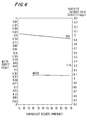
- Fig. 6 represents a straight line temperature/density curve attainable in keeping with the present invention by using a 25% sodium nitrite/nitrate solution in a 2 to 1 ratio.
- a further advantage obtained by using sodium nitrite/sodium nitrate according to the present invention is the provision of corrosion inhibition for the metals employed in the cooling system.
- chloride and sulphate salts might be generally less expensive than sodium nitrite/sodium nitrate, they are corrosive and require the addition of corrosion inhibitors.
- the most effective and only commercially available chloride corrosion inhibitor is chromate, however, because of environmental restrictions chromate can not be used.
- the thermal storage operates at a chilled water temperature of -1.1°C (30°F) and in order to provide freeze protection in the system and equipment, a solution strength of 3% sodium nitrite and sodium nitrate in a 2 to 1 ratio was prepared that has a freezing point of -1.6° (29.2°F). This results in an approximate straight line temperature density curve over the system operating temperature range of -1.1°C (30°F) to 13.3°C (56°F).
- Tests relating to the use of a corrosion coupon and the linear polarization resistance technique showed the 7% solution was not only non-corrosive to mild steel but also creates corrosion inhibitors, and is only moderately corrosive to copper and copper alloys. In this example, a 5.5 ppm of tolyltriazole was added and this sharply decreased the corrosion rate for copper and brass.
- the thermal storage operates at a chilled water temperature of -1.1°C (30°F) and in order to provide freeze protection in the system and equipment, a solution strength of 7% sodium nitrite and sodium nitrate in a 2 to 1 ratio was prepared that has a freezing point of -3.75°C (25.25°F). This results in an approximate straight line temperature density curve over the system operating temperature range of -1.1°C (30°F) to 13.3°C (56°F).
- the thermal storage operates at a chilled water temperature of -1.1°C (30°F) and in order to provide freeze protection in the system and equipment, a solution strength of 15% sodium nitrite and sodium nitrate in a 2 to 1 ratio was prepared that has a freezing point of -7.5°C (18.5°F). This results in an approximate straight line temperature density curve over the system operating temperature range of -1.1°C (30°F) to 13.3°C (56°F).
- the thermal storage operates at a chilled water temperature of -1.1°C (30°F) and in order to provide freeze protection in the system and equipment, a solution strength of 25% sodium nitrite and sodium nitrate in a 2 to 1 ratio was prepared that has a freezing point of -13.2°C (8.3°F). This results in an approximate straight line temperature density curve over the system operating temperature range of -1.1°C (30°F) to 13.3°C (56°F).
- the solutions of the sodium nitrite and sodium nitrate mentioned above were tested for microbial activity using an inoculation procedure on the test solution and a control sample of tap water. The results showed that the nitrite/nitrate solutions of 3% concentration or more are inhibitory or microbicidal to microbiological growth. At concentrations of less than 3%, the nitrite/nitrate solutions are no longer microbicidal.
Landscapes
- Engineering & Computer Science (AREA)
- Chemical & Material Sciences (AREA)
- Thermal Sciences (AREA)
- Physics & Mathematics (AREA)
- Combustion & Propulsion (AREA)
- Materials Engineering (AREA)
- Chemical Kinetics & Catalysis (AREA)
- Organic Chemistry (AREA)
- Mechanical Engineering (AREA)
- General Engineering & Computer Science (AREA)
- Other Air-Conditioning Systems (AREA)
- Filling Or Discharging Of Gas Storage Vessels (AREA)
- Agricultural Chemicals And Associated Chemicals (AREA)
- Management, Administration, Business Operations System, And Electronic Commerce (AREA)
- Air Conditioning Control Device (AREA)
Applications Claiming Priority (2)
| Application Number | Priority Date | Filing Date | Title |
|---|---|---|---|
| US538080 | 1983-10-03 | ||
| US08/538,080 US5655377A (en) | 1994-06-16 | 1995-10-02 | Method of low-temperature stratified chilled water storage |
Publications (2)
| Publication Number | Publication Date |
|---|---|
| EP0767233A1 true EP0767233A1 (de) | 1997-04-09 |
| EP0767233B1 EP0767233B1 (de) | 2000-07-19 |
Family
ID=24145399
Family Applications (1)
| Application Number | Title | Priority Date | Filing Date |
|---|---|---|---|
| EP95650040A Expired - Lifetime EP0767233B1 (de) | 1995-10-02 | 1995-11-13 | Verfahren zur Lagerung bei niedriger Temperatur von geschichtetem gekühltem Wasser |
Country Status (12)
| Country | Link |
|---|---|
| US (1) | US5655377A (de) |
| EP (1) | EP0767233B1 (de) |
| AR (1) | AR000124A1 (de) |
| BR (1) | BR9505165A (de) |
| CA (1) | CA2162769C (de) |
| CR (1) | CR5212A (de) |
| DE (1) | DE69518079T2 (de) |
| ES (1) | ES2152373T3 (de) |
| MA (1) | MA23981A1 (de) |
| MX (1) | MX9504743A (de) |
| MY (1) | MY113736A (de) |
| WO (1) | WO1997013105A1 (de) |
Cited By (1)
| Publication number | Priority date | Publication date | Assignee | Title |
|---|---|---|---|---|
| AU2012249235B1 (en) * | 2012-11-14 | 2013-06-20 | Mesh Corporation Pty Ltd | District Cooling System and Thermal Energy Storage Tank System Layout |
Families Citing this family (8)
| Publication number | Priority date | Publication date | Assignee | Title |
|---|---|---|---|---|
| US6848267B2 (en) * | 2002-07-26 | 2005-02-01 | Tas, Ltd. | Packaged chilling systems for building air conditioning and process cooling |
| US6408609B1 (en) | 2000-06-09 | 2002-06-25 | Chicago Bridge & Iron Company | Method and apparatus for enhancing power output and efficiency of combustion turbines |
| US7856843B2 (en) * | 2006-04-05 | 2010-12-28 | Enis Ben M | Thermal energy storage system using compressed air energy and/or chilled water from desalination processes |
| US8863547B2 (en) * | 2006-04-05 | 2014-10-21 | Ben M. Enis | Desalination method and system using compressed air energy systems |
| US8695360B2 (en) * | 2006-04-05 | 2014-04-15 | Ben M. Enis | Desalination method and system using compressed air energy systems |
| US8523643B1 (en) * | 2007-06-14 | 2013-09-03 | Switch Communications Group LLC | Electronic equipment data center or co-location facility designs and methods of making and using the same |
| US10247458B2 (en) | 2013-08-21 | 2019-04-02 | Carrier Corporation | Chilled water system efficiency improvement |
| US9803126B1 (en) | 2016-08-23 | 2017-10-31 | H-O-H Water Technology, Inc. | Method of low-temperature liquid containment and transport |
Citations (6)
| Publication number | Priority date | Publication date | Assignee | Title |
|---|---|---|---|---|
| FR2360048A1 (fr) * | 1976-07-30 | 1978-02-24 | Crede Helfried | Procede pour la captation d'energie, notamment de chaleur de chauffage d'apres le principe de la pompe de chaleur |
| EP0008487A1 (de) * | 1978-04-30 | 1980-03-05 | Joseph Menachem Wirguin | Einrichtung und Verfahren zur Speicherung thermischer Energie in einem Teich, der eine gesättigte wässerige Salzlösung enthält |
| US4254635A (en) * | 1978-01-06 | 1981-03-10 | Laszlo Simon | Installation for the storage of continuously generated coldness and for the intermittent emission of at least a portion of the stored cold |
| US4596120A (en) * | 1983-12-08 | 1986-06-24 | Chicago Bridge & Iron Company | Apparatus and method for cold aqueous liquid and/or ice production, storage and use for cooling and refrigeration |
| US5065598A (en) * | 1989-09-05 | 1991-11-19 | Mitsubishi Denki Kabushiki Kaisha | Ice thermal storage apparatus |
| US5465585A (en) * | 1994-06-16 | 1995-11-14 | Trigen Energy Corporation | Method of low-temperature stratified chilled water storage |
Family Cites Families (5)
| Publication number | Priority date | Publication date | Assignee | Title |
|---|---|---|---|---|
| US4109702A (en) * | 1976-08-06 | 1978-08-29 | Greene Norman Donald | Energy storage and retrieval as heat |
| US4446910A (en) * | 1980-05-22 | 1984-05-08 | General Electric Company | Two-phase thermal storage means and method |
| US4595516A (en) * | 1983-12-05 | 1986-06-17 | Matsushita Electric Industrial Co., Ltd. | Heat storage material |
| US4821794A (en) * | 1988-04-04 | 1989-04-18 | Thermal Energy Storage, Inc. | Clathrate thermal storage system |
| US5348080A (en) * | 1990-12-19 | 1994-09-20 | Tokyo Electric Power Company | Latent heat storage apparatus and latent heat storage solution therefor |
-
1995
- 1995-10-02 US US08/538,080 patent/US5655377A/en not_active Expired - Lifetime
- 1995-11-13 MY MYPI95003436A patent/MY113736A/en unknown
- 1995-11-13 BR BR9505165A patent/BR9505165A/pt not_active IP Right Cessation
- 1995-11-13 ES ES95650040T patent/ES2152373T3/es not_active Expired - Lifetime
- 1995-11-13 MX MX9504743A patent/MX9504743A/es not_active IP Right Cessation
- 1995-11-13 WO PCT/US1995/014656 patent/WO1997013105A1/en not_active Ceased
- 1995-11-13 DE DE69518079T patent/DE69518079T2/de not_active Expired - Fee Related
- 1995-11-13 AR AR33421795A patent/AR000124A1/es unknown
- 1995-11-13 EP EP95650040A patent/EP0767233B1/de not_active Expired - Lifetime
- 1995-11-14 CA CA002162769A patent/CA2162769C/en not_active Expired - Fee Related
- 1995-11-21 CR CR5212A patent/CR5212A/es unknown
-
1996
- 1996-10-01 MA MA24361A patent/MA23981A1/fr unknown
Patent Citations (6)
| Publication number | Priority date | Publication date | Assignee | Title |
|---|---|---|---|---|
| FR2360048A1 (fr) * | 1976-07-30 | 1978-02-24 | Crede Helfried | Procede pour la captation d'energie, notamment de chaleur de chauffage d'apres le principe de la pompe de chaleur |
| US4254635A (en) * | 1978-01-06 | 1981-03-10 | Laszlo Simon | Installation for the storage of continuously generated coldness and for the intermittent emission of at least a portion of the stored cold |
| EP0008487A1 (de) * | 1978-04-30 | 1980-03-05 | Joseph Menachem Wirguin | Einrichtung und Verfahren zur Speicherung thermischer Energie in einem Teich, der eine gesättigte wässerige Salzlösung enthält |
| US4596120A (en) * | 1983-12-08 | 1986-06-24 | Chicago Bridge & Iron Company | Apparatus and method for cold aqueous liquid and/or ice production, storage and use for cooling and refrigeration |
| US5065598A (en) * | 1989-09-05 | 1991-11-19 | Mitsubishi Denki Kabushiki Kaisha | Ice thermal storage apparatus |
| US5465585A (en) * | 1994-06-16 | 1995-11-14 | Trigen Energy Corporation | Method of low-temperature stratified chilled water storage |
Cited By (1)
| Publication number | Priority date | Publication date | Assignee | Title |
|---|---|---|---|---|
| AU2012249235B1 (en) * | 2012-11-14 | 2013-06-20 | Mesh Corporation Pty Ltd | District Cooling System and Thermal Energy Storage Tank System Layout |
Also Published As
| Publication number | Publication date |
|---|---|
| EP0767233B1 (de) | 2000-07-19 |
| ES2152373T3 (es) | 2001-02-01 |
| HK1014021A1 (en) | 1999-09-17 |
| CA2162769A1 (en) | 1997-04-03 |
| MY113736A (en) | 2002-05-31 |
| AR000124A1 (es) | 1997-05-21 |
| DE69518079D1 (de) | 2000-08-24 |
| BR9505165A (pt) | 1997-10-21 |
| WO1997013105A1 (en) | 1997-04-10 |
| CR5212A (es) | 1996-07-02 |
| CA2162769C (en) | 1999-07-27 |
| US5655377A (en) | 1997-08-12 |
| MX9504743A (es) | 1997-04-30 |
| MA23981A1 (fr) | 1997-07-01 |
| DE69518079T2 (de) | 2001-03-29 |
Similar Documents
| Publication | Publication Date | Title |
|---|---|---|
| US5465585A (en) | Method of low-temperature stratified chilled water storage | |
| US5065598A (en) | Ice thermal storage apparatus | |
| EP0767233B1 (de) | Verfahren zur Lagerung bei niedriger Temperatur von geschichtetem gekühltem Wasser | |
| EP1235046B1 (de) | Wärmespeichermaterial mit benutzung einer vorrichtung zur wärme- und hydratspeicherung und herstellungsverfahren des wärmespeichermaterials | |
| CA2318258C (en) | Frost resistant heating/cooling fluid | |
| JPS61500036A (ja) | 加圧式氷貯蔵冷水装置 | |
| Butler et al. | Some important aspects of corrosion in central heating systems | |
| HK1014021B (en) | Method of low-temperature stratified chilled water storage | |
| JP2004331935A (ja) | 冷熱輸送媒体 | |
| JP4645187B2 (ja) | 冷熱輸送媒体 | |
| Wild | Chilling Maple Sap | |
| Fang et al. | Analysis of the optimization on application of seawater slurry ice in coastal areas | |
| Hettler Jr | A filter and chiller for an open seawater system | |
| Jacobson et al. | Scale and Corrosion Parameters at a Geothermal Loop Experimental Facility | |
| JPH0792307B2 (ja) | 氷蓄熱装置 | |
| Eng et al. | Handbook on indirect refrigeration and heat pump systems | |
| Memet et al. | Romanian Reefer Trade Face to Face with Efficiency and Environment | |
| EP1543284A1 (de) | Ein kühlsystem und ein verfahren zur nutzung eines kühlsystems | |
| SU1620792A1 (ru) | Аккумул тор холода | |
| AU611669B2 (en) | Ice building, chilled water system and method | |
| Slesarenko et al. | The account of heat exchange features when modelling scale formation at distillation plants | |
| Lin | SCALE REDUCTION IN DESALINATION BY MODIFICATION OF CALCIUM-SULFATE TRANSIENT SOLUBILITY GRADIENT | |
| Knudsen et al. | The Effect of Corrosion Inhibitors on the Fouling Characteristics of Cooling Tower Water | |
| Andrepont | Applications of Low Temperature Fluid (LTF) in Thermally Stratified Thermally Stratified Thermal Energy Energy Storage (TES). | |
| Curcio et al. | Pool boiling of enhanced heat transfer surfaces in refrigerant-oil mixtures and aqueous calcium sulfate solutions |
Legal Events
| Date | Code | Title | Description |
|---|---|---|---|
| PUAI | Public reference made under article 153(3) epc to a published international application that has entered the european phase |
Free format text: ORIGINAL CODE: 0009012 |
|
| AK | Designated contracting states |
Kind code of ref document: A1 Designated state(s): BE DE ES FR GB IT |
|
| 17P | Request for examination filed |
Effective date: 19970319 |
|
| GRAG | Despatch of communication of intention to grant |
Free format text: ORIGINAL CODE: EPIDOS AGRA |
|
| 17Q | First examination report despatched |
Effective date: 19991012 |
|
| GRAG | Despatch of communication of intention to grant |
Free format text: ORIGINAL CODE: EPIDOS AGRA |
|
| GRAH | Despatch of communication of intention to grant a patent |
Free format text: ORIGINAL CODE: EPIDOS IGRA |
|
| GRAH | Despatch of communication of intention to grant a patent |
Free format text: ORIGINAL CODE: EPIDOS IGRA |
|
| GRAA | (expected) grant |
Free format text: ORIGINAL CODE: 0009210 |
|
| AK | Designated contracting states |
Kind code of ref document: B1 Designated state(s): BE DE ES FR GB IT |
|
| REF | Corresponds to: |
Ref document number: 69518079 Country of ref document: DE Date of ref document: 20000824 |
|
| ITF | It: translation for a ep patent filed | ||
| ET | Fr: translation filed | ||
| REG | Reference to a national code |
Ref country code: ES Ref legal event code: FG2A Ref document number: 2152373 Country of ref document: ES Kind code of ref document: T3 |
|
| PLBE | No opposition filed within time limit |
Free format text: ORIGINAL CODE: 0009261 |
|
| STAA | Information on the status of an ep patent application or granted ep patent |
Free format text: STATUS: NO OPPOSITION FILED WITHIN TIME LIMIT |
|
| 26N | No opposition filed | ||
| REG | Reference to a national code |
Ref country code: GB Ref legal event code: IF02 |
|
| PGFP | Annual fee paid to national office [announced via postgrant information from national office to epo] |
Ref country code: DE Payment date: 20041111 Year of fee payment: 10 |
|
| PG25 | Lapsed in a contracting state [announced via postgrant information from national office to epo] |
Ref country code: IT Free format text: LAPSE BECAUSE OF NON-PAYMENT OF DUE FEES;WARNING: LAPSES OF ITALIAN PATENTS WITH EFFECTIVE DATE BEFORE 2007 MAY HAVE OCCURRED AT ANY TIME BEFORE 2007. THE CORRECT EFFECTIVE DATE MAY BE DIFFERENT FROM THE ONE RECORDED. Effective date: 20051113 |
|
| PG25 | Lapsed in a contracting state [announced via postgrant information from national office to epo] |
Ref country code: DE Free format text: LAPSE BECAUSE OF NON-PAYMENT OF DUE FEES Effective date: 20060601 |
|
| PGFP | Annual fee paid to national office [announced via postgrant information from national office to epo] |
Ref country code: GB Payment date: 20061108 Year of fee payment: 12 Ref country code: FR Payment date: 20061108 Year of fee payment: 12 |
|
| PGFP | Annual fee paid to national office [announced via postgrant information from national office to epo] |
Ref country code: ES Payment date: 20061222 Year of fee payment: 12 |
|
| PGFP | Annual fee paid to national office [announced via postgrant information from national office to epo] |
Ref country code: BE Payment date: 20070126 Year of fee payment: 12 |
|
| BERE | Be: lapsed |
Owner name: *TRIGEN ENERGY CORP. Effective date: 20071130 |
|
| GBPC | Gb: european patent ceased through non-payment of renewal fee |
Effective date: 20071113 |
|
| PG25 | Lapsed in a contracting state [announced via postgrant information from national office to epo] |
Ref country code: BE Free format text: LAPSE BECAUSE OF NON-PAYMENT OF DUE FEES Effective date: 20071130 |
|
| REG | Reference to a national code |
Ref country code: FR Ref legal event code: ST Effective date: 20080930 |
|
| PG25 | Lapsed in a contracting state [announced via postgrant information from national office to epo] |
Ref country code: GB Free format text: LAPSE BECAUSE OF NON-PAYMENT OF DUE FEES Effective date: 20071113 |
|
| REG | Reference to a national code |
Ref country code: ES Ref legal event code: FD2A Effective date: 20071114 |
|
| PG25 | Lapsed in a contracting state [announced via postgrant information from national office to epo] |
Ref country code: FR Free format text: LAPSE BECAUSE OF NON-PAYMENT OF DUE FEES Effective date: 20071130 Ref country code: ES Free format text: LAPSE BECAUSE OF NON-PAYMENT OF DUE FEES Effective date: 20071114 |