EP0767233B1 - Procédé de stockage à basse température d'eau refroidie stratifiée - Google Patents
Procédé de stockage à basse température d'eau refroidie stratifiée Download PDFInfo
- Publication number
- EP0767233B1 EP0767233B1 EP95650040A EP95650040A EP0767233B1 EP 0767233 B1 EP0767233 B1 EP 0767233B1 EP 95650040 A EP95650040 A EP 95650040A EP 95650040 A EP95650040 A EP 95650040A EP 0767233 B1 EP0767233 B1 EP 0767233B1
- Authority
- EP
- European Patent Office
- Prior art keywords
- solution
- water
- sodium
- sodium nitrite
- temperature
- Prior art date
- Legal status (The legal status is an assumption and is not a legal conclusion. Google has not performed a legal analysis and makes no representation as to the accuracy of the status listed.)
- Expired - Lifetime
Links
- XLYOFNOQVPJJNP-UHFFFAOYSA-N water Substances O XLYOFNOQVPJJNP-UHFFFAOYSA-N 0.000 title claims description 66
- 238000003860 storage Methods 0.000 title claims description 32
- 238000000034 method Methods 0.000 title claims description 24
- LPXPTNMVRIOKMN-UHFFFAOYSA-M sodium nitrite Chemical compound [Na+].[O-]N=O LPXPTNMVRIOKMN-UHFFFAOYSA-M 0.000 claims description 58
- VWDWKYIASSYTQR-UHFFFAOYSA-N sodium nitrate Chemical compound [Na+].[O-][N+]([O-])=O VWDWKYIASSYTQR-UHFFFAOYSA-N 0.000 claims description 50
- 235000010288 sodium nitrite Nutrition 0.000 claims description 29
- 235000010344 sodium nitrate Nutrition 0.000 claims description 26
- 239000004317 sodium nitrate Substances 0.000 claims description 26
- 238000002156 mixing Methods 0.000 claims description 6
- CMGDVUCDZOBDNL-UHFFFAOYSA-N 4-methyl-2h-benzotriazole Chemical compound CC1=CC=CC2=NNN=C12 CMGDVUCDZOBDNL-UHFFFAOYSA-N 0.000 claims description 5
- 239000000243 solution Substances 0.000 description 47
- 238000001816 cooling Methods 0.000 description 24
- 230000007797 corrosion Effects 0.000 description 21
- 238000005260 corrosion Methods 0.000 description 21
- 229910002651 NO3 Inorganic materials 0.000 description 12
- NHNBFGGVMKEFGY-UHFFFAOYSA-N Nitrate Chemical compound [O-][N+]([O-])=O NHNBFGGVMKEFGY-UHFFFAOYSA-N 0.000 description 12
- 238000007710 freezing Methods 0.000 description 11
- 230000008014 freezing Effects 0.000 description 11
- LYCAIKOWRPUZTN-UHFFFAOYSA-N Ethylene glycol Chemical compound OCCO LYCAIKOWRPUZTN-UHFFFAOYSA-N 0.000 description 10
- 239000003112 inhibitor Substances 0.000 description 10
- IOVCWXUNBOPUCH-UHFFFAOYSA-M Nitrite anion Chemical compound [O-]N=O IOVCWXUNBOPUCH-UHFFFAOYSA-M 0.000 description 9
- RYGMFSIKBFXOCR-UHFFFAOYSA-N Copper Chemical compound [Cu] RYGMFSIKBFXOCR-UHFFFAOYSA-N 0.000 description 8
- 229910052802 copper Inorganic materials 0.000 description 8
- 239000010949 copper Substances 0.000 description 8
- 230000008901 benefit Effects 0.000 description 6
- 238000004146 energy storage Methods 0.000 description 6
- 238000013517 stratification Methods 0.000 description 6
- 230000003247 decreasing effect Effects 0.000 description 5
- 229910001369 Brass Inorganic materials 0.000 description 4
- 229910000881 Cu alloy Inorganic materials 0.000 description 4
- 229910001209 Low-carbon steel Inorganic materials 0.000 description 4
- 238000004378 air conditioning Methods 0.000 description 4
- 239000010951 brass Substances 0.000 description 4
- 230000002906 microbiologic effect Effects 0.000 description 4
- 230000009972 noncorrosive effect Effects 0.000 description 4
- 230000010287 polarization Effects 0.000 description 4
- VEXZGXHMUGYJMC-UHFFFAOYSA-M Chloride anion Chemical class [Cl-] VEXZGXHMUGYJMC-UHFFFAOYSA-M 0.000 description 3
- 230000003641 microbiacidal effect Effects 0.000 description 3
- 150000003839 salts Chemical class 0.000 description 3
- 239000000126 substance Substances 0.000 description 3
- FAPWRFPIFSIZLT-UHFFFAOYSA-M Sodium chloride Chemical compound [Na+].[Cl-] FAPWRFPIFSIZLT-UHFFFAOYSA-M 0.000 description 2
- 239000007864 aqueous solution Substances 0.000 description 2
- 239000012267 brine Substances 0.000 description 2
- ZCDOYSPFYFSLEW-UHFFFAOYSA-N chromate(2-) Chemical group [O-][Cr]([O-])(=O)=O ZCDOYSPFYFSLEW-UHFFFAOYSA-N 0.000 description 2
- 230000007423 decrease Effects 0.000 description 2
- 230000000994 depressogenic effect Effects 0.000 description 2
- 230000005484 gravity Effects 0.000 description 2
- WGCNASOHLSPBMP-UHFFFAOYSA-N hydroxyacetaldehyde Natural products OCC=O WGCNASOHLSPBMP-UHFFFAOYSA-N 0.000 description 2
- 239000007788 liquid Substances 0.000 description 2
- 238000000926 separation method Methods 0.000 description 2
- PXLIDIMHPNPGMH-UHFFFAOYSA-N sodium chromate Chemical compound [Na+].[Na+].[O-][Cr]([O-])(=O)=O PXLIDIMHPNPGMH-UHFFFAOYSA-N 0.000 description 2
- HPALAKNZSZLMCH-UHFFFAOYSA-M sodium;chloride;hydrate Chemical compound O.[Na+].[Cl-] HPALAKNZSZLMCH-UHFFFAOYSA-M 0.000 description 2
- 150000003467 sulfuric acid derivatives Chemical class 0.000 description 2
- UXVMQQNJUSDDNG-UHFFFAOYSA-L Calcium chloride Chemical compound [Cl-].[Cl-].[Ca+2] UXVMQQNJUSDDNG-UHFFFAOYSA-L 0.000 description 1
- NIPNSKYNPDTRPC-UHFFFAOYSA-N N-[2-oxo-2-(2,4,6,7-tetrahydrotriazolo[4,5-c]pyridin-5-yl)ethyl]-2-[[3-(trifluoromethoxy)phenyl]methylamino]pyrimidine-5-carboxamide Chemical compound O=C(CNC(=O)C=1C=NC(=NC=1)NCC1=CC(=CC=C1)OC(F)(F)F)N1CC2=C(CC1)NN=N2 NIPNSKYNPDTRPC-UHFFFAOYSA-N 0.000 description 1
- ZLMJMSJWJFRBEC-UHFFFAOYSA-N Potassium Chemical compound [K] ZLMJMSJWJFRBEC-UHFFFAOYSA-N 0.000 description 1
- 229910000831 Steel Inorganic materials 0.000 description 1
- 238000013019 agitation Methods 0.000 description 1
- 230000031018 biological processes and functions Effects 0.000 description 1
- 239000001110 calcium chloride Substances 0.000 description 1
- 229910001628 calcium chloride Inorganic materials 0.000 description 1
- 230000015556 catabolic process Effects 0.000 description 1
- 238000002144 chemical decomposition reaction Methods 0.000 description 1
- 238000005660 chlorination reaction Methods 0.000 description 1
- 239000013068 control sample Substances 0.000 description 1
- 239000000110 cooling liquid Substances 0.000 description 1
- 238000000354 decomposition reaction Methods 0.000 description 1
- 230000007547 defect Effects 0.000 description 1
- 238000006731 degradation reaction Methods 0.000 description 1
- 238000010586 diagram Methods 0.000 description 1
- 238000009826 distribution Methods 0.000 description 1
- 230000000694 effects Effects 0.000 description 1
- 230000007613 environmental effect Effects 0.000 description 1
- 239000012530 fluid Substances 0.000 description 1
- 230000002401 inhibitory effect Effects 0.000 description 1
- 230000005764 inhibitory process Effects 0.000 description 1
- 238000011081 inoculation Methods 0.000 description 1
- 238000009434 installation Methods 0.000 description 1
- IDNHOWMYUQKKTI-UHFFFAOYSA-M lithium nitrite Chemical class [Li+].[O-]N=O IDNHOWMYUQKKTI-UHFFFAOYSA-M 0.000 description 1
- 238000004519 manufacturing process Methods 0.000 description 1
- 229910052751 metal Inorganic materials 0.000 description 1
- 239000002184 metal Substances 0.000 description 1
- 150000002739 metals Chemical class 0.000 description 1
- 230000000813 microbial effect Effects 0.000 description 1
- 230000036961 partial effect Effects 0.000 description 1
- 230000000704 physical effect Effects 0.000 description 1
- 229910052700 potassium Inorganic materials 0.000 description 1
- 239000011591 potassium Substances 0.000 description 1
- 230000000135 prohibitive effect Effects 0.000 description 1
- 239000011253 protective coating Substances 0.000 description 1
- 230000002829 reductive effect Effects 0.000 description 1
- 239000011780 sodium chloride Substances 0.000 description 1
- 159000000000 sodium salts Chemical class 0.000 description 1
- 239000010959 steel Substances 0.000 description 1
- 239000008399 tap water Substances 0.000 description 1
- 235000020679 tap water Nutrition 0.000 description 1
- 239000012085 test solution Substances 0.000 description 1
- 238000011282 treatment Methods 0.000 description 1
- 239000012808 vapor phase Substances 0.000 description 1
- 239000002351 wastewater Substances 0.000 description 1
Images
Classifications
-
- F—MECHANICAL ENGINEERING; LIGHTING; HEATING; WEAPONS; BLASTING
- F25—REFRIGERATION OR COOLING; COMBINED HEATING AND REFRIGERATION SYSTEMS; HEAT PUMP SYSTEMS; MANUFACTURE OR STORAGE OF ICE; LIQUEFACTION SOLIDIFICATION OF GASES
- F25D—REFRIGERATORS; COLD ROOMS; ICE-BOXES; COOLING OR FREEZING APPARATUS NOT OTHERWISE PROVIDED FOR
- F25D16/00—Devices using a combination of a cooling mode associated with refrigerating machinery with a cooling mode not associated with refrigerating machinery
-
- C—CHEMISTRY; METALLURGY
- C09—DYES; PAINTS; POLISHES; NATURAL RESINS; ADHESIVES; COMPOSITIONS NOT OTHERWISE PROVIDED FOR; APPLICATIONS OF MATERIALS NOT OTHERWISE PROVIDED FOR
- C09K—MATERIALS FOR MISCELLANEOUS APPLICATIONS, NOT PROVIDED FOR ELSEWHERE
- C09K5/00—Heat-transfer, heat-exchange or heat-storage materials, e.g. refrigerants; Materials for the production of heat or cold by chemical reactions other than by combustion
- C09K5/02—Materials undergoing a change of physical state when used
- C09K5/06—Materials undergoing a change of physical state when used the change of state being from liquid to solid or vice versa
-
- C—CHEMISTRY; METALLURGY
- C09—DYES; PAINTS; POLISHES; NATURAL RESINS; ADHESIVES; COMPOSITIONS NOT OTHERWISE PROVIDED FOR; APPLICATIONS OF MATERIALS NOT OTHERWISE PROVIDED FOR
- C09K—MATERIALS FOR MISCELLANEOUS APPLICATIONS, NOT PROVIDED FOR ELSEWHERE
- C09K5/00—Heat-transfer, heat-exchange or heat-storage materials, e.g. refrigerants; Materials for the production of heat or cold by chemical reactions other than by combustion
- C09K5/02—Materials undergoing a change of physical state when used
- C09K5/06—Materials undergoing a change of physical state when used the change of state being from liquid to solid or vice versa
- C09K5/063—Materials absorbing or liberating heat during crystallisation; Heat storage materials
-
- F—MECHANICAL ENGINEERING; LIGHTING; HEATING; WEAPONS; BLASTING
- F28—HEAT EXCHANGE IN GENERAL
- F28D—HEAT-EXCHANGE APPARATUS, NOT PROVIDED FOR IN ANOTHER SUBCLASS, IN WHICH THE HEAT-EXCHANGE MEDIA DO NOT COME INTO DIRECT CONTACT
- F28D20/00—Heat storage plants or apparatus in general; Regenerative heat-exchange apparatus not covered by groups F28D17/00 or F28D19/00
- F28D20/0034—Heat storage plants or apparatus in general; Regenerative heat-exchange apparatus not covered by groups F28D17/00 or F28D19/00 using liquid heat storage material
- F28D20/0039—Heat storage plants or apparatus in general; Regenerative heat-exchange apparatus not covered by groups F28D17/00 or F28D19/00 using liquid heat storage material with stratification of the heat storage material
-
- F—MECHANICAL ENGINEERING; LIGHTING; HEATING; WEAPONS; BLASTING
- F28—HEAT EXCHANGE IN GENERAL
- F28D—HEAT-EXCHANGE APPARATUS, NOT PROVIDED FOR IN ANOTHER SUBCLASS, IN WHICH THE HEAT-EXCHANGE MEDIA DO NOT COME INTO DIRECT CONTACT
- F28D20/00—Heat storage plants or apparatus in general; Regenerative heat-exchange apparatus not covered by groups F28D17/00 or F28D19/00
- F28D2020/0065—Details, e.g. particular heat storage tanks, auxiliary members within tanks
- F28D2020/0069—Distributing arrangements; Fluid deflecting means
-
- Y—GENERAL TAGGING OF NEW TECHNOLOGICAL DEVELOPMENTS; GENERAL TAGGING OF CROSS-SECTIONAL TECHNOLOGIES SPANNING OVER SEVERAL SECTIONS OF THE IPC; TECHNICAL SUBJECTS COVERED BY FORMER USPC CROSS-REFERENCE ART COLLECTIONS [XRACs] AND DIGESTS
- Y02—TECHNOLOGIES OR APPLICATIONS FOR MITIGATION OR ADAPTATION AGAINST CLIMATE CHANGE
- Y02E—REDUCTION OF GREENHOUSE GAS [GHG] EMISSIONS, RELATED TO ENERGY GENERATION, TRANSMISSION OR DISTRIBUTION
- Y02E60/00—Enabling technologies; Technologies with a potential or indirect contribution to GHG emissions mitigation
- Y02E60/14—Thermal energy storage
Definitions
- This invention relates generally to a method for thermal energy storage and, particularly, to a method for storing thermal energy using stratified chilled water.
- thermal energy storage might be found in a district cooling system for providing cooling for a large number of buildings from a single source. It is known in such a district cooling system that it is possible to utilize equipment that has less cooling capacity than the peak demand requires by using thermal energy storage. More specifically, the chilling equipment is operated at night during a minimal demand period and chilled water is stored in a large thermal storage tank. Then, when the demand increases during the day the chilled water is drawn off from the tank to improve the ability of the cooling equipment to provide the required cooling. As an example of the scale of such a district cooling system it is possible to use cooling equipment that has a 6,000 tonne capacity to meet a cooling requirement of 11,000 tonnes by using a thermal storage tank holding around 11,4 million litres (three million gallons) of water.
- thermal storage tank is always full, so that as cooled water is drawn off from the bottom of the tank the warmer water is returned at the top.
- the range of temperatures in such a tank is typically from 5.5°C (42°F) to 15.55°C (60°F) and between these temperatures the respective specific gravities of water increases steadily as the temperature drops resulting in gravity separation such as there would be in a conventional hot water tank, for example.
- thermal storage tanks usually have some sort of non-mixing inlet/outlet system so that the cooled outlet water is not mixed with the warm inlet water.
- the thermal storage tank will typically have a layer of chilled water at around 5.5°C (42°F) at the bottom with a layer of warm water of up to 15.55°C (60°F) on top of the chilled water.
- brines such as calcium chloride, sodium chloride, or glycol
- brine solutions or glycol solutions have been used for many years, they each have particular problems which require either expensive or presently unacceptable remedies.
- brine solutions are corrosive and require the use of a corrosion inhibitor.
- the most commonly used corrosion inhibitor has been sodium chromate.
- sodium chromate is an environmentally unacceptable chemical and is, therefore, not available for use.
- Another object of this invention is to provide a method of low-temperature stratified chilled water storage in which the freezing point of the water is depressed without destroying the ability to achieve stratification of the different temperature liquids in the thermal storage tank.
- a method of achieving low-temperature stratified chilled water storage involves adding aqueous solutions of sodium nitrite and sodium nitrate separately or in combination to the water forming the thermal mass sink being returned in the thermal storage tank. Utilizing sodium nitrite and sodium nitrate alone or in combination in accordance with the present invention depresses the solution freezing point and permits a straight line density temperature curve of the overall system, resulting in stratified storage of the thermal mass at temperatures below 4.4°C (40°F) and, more specifically, 4.1°C (39.4°F).
- nitrite/nitrate solution concentrations can be utilized in practicing the present invention.
- the solution concentrations can range from less than 3% up to 25% and still obtain the thermal savings benefits while remaining economically advantageous.
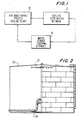
- Fig. 1 represents a typical application for air-conditioning or process cooling in which a cooling plant 10 provides the necessary chilled water to a cooling distribution network 12 with the thermal storage being provided by a large water tank 14.
- the cooling plant 10 may relate to a district air-conditioning system or to a process cooling application and in both cases the thermal storage takes place in the water tank 14.
- Fig. 2 represents a typical water tank 20 used in a system such as that of Fig. 1.
- this tank may be as big as 38.7 metres (127 feet) in diameter and 27.4 metres (90 feet) high. It is in this large volume of cooling liquid that the stratification must be maintained, so that the storage of both warm and chilled water in the same tank can be accomplished.
- such a storage tank 20 typically has a nonmixing inlet and outlet system to prevent agitation and mixing of the cooled water and warm water as it is introduced into and drawn out of the tank.
- a nonmixing inlet and outlet system to prevent agitation and mixing of the cooled water and warm water as it is introduced into and drawn out of the tank.
- Such nonmixing can be accomplished using radial diffuser plates at the inlet/outlet at the top and bottom of the tank, shown respectively at 22 and 24.
- Such nonmixing can also be accomplished using a two-pipe baffle system at each inlet and outlet. In such baffle system two pipes, not shown, are concentrically arranged with the apertures in the pipes being offset relative to each other.
- thermocline is the area of mixed temperature water between the 5.5°C (42°F) chilled water and the 15.55°C (60°F) return water. It will be understood that any mixing, as represented by a very thick thermocline layer, will reduce the amount of chilled water that can be stored at night for delivery to buildings at the required temperature during the day. This interface layer or band will move up and down in the tank as chilled water is taken from or added to the tank.
- Maintaining this stratification is an important feature of the present invention and relates to the separation of liquids at different densities in a container when not exposed to turbulence or mixing due to fluid flow.
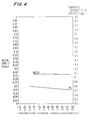
- the present invention teaches to take steps to change the density of the solution in proportion to the temperature change. Referring to Fig. 4, it is seen that the colder the solution, the higher the density. For example, assume that the tank 20 is full of solution at 12.22°C (54°F) with a density of 1.048 x 10 3 kg.m- 3 (8.75 lbs/gal) and chilled solution is introduced through inlet diffuser 24 at -1.11°C (30°F) with a density of 1.052 x 10 3 kg.m -3 (8.781bs/gal).
- the -1.11°C (30°F) solution will form a layer at the bottom of the tank 20 and will remain separated indefinitely from the 12.22°C (54°F) solution, so long as there is no change in solution layer temperature.
- the above-described interface band or thermocline will exist between the two solution layers.
- the addition of sodium nitrite and sodium nitrate alone or in combination will permit stratified storage of the thermal mass below the 4.4°C (40.0°F) limit permitted when utilizing water alone.
- a 7% solution of sodium nitrite and sodium nitrate in a 2 to 1 ratio is provided, however, the solution concentration can range from below 3% to at least 25%.
- 3%, 15% and 25% solutions of sodium nitrite and sodium nitrate in a 2 to 1 ratio are provided.
- the use of the sodium nitrite/sodium nitrate solution permits storage of the chilled solution at lower temperatures than with only water.
- the minimum temperature at which pure water can be stored in a stratification mode is 3.88°C (39°F).
- the density of water decreases, thus water colder than 3.88°C (39°F) will rise in the tank and the desired stratification will not take place.
- the present invention teaches that even when using concentrations for thermal storage of less than 5%, but not less than 3%, microbiological growth does not occur at these concentrations and, in fact, the solution has been found to be microbicidal.
- a further advantage in utilizing sodium nitrite to lower the temperature of the chilled water is that sodium nitrite is readily oxidized to nitrate, either biologically or by chlorination. This means that such nitrate can be removed from the waste water by natural biological action or by aquatic vegetation.
- the present invention teaches to depress the freezing point of the solution to permit cooling below 0°C (32°F) and also to produce a temperature/density gradient to allow the production of a stratified thermal mass.
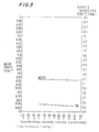
- Fig. 3 represents a straight line temperature/density curve attainable in keeping with the present invention by using a 3% sodium nitrite/sodium nitrate solution in a 2 to 1 ratio.
- Fig. 4 represents a straight line temperature/density curve attainable in keeping with the present invention by using a 7% sodium nitrite/sodium nitrate solution in a 2 to 1 ratio.
- Fig. 3 represents a straight line temperature/density curve attainable in keeping with the present invention by using a 3% sodium nitrite/sodium nitrate solution in a 2 to 1 ratio.
- Fig. 4 represents a straight line temperature/density curve attainable in keeping with the present invention by using a 7% sodium nitrite/sodium nitrate
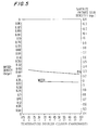
- Fig. 5 represents a straight line temperature/density curve attainable in keeping with the present invention by using a 15% sodium nitrite/sodium nitrate solution in a 2 to 1 ratio.
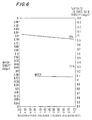
- Fig. 6 represents a straight line temperature/density curve attainable in keeping with the present invention by using a 25% sodium nitrite/nitrate solution in a 2 to 1 ratio.
- a further advantage obtained by using sodium nitrite/sodium nitrate according to the present invention is the provision of corrosion inhibition for the metals employed in the cooling system.
- chloride and sulphate salts might be generally less expensive than sodium nitrite/sodium nitrate, they are corrosive and require the addition of corrosion inhibitors.
- the most effective and only commercially available chloride corrosion inhibitor is chromate, however, because of environmental restrictions chromate can not be used.
- the thermal storage operates at a chilled water temperature of -1.1°C (30°F) and in order to provide freeze protection in the system and equipment, a solution strength of 3% sodium nitrite and sodium nitrate in a 2 to 1 ratio was prepared that has a freezing point of -1.6° (29.2°F). This results in an approximate straight line temperature density curve over the system operating temperature range of -1.1°C (30°F) to 13.3°C (56°F).
- Tests relating to the use of a corrosion coupon and the linear polarization resistance technique showed the 7% solution was not only non-corrosive to mild steel but also creates corrosion inhibitors, and is only moderately corrosive to copper and copper alloys. In this example, a 5.5 ppm of tolyltriazole was added and this sharply decreased the corrosion rate for copper and brass.
- the thermal storage operates at a chilled water temperature of -1.1°C (30°F) and in order to provide freeze protection in the system and equipment, a solution strength of 7% sodium nitrite and sodium nitrate in a 2 to 1 ratio was prepared that has a freezing point of -3.75°C (25.25°F). This results in an approximate straight line temperature density curve over the system operating temperature range of -1.1°C (30°F) to 13.3°C (56°F).
- the thermal storage operates at a chilled water temperature of -1.1°C (30°F) and in order to provide freeze protection in the system and equipment, a solution strength of 15% sodium nitrite and sodium nitrate in a 2 to 1 ratio was prepared that has a freezing point of -7.5°C (18.5°F). This results in an approximate straight line temperature density curve over the system operating temperature range of -1.1°C (30°F) to 13.3°C (56°F).
- the thermal storage operates at a chilled water temperature of -1.1°C (30°F) and in order to provide freeze protection in the system and equipment, a solution strength of 25% sodium nitrite and sodium nitrate in a 2 to 1 ratio was prepared that has a freezing point of -13.2°C (8.3°F). This results in an approximate straight line temperature density curve over the system operating temperature range of -1.1°C (30°F) to 13.3°C (56°F).
- the solutions of the sodium nitrite and sodium nitrate mentioned above were tested for microbial activity using an inoculation procedure on the test solution and a control sample of tap water. The results showed that the nitrite/nitrate solutions of 3% concentration or more are inhibitory or microbicidal to microbiological growth. At concentrations of less than 3%, the nitrite/nitrate solutions are no longer microbicidal.
Landscapes
- Engineering & Computer Science (AREA)
- Chemical & Material Sciences (AREA)
- Thermal Sciences (AREA)
- Physics & Mathematics (AREA)
- Combustion & Propulsion (AREA)
- Materials Engineering (AREA)
- Chemical Kinetics & Catalysis (AREA)
- Organic Chemistry (AREA)
- Mechanical Engineering (AREA)
- General Engineering & Computer Science (AREA)
- Other Air-Conditioning Systems (AREA)
- Filling Or Discharging Of Gas Storage Vessels (AREA)
- Management, Administration, Business Operations System, And Electronic Commerce (AREA)
- Air Conditioning Control Device (AREA)
- Agricultural Chemicals And Associated Chemicals (AREA)
Claims (9)
- Procédé de stockage à basse température d'eau refroidie stratifiée dans une cuve de stockage thermique, comprenant les étapes de préparation :(a) d'une solution de nitrite de sodium et d'eau ; ou(b) d'une solution de nitrate de sodium et d'eau ; ou(c) d'une solution de nitrite de sodium, de nitrate de sodium et d'eau ;par lequel la cuve contient une couche de la solution refroidie à une température inférieure à x située en dessous d'une couche d'une solution préparée à une température supérieure à x, où dans le cas de la solution (a) ou de la solution (b) x est 4,1 °C (39,4°F) et dans le cas de la solution (c) x est 4,4°C (40°F).stockage de la solution préparée dans une cuve de stockage ;refroidissement d'une partie de la solution préparée, stockée, à une température inférieure à 4,1 °C (39,4°F) ; etintroduction de la solution refroidie au fond de la cuve de stockage,
- Procédé selon la revendication 1, dans lequel l'étape d'introduction comporte l'empêchement du mélange entre la solution refroidie introduite et la solution déjà stockée dans la cuve.
- Procédé selon la revendication 1 ou la revendication 2, dans lequel une solution de 3% à 25% de nitrite de sodium et/ou de nitrate de sodium et d'eau est préparée.
- Procédé selon l'une quelconque des revendications 1 à 3, dans lequel l'étape de préparation comporte l'addition de 5,5 ppm de tolyltriazole.
- Procédé selon l'une quelconque des revendications 1 à 4, dans lequel l'étape de préparation comporte l'étape d'addition du nitrite de sodium et/ou du nitrate de sodium à l'eau dans un rapport de 2 à 1.
- Procédé selon l'une quelconque des revendications 1 à 5, dans lequel une solution de 3% de nitrite de sodium et/ou de nitrate de sodium et d'eau est préparée.
- Procédé selon l'une quelconque des revendications 1 à 5, dans lequel une solution de 7% de nitrite de sodium et/ou de nitrate de sodium et d'eau est préparée.
- Procédé selon l'une quelconque des revendications 1 à 5, dans lequel une solution de 15% de nitrite de sodium et/ou de nitrate de sodium et d'eau est préparée.
- Procédé selon l'une quelconque des revendications 1 à 5, dans lequel une solution de 25% de nitrite de sodium et/ou de nitrate de sodium et d'eau est préparée.
Applications Claiming Priority (2)
| Application Number | Priority Date | Filing Date | Title |
|---|---|---|---|
| US08/538,080 US5655377A (en) | 1994-06-16 | 1995-10-02 | Method of low-temperature stratified chilled water storage |
| US538080 | 1995-10-02 |
Publications (2)
| Publication Number | Publication Date |
|---|---|
| EP0767233A1 EP0767233A1 (fr) | 1997-04-09 |
| EP0767233B1 true EP0767233B1 (fr) | 2000-07-19 |
Family
ID=24145399
Family Applications (1)
| Application Number | Title | Priority Date | Filing Date |
|---|---|---|---|
| EP95650040A Expired - Lifetime EP0767233B1 (fr) | 1995-10-02 | 1995-11-13 | Procédé de stockage à basse température d'eau refroidie stratifiée |
Country Status (12)
| Country | Link |
|---|---|
| US (1) | US5655377A (fr) |
| EP (1) | EP0767233B1 (fr) |
| AR (1) | AR000124A1 (fr) |
| BR (1) | BR9505165A (fr) |
| CA (1) | CA2162769C (fr) |
| CR (1) | CR5212A (fr) |
| DE (1) | DE69518079T2 (fr) |
| ES (1) | ES2152373T3 (fr) |
| MA (1) | MA23981A1 (fr) |
| MX (1) | MX9504743A (fr) |
| MY (1) | MY113736A (fr) |
| WO (1) | WO1997013105A1 (fr) |
Families Citing this family (9)
| Publication number | Priority date | Publication date | Assignee | Title |
|---|---|---|---|---|
| US6848267B2 (en) * | 2002-07-26 | 2005-02-01 | Tas, Ltd. | Packaged chilling systems for building air conditioning and process cooling |
| US6408609B1 (en) * | 2000-06-09 | 2002-06-25 | Chicago Bridge & Iron Company | Method and apparatus for enhancing power output and efficiency of combustion turbines |
| US7856843B2 (en) * | 2006-04-05 | 2010-12-28 | Enis Ben M | Thermal energy storage system using compressed air energy and/or chilled water from desalination processes |
| CN101454060A (zh) * | 2006-04-05 | 2009-06-10 | 本·M·埃尼斯 | 采用压缩空气能量系统的脱盐方法和系统 |
| US8863547B2 (en) * | 2006-04-05 | 2014-10-21 | Ben M. Enis | Desalination method and system using compressed air energy systems |
| US8523643B1 (en) | 2007-06-14 | 2013-09-03 | Switch Communications Group LLC | Electronic equipment data center or co-location facility designs and methods of making and using the same |
| AU2012249235B1 (en) * | 2012-11-14 | 2013-06-20 | Mesh Corporation Pty Ltd | District Cooling System and Thermal Energy Storage Tank System Layout |
| US10247458B2 (en) | 2013-08-21 | 2019-04-02 | Carrier Corporation | Chilled water system efficiency improvement |
| US9803126B1 (en) | 2016-08-23 | 2017-10-31 | H-O-H Water Technology, Inc. | Method of low-temperature liquid containment and transport |
Family Cites Families (11)
| Publication number | Priority date | Publication date | Assignee | Title |
|---|---|---|---|---|
| NL7708304A (nl) * | 1976-07-30 | 1978-02-01 | Crede Helfried | Werkwijze voor het winnen van energie en daar- toe geschikte inrichting. |
| US4109702A (en) * | 1976-08-06 | 1978-08-29 | Greene Norman Donald | Energy storage and retrieval as heat |
| CH628417A5 (de) * | 1978-01-06 | 1982-02-26 | Laszlo Simon | Anlage zum speichern von kontinuierlich erzeugter kaelte und zum stossweisen abgeben mindestens eines teils der gespeicherten kaelte. |
| IL54597A (en) * | 1978-04-30 | 1981-02-27 | Wirguin J | Heat storage in a thermal pond |
| US4446910A (en) * | 1980-05-22 | 1984-05-08 | General Electric Company | Two-phase thermal storage means and method |
| US4595516A (en) * | 1983-12-05 | 1986-06-17 | Matsushita Electric Industrial Co., Ltd. | Heat storage material |
| JPS60126530A (ja) * | 1983-12-08 | 1985-07-06 | Hitachi Zosen C B I Kk | 冷却方法及び装置 |
| US4821794A (en) * | 1988-04-04 | 1989-04-18 | Thermal Energy Storage, Inc. | Clathrate thermal storage system |
| US5065598A (en) * | 1989-09-05 | 1991-11-19 | Mitsubishi Denki Kabushiki Kaisha | Ice thermal storage apparatus |
| US5348080A (en) * | 1990-12-19 | 1994-09-20 | Tokyo Electric Power Company | Latent heat storage apparatus and latent heat storage solution therefor |
| US5465585A (en) * | 1994-06-16 | 1995-11-14 | Trigen Energy Corporation | Method of low-temperature stratified chilled water storage |
-
1995
- 1995-10-02 US US08/538,080 patent/US5655377A/en not_active Expired - Lifetime
- 1995-11-13 ES ES95650040T patent/ES2152373T3/es not_active Expired - Lifetime
- 1995-11-13 MX MX9504743A patent/MX9504743A/es not_active IP Right Cessation
- 1995-11-13 MY MYPI95003436A patent/MY113736A/en unknown
- 1995-11-13 DE DE69518079T patent/DE69518079T2/de not_active Expired - Fee Related
- 1995-11-13 EP EP95650040A patent/EP0767233B1/fr not_active Expired - Lifetime
- 1995-11-13 WO PCT/US1995/014656 patent/WO1997013105A1/fr not_active Ceased
- 1995-11-13 AR AR33421795A patent/AR000124A1/es unknown
- 1995-11-13 BR BR9505165A patent/BR9505165A/pt not_active IP Right Cessation
- 1995-11-14 CA CA002162769A patent/CA2162769C/fr not_active Expired - Fee Related
- 1995-11-21 CR CR5212A patent/CR5212A/es unknown
-
1996
- 1996-10-01 MA MA24361A patent/MA23981A1/fr unknown
Also Published As
| Publication number | Publication date |
|---|---|
| DE69518079D1 (de) | 2000-08-24 |
| CR5212A (es) | 1996-07-02 |
| WO1997013105A1 (fr) | 1997-04-10 |
| CA2162769A1 (fr) | 1997-04-03 |
| MA23981A1 (fr) | 1997-07-01 |
| CA2162769C (fr) | 1999-07-27 |
| MX9504743A (es) | 1997-04-30 |
| AR000124A1 (es) | 1997-05-21 |
| HK1014021A1 (en) | 1999-09-17 |
| US5655377A (en) | 1997-08-12 |
| MY113736A (en) | 2002-05-31 |
| EP0767233A1 (fr) | 1997-04-09 |
| BR9505165A (pt) | 1997-10-21 |
| ES2152373T3 (es) | 2001-02-01 |
| DE69518079T2 (de) | 2001-03-29 |
Similar Documents
| Publication | Publication Date | Title |
|---|---|---|
| US5465585A (en) | Method of low-temperature stratified chilled water storage | |
| US5065598A (en) | Ice thermal storage apparatus | |
| US5655377A (en) | Method of low-temperature stratified chilled water storage | |
| EP1235046B1 (fr) | Materiau de stockage thermique utilisant un dispositif de stockage hydrate et thermique et procede de production de ce materiau | |
| CA2318258C (fr) | Fluide de chauffage et de refroidissement resistant au gel | |
| JPS61500036A (ja) | 加圧式氷貯蔵冷水装置 | |
| Gao et al. | Experimental study on the fouling and heat transfer characteristics of enhanced tubes used in a cooling tower water system with the actual water quality | |
| Butler et al. | Some important aspects of corrosion in central heating systems | |
| HK1014021B (en) | Method of low-temperature stratified chilled water storage | |
| JP2004331935A (ja) | 冷熱輸送媒体 | |
| JP2006176674A (ja) | 冷熱輸送媒体 | |
| SK118397A3 (en) | Glycol-free frost resistant cooling liquids | |
| Fang et al. | Analysis of the optimization on application of seawater slurry ice in coastal areas | |
| CN105841388B (zh) | 一种综合利用废热的盐溶液制冷机 | |
| Wild | Chilling Maple Sap | |
| EP1543284A1 (fr) | Systeme de refroidissement et methode d'utilisation | |
| JPH0792307B2 (ja) | 氷蓄熱装置 | |
| Eng et al. | Handbook on indirect refrigeration and heat pump systems | |
| SU1620792A1 (ru) | Аккумул тор холода | |
| Hettler Jr | A filter and chiller for an open seawater system | |
| Memet et al. | Romanian Reefer Trade Face to Face with Efficiency and Environment | |
| Slesarenko et al. | The account of heat exchange features when modelling scale formation at distillation plants | |
| AU611669B2 (en) | Ice building, chilled water system and method | |
| Chiu | A study of the ice making operation in the desalination freezing process based on the inversion of melting points due to applied pressure | |
| JPS5925034B2 (ja) | 銅用防食剤 |
Legal Events
| Date | Code | Title | Description |
|---|---|---|---|
| PUAI | Public reference made under article 153(3) epc to a published international application that has entered the european phase |
Free format text: ORIGINAL CODE: 0009012 |
|
| AK | Designated contracting states |
Kind code of ref document: A1 Designated state(s): BE DE ES FR GB IT |
|
| 17P | Request for examination filed |
Effective date: 19970319 |
|
| GRAG | Despatch of communication of intention to grant |
Free format text: ORIGINAL CODE: EPIDOS AGRA |
|
| 17Q | First examination report despatched |
Effective date: 19991012 |
|
| GRAG | Despatch of communication of intention to grant |
Free format text: ORIGINAL CODE: EPIDOS AGRA |
|
| GRAH | Despatch of communication of intention to grant a patent |
Free format text: ORIGINAL CODE: EPIDOS IGRA |
|
| GRAH | Despatch of communication of intention to grant a patent |
Free format text: ORIGINAL CODE: EPIDOS IGRA |
|
| GRAA | (expected) grant |
Free format text: ORIGINAL CODE: 0009210 |
|
| AK | Designated contracting states |
Kind code of ref document: B1 Designated state(s): BE DE ES FR GB IT |
|
| REF | Corresponds to: |
Ref document number: 69518079 Country of ref document: DE Date of ref document: 20000824 |
|
| ITF | It: translation for a ep patent filed | ||
| ET | Fr: translation filed | ||
| REG | Reference to a national code |
Ref country code: ES Ref legal event code: FG2A Ref document number: 2152373 Country of ref document: ES Kind code of ref document: T3 |
|
| PLBE | No opposition filed within time limit |
Free format text: ORIGINAL CODE: 0009261 |
|
| STAA | Information on the status of an ep patent application or granted ep patent |
Free format text: STATUS: NO OPPOSITION FILED WITHIN TIME LIMIT |
|
| 26N | No opposition filed | ||
| REG | Reference to a national code |
Ref country code: GB Ref legal event code: IF02 |
|
| PGFP | Annual fee paid to national office [announced via postgrant information from national office to epo] |
Ref country code: DE Payment date: 20041111 Year of fee payment: 10 |
|
| PG25 | Lapsed in a contracting state [announced via postgrant information from national office to epo] |
Ref country code: IT Free format text: LAPSE BECAUSE OF NON-PAYMENT OF DUE FEES;WARNING: LAPSES OF ITALIAN PATENTS WITH EFFECTIVE DATE BEFORE 2007 MAY HAVE OCCURRED AT ANY TIME BEFORE 2007. THE CORRECT EFFECTIVE DATE MAY BE DIFFERENT FROM THE ONE RECORDED. Effective date: 20051113 |
|
| PG25 | Lapsed in a contracting state [announced via postgrant information from national office to epo] |
Ref country code: DE Free format text: LAPSE BECAUSE OF NON-PAYMENT OF DUE FEES Effective date: 20060601 |
|
| PGFP | Annual fee paid to national office [announced via postgrant information from national office to epo] |
Ref country code: GB Payment date: 20061108 Year of fee payment: 12 Ref country code: FR Payment date: 20061108 Year of fee payment: 12 |
|
| PGFP | Annual fee paid to national office [announced via postgrant information from national office to epo] |
Ref country code: ES Payment date: 20061222 Year of fee payment: 12 |
|
| PGFP | Annual fee paid to national office [announced via postgrant information from national office to epo] |
Ref country code: BE Payment date: 20070126 Year of fee payment: 12 |
|
| BERE | Be: lapsed |
Owner name: *TRIGEN ENERGY CORP. Effective date: 20071130 |
|
| GBPC | Gb: european patent ceased through non-payment of renewal fee |
Effective date: 20071113 |
|
| PG25 | Lapsed in a contracting state [announced via postgrant information from national office to epo] |
Ref country code: BE Free format text: LAPSE BECAUSE OF NON-PAYMENT OF DUE FEES Effective date: 20071130 |
|
| REG | Reference to a national code |
Ref country code: FR Ref legal event code: ST Effective date: 20080930 |
|
| PG25 | Lapsed in a contracting state [announced via postgrant information from national office to epo] |
Ref country code: GB Free format text: LAPSE BECAUSE OF NON-PAYMENT OF DUE FEES Effective date: 20071113 |
|
| REG | Reference to a national code |
Ref country code: ES Ref legal event code: FD2A Effective date: 20071114 |
|
| PG25 | Lapsed in a contracting state [announced via postgrant information from national office to epo] |
Ref country code: FR Free format text: LAPSE BECAUSE OF NON-PAYMENT OF DUE FEES Effective date: 20071130 Ref country code: ES Free format text: LAPSE BECAUSE OF NON-PAYMENT OF DUE FEES Effective date: 20071114 |