EP0767329A1 - Dispositif d'étanchéité pour une chambre annulaire - Google Patents
Dispositif d'étanchéité pour une chambre annulaire Download PDFInfo
- Publication number
- EP0767329A1 EP0767329A1 EP96114761A EP96114761A EP0767329A1 EP 0767329 A1 EP0767329 A1 EP 0767329A1 EP 96114761 A EP96114761 A EP 96114761A EP 96114761 A EP96114761 A EP 96114761A EP 0767329 A1 EP0767329 A1 EP 0767329A1
- Authority
- EP
- European Patent Office
- Prior art keywords
- segments
- peripheral edges
- individual segments
- another
- sealing element
- Prior art date
- Legal status (The legal status is an assumption and is not a legal conclusion. Google has not performed a legal analysis and makes no representation as to the accuracy of the status listed.)
- Granted
Links
- 238000007789 sealing Methods 0.000 title claims abstract description 33
- 230000002093 peripheral effect Effects 0.000 claims abstract description 26
- 239000012530 fluid Substances 0.000 claims description 4
- 238000010276 construction Methods 0.000 claims description 2
- 239000007769 metal material Substances 0.000 claims description 2
- 238000007664 blowing Methods 0.000 description 2
- 238000004519 manufacturing process Methods 0.000 description 2
- 230000015572 biosynthetic process Effects 0.000 description 1
- 238000001816 cooling Methods 0.000 description 1
- 238000003780 insertion Methods 0.000 description 1
- 230000037431 insertion Effects 0.000 description 1
- 229910000679 solder Inorganic materials 0.000 description 1
- 238000005476 soldering Methods 0.000 description 1
- 239000007787 solid Substances 0.000 description 1
- 238000003466 welding Methods 0.000 description 1
Images
Classifications
-
- F—MECHANICAL ENGINEERING; LIGHTING; HEATING; WEAPONS; BLASTING
- F16—ENGINEERING ELEMENTS AND UNITS; GENERAL MEASURES FOR PRODUCING AND MAINTAINING EFFECTIVE FUNCTIONING OF MACHINES OR INSTALLATIONS; THERMAL INSULATION IN GENERAL
- F16J—PISTONS; CYLINDERS; SEALINGS
- F16J15/00—Sealings
- F16J15/02—Sealings between relatively-stationary surfaces
- F16J15/06—Sealings between relatively-stationary surfaces with solid packing compressed between sealing surfaces
- F16J15/08—Sealings between relatively-stationary surfaces with solid packing compressed between sealing surfaces with exclusively metal packing
- F16J15/0887—Sealings between relatively-stationary surfaces with solid packing compressed between sealing surfaces with exclusively metal packing the sealing effect being obtained by elastic deformation of the packing
-
- F—MECHANICAL ENGINEERING; LIGHTING; HEATING; WEAPONS; BLASTING
- F01—MACHINES OR ENGINES IN GENERAL; ENGINE PLANTS IN GENERAL; STEAM ENGINES
- F01D—NON-POSITIVE DISPLACEMENT MACHINES OR ENGINES, e.g. STEAM TURBINES
- F01D11/00—Preventing or minimising internal leakage of working-fluid, e.g. between stages
- F01D11/005—Sealing means between non relatively rotating elements
Definitions
- the invention relates to a device for sealing an annular space lying between two components that can be moved relative to one another against exposure to fluid, in particular hot gas, with an annular disk-shaped sealing element which engages in two radially opposite circumferential grooves of the two components.
- the disk-shaped sealing element is designed as a solid part, the sealing element having a spherical surface contour in the region of the circumferential groove in order to achieve a line seal between the sealing element and the end walls of the circumferential groove.
- a disadvantage of a sealing device designed in this way is that the play between the spherical surface of the sealing element and the end walls of the circumferential groove can change very quickly, in particular as a result of a change in temperature of the device, and thus an optimal play which ensures the highest seal cannot be maintained in practical operation . This is especially true when annular spaces on thermal machines, such as. As turbomachinery, are to be sealed against hot gas because there are high temperature gradients. The disadvantageous consequence of too much sealing play is blowing through with a corresponding loss of cooling air or, if the fluid to be sealed is hot gas, burning of the sealing device.
- the object is achieved in that, in a generic device for sealing described above, the annular disk-shaped sealing element is formed from flat segments and the peripheral edge regions of the segments have at least on one of their two peripheral edges flanged peripheral edges in both axial directions, each with their own prestress against end faces of the Apply circumferential groove.
- the device according to the invention has the advantage over previously known sealing devices that, due to the inherent elasticity with which the peripheral edges bear against the end faces of the peripheral groove, a constant play can be maintained over wide operating ranges and thus the task of high fluid tightness on the one hand and relative mobility on the other hand can be achieved.
- the flanged peripheral edges can have been created by massive forming of a full ring disc, the edges of which are first formed and which are then divided into segments.
- each segment is constructed from two individual segments which are set in mirror image against one another and each flanged in an axial direction. The manufacturing effort can be reduced.
- the individual segments should be fastened to one another. In this way, a concentric positioning of the two individual segments is guaranteed and thus the same spring behavior of the peripheral edges against the end faces of the peripheral groove.
- the individual segments are arranged so that the butt joints of the opposing individual segments are offset in the circumferential direction.
- the individual segments from which each segment is formed are preferably structurally identical.
- the segments are preferably made of metallic material, which ensures that an inherent prestress is maintained over a high temperature range.
- the spring properties of the flanged peripheral edges can be changed by providing an intermediate layer between the individual segments.
- the spring characteristic of the peripheral edges is set by the choice of the flanging radius. With a smaller flare radius, this results in a harder spring characteristic than with a large flare radius.
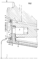
- FIG. 1 The longitudinal section shown in FIG. 1 is a section of a turbomachine, the main axis of rotation of which is designated by 1.
- a seal carrier 10 which is rotationally symmetrical with respect to the axis of rotation 1 is in a rotationally symmetrical housing-side Component 20 held over spring bolts 3.
- the components 10 and 20 form an annular space 30 which is to be sealed off from a hot gas space H, radial and axial limited mobility between the components 10 and 20 being permissible.
- a disk-shaped sealing element formed from segments 41 is provided, which engages radially on the inside in a circumferential groove 11 of the component 10, radially on the outside in a circumferential groove 21 of the component 20.
- the minimum number of segments 41 for a sealing element is 2, which is then two Half-circle segments; however, several segments 41 formed by regularly dividing a ring can also be provided.
- Each segment 41 consists of two individual segments 41a and 41b, which are set against one another in mirror image and each have circumferential edges 43, 45 flanged in an axial direction.
- both the inner peripheral edge 44 and the outer peripheral edge 42 are each provided with flanged peripheral edges 45 and 43, respectively.
- a segment 41 is permanently installed on the inner or outer circumference and is only provided on the other circumferential edge with the flanged circumferential edges.
- the flanged circumferential edges 43, 45 bear under their own prestress against end faces 22, 23 of the outer circumferential groove 21 or against end faces 12, 13 of the inner circumferential groove 11. In this way, two successive annular sealing lines between the sealing element and the components 10 and 20 are created between the hot gas space H and the annular space 30 to be sealed. Due to the elastic design of the sealing element and the inherent pretension of the flared peripheral edges, the set play on the sealing lines can be maintained both in the axial and in the radial direction even with limited relative movement of the components 10, 20 against one another.
- the individual segments 41a, 41b are constructed identically and are attached to one another by means of soldering (solder points 47). Alternatively, welding or other joining could be carried out or the individual segments 41a, 41b could not be fastened.
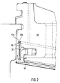
- the same components are designated with the same reference numerals as in FIG. 1.
- the construction of the sealing element in that an intermediate layer 46 is inserted between the individual segments 41a, 41b.
- the insertion of the intermediate layer can offer manufacturing advantages as well as bring about a variation in the spring stiffness of the respective flanged edges.
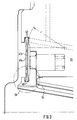
- the embodiment according to FIG. 3 is largely the same as the embodiment according to FIG. 1. Only the flanging radius r of the individual segments 41a, 41b is chosen larger in the embodiment according to FIG. 3 than in the embodiment according to FIG. 1. Otherwise the individual segments or The sealing element results in a softer spring characteristic of the flared peripheral edges 43, 45 due to the larger flanging radius.
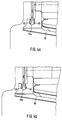
- FIG. 4a shows an alternative cross-sectional shape of the circumferential groove, which is designated 11a here.
- the undercut ensures that the individual segments are secured.
- the conical formation of the groove cheeks in the circumferential groove 11b according to FIG. 4b facilitates the assembly of the individual segments.
Landscapes
- Engineering & Computer Science (AREA)
- General Engineering & Computer Science (AREA)
- Mechanical Engineering (AREA)
- Gasket Seals (AREA)
Applications Claiming Priority (2)
| Application Number | Priority Date | Filing Date | Title |
|---|---|---|---|
| DE1995137282 DE19537282C2 (de) | 1995-10-06 | 1995-10-06 | Vorrichtung zur Abdichtung eines Ringraumes gegen Beaufschlagung durch Fluid |
| DE19537282 | 1995-10-06 |
Publications (2)
| Publication Number | Publication Date |
|---|---|
| EP0767329A1 true EP0767329A1 (fr) | 1997-04-09 |
| EP0767329B1 EP0767329B1 (fr) | 2002-04-03 |
Family
ID=7774211
Family Applications (1)
| Application Number | Title | Priority Date | Filing Date |
|---|---|---|---|
| EP19960114761 Expired - Lifetime EP0767329B1 (fr) | 1995-10-06 | 1996-09-14 | Dispositif d'étanchéité pour une chambre annulaire |
Country Status (2)
| Country | Link |
|---|---|
| EP (1) | EP0767329B1 (fr) |
| DE (1) | DE19537282C2 (fr) |
Cited By (4)
| Publication number | Priority date | Publication date | Assignee | Title |
|---|---|---|---|---|
| EP1832716A2 (fr) | 2006-03-09 | 2007-09-12 | United Technologies Corporation | Dispositif d'étanchéité d'un composant segmenté |
| WO2008033897A1 (fr) * | 2006-09-12 | 2008-03-20 | Parker-Hannifin Corporation | Ensemble joint |
| US8016549B2 (en) | 2006-07-13 | 2011-09-13 | United Technologies Corporation | Turbine engine alloys and crystalline orientations |
| KR20140139409A (ko) * | 2013-05-27 | 2014-12-05 | 가부시끼가이샤 도시바 | 정지부 시일 구조 |
Families Citing this family (1)
| Publication number | Priority date | Publication date | Assignee | Title |
|---|---|---|---|---|
| DE10209295B4 (de) * | 2002-03-01 | 2010-12-09 | Alstom Technology Ltd. | Spaltdichtung bei einer Gasturbine |
Citations (4)
| Publication number | Priority date | Publication date | Assignee | Title |
|---|---|---|---|---|
| DE1253950B (de) * | 1963-02-16 | 1967-11-09 | Maschf Augsburg Nuernberg Ag | Dichtring fuer die Abdichtung von Zylinderdeckeln fuer Brennkraftmaschinen |
| US3754766A (en) * | 1971-11-11 | 1973-08-28 | United Aircraft Corp | Spring type ring seal |
| FR2246782A1 (en) * | 1973-10-01 | 1975-05-02 | Gen Electric | Sealing ring with initial preloading - has axially projecting lip at inner or outer edge of radial surfaces |
| GB2093537A (en) * | 1981-02-19 | 1982-09-02 | Westinghouse Electric Corp | Seals |
Family Cites Families (3)
| Publication number | Priority date | Publication date | Assignee | Title |
|---|---|---|---|---|
| DE926665C (de) * | 1952-01-16 | 1955-04-21 | Siemens Ag | Elastischer Zwischenring geringer Wandstaerke zur dampfdichten, waermebeweglichen Abstuetzung eines Turbinenteiles |
| GB1148388A (en) * | 1965-07-15 | 1969-04-10 | British Aircraft Corp Ltd | Static fluid tight seals |
| FR2031924A5 (fr) * | 1969-02-13 | 1970-11-20 | Commissariat Energie Atomique |
-
1995
- 1995-10-06 DE DE1995137282 patent/DE19537282C2/de not_active Expired - Fee Related
-
1996
- 1996-09-14 EP EP19960114761 patent/EP0767329B1/fr not_active Expired - Lifetime
Patent Citations (4)
| Publication number | Priority date | Publication date | Assignee | Title |
|---|---|---|---|---|
| DE1253950B (de) * | 1963-02-16 | 1967-11-09 | Maschf Augsburg Nuernberg Ag | Dichtring fuer die Abdichtung von Zylinderdeckeln fuer Brennkraftmaschinen |
| US3754766A (en) * | 1971-11-11 | 1973-08-28 | United Aircraft Corp | Spring type ring seal |
| FR2246782A1 (en) * | 1973-10-01 | 1975-05-02 | Gen Electric | Sealing ring with initial preloading - has axially projecting lip at inner or outer edge of radial surfaces |
| GB2093537A (en) * | 1981-02-19 | 1982-09-02 | Westinghouse Electric Corp | Seals |
Cited By (9)
| Publication number | Priority date | Publication date | Assignee | Title |
|---|---|---|---|---|
| EP1832716A2 (fr) | 2006-03-09 | 2007-09-12 | United Technologies Corporation | Dispositif d'étanchéité d'un composant segmenté |
| EP1832716A3 (fr) * | 2006-03-09 | 2008-05-21 | United Technologies Corporation | Dispositif d'étanchéité d'un composant segmenté |
| US8016549B2 (en) | 2006-07-13 | 2011-09-13 | United Technologies Corporation | Turbine engine alloys and crystalline orientations |
| WO2008033897A1 (fr) * | 2006-09-12 | 2008-03-20 | Parker-Hannifin Corporation | Ensemble joint |
| US7901186B2 (en) | 2006-09-12 | 2011-03-08 | Parker Hannifin Corporation | Seal assembly |
| KR20140139409A (ko) * | 2013-05-27 | 2014-12-05 | 가부시끼가이샤 도시바 | 정지부 시일 구조 |
| JP2014227987A (ja) * | 2013-05-27 | 2014-12-08 | 株式会社東芝 | 静止部シール構造 |
| EP2813670A3 (fr) * | 2013-05-27 | 2015-04-29 | Kabushiki Kaisha Toshiba | Structure d'étanchéité entre parties fixes |
| US9464535B2 (en) | 2013-05-27 | 2016-10-11 | Kabushiki Kaisha Toshiba | Stationary part sealing structure |
Also Published As
| Publication number | Publication date |
|---|---|
| EP0767329B1 (fr) | 2002-04-03 |
| DE19537282A1 (de) | 1997-04-17 |
| DE19537282C2 (de) | 1999-02-18 |
Similar Documents
| Publication | Publication Date | Title |
|---|---|---|
| DE69820960T2 (de) | Kombinierte Bürsten/Labyrinth Dichtung für Rotationsmaschinen | |
| DE3836474C2 (de) | Bürstendichtung | |
| DE3878589T2 (de) | Buerstendichtungen. | |
| DE69527582T2 (de) | Beschaufelter diffusor | |
| DE69812052T2 (de) | Turbinenmantelring | |
| DE4017861C2 (fr) | ||
| DE69218599T2 (de) | Dichtung für rotierende Teile | |
| DE10197208T5 (de) | Dichtungsanordnung und Umlaufmaschine, die eine solche Dichtung enthält | |
| DE29812929U1 (de) | Flachringdichtung | |
| EP1738096B1 (fr) | Procede de fabrication de garnitures d'etancheite a lamelles | |
| DE4006498C2 (de) | Vorrichtung zum Abdichten eines Raumes in einer Turbomaschine | |
| DE60018396T2 (de) | Selbstzentrierende bürstendichtung | |
| DE69812165T2 (de) | Trägerelement für einen turbinenleitapparat | |
| DE2847252C3 (de) | Anordnung zur Abdichtung der Stoßstelle zwischen zwei Statorteilen einer. Turbomaschine | |
| DE3830762C2 (de) | Einrichtung zur Halterung eines Mantelringes in Gasturbinen | |
| DE60018864T2 (de) | Dichtringe für eine verlustarme flexible Kupplung von Gasleitungen | |
| EP0893576B1 (fr) | Connexion d' éléments rotatifs | |
| DE19537282C2 (de) | Vorrichtung zur Abdichtung eines Ringraumes gegen Beaufschlagung durch Fluid | |
| DE3226866C2 (de) | Vorrichtung zum Abdichten eines Drehrohres | |
| EP1573238B1 (fr) | Ensemble joint | |
| EP3485185B1 (fr) | Joint etanche aux gaz | |
| AT522694B1 (de) | Wellendichtung zum Abdichten von Rotoren | |
| DE19735932C1 (de) | Wellenabdichtung einer Turbomaschine | |
| DE4201246C2 (de) | Dichtungsanordnung für eine im Querschnitt kreisförmige Kolbenstange, insbesondere an Kolbenkompressoren | |
| DE2351767B2 (de) | Wellendichtung zur Abdichtung zweier Medien |
Legal Events
| Date | Code | Title | Description |
|---|---|---|---|
| PUAI | Public reference made under article 153(3) epc to a published international application that has entered the european phase |
Free format text: ORIGINAL CODE: 0009012 |
|
| AK | Designated contracting states |
Kind code of ref document: A1 Designated state(s): CH FR GB IT LI SE |
|
| 17P | Request for examination filed |
Effective date: 19970304 |
|
| 17Q | First examination report despatched |
Effective date: 19990713 |
|
| RAP1 | Party data changed (applicant data changed or rights of an application transferred) |
Owner name: MTU AERO ENGINES GMBH |
|
| GRAG | Despatch of communication of intention to grant |
Free format text: ORIGINAL CODE: EPIDOS AGRA |
|
| GRAG | Despatch of communication of intention to grant |
Free format text: ORIGINAL CODE: EPIDOS AGRA |
|
| GRAH | Despatch of communication of intention to grant a patent |
Free format text: ORIGINAL CODE: EPIDOS IGRA |
|
| GRAH | Despatch of communication of intention to grant a patent |
Free format text: ORIGINAL CODE: EPIDOS IGRA |
|
| REG | Reference to a national code |
Ref country code: GB Ref legal event code: IF02 |
|
| GRAA | (expected) grant |
Free format text: ORIGINAL CODE: 0009210 |
|
| AK | Designated contracting states |
Kind code of ref document: B1 Designated state(s): CH FR GB IT LI SE |
|
| REG | Reference to a national code |
Ref country code: CH Ref legal event code: NV Representative=s name: ISLER & PEDRAZZINI AG Ref country code: CH Ref legal event code: EP |
|
| GBT | Gb: translation of ep patent filed (gb section 77(6)(a)/1977) |
Effective date: 20020614 |
|
| ET | Fr: translation filed | ||
| PLBE | No opposition filed within time limit |
Free format text: ORIGINAL CODE: 0009261 |
|
| STAA | Information on the status of an ep patent application or granted ep patent |
Free format text: STATUS: NO OPPOSITION FILED WITHIN TIME LIMIT |
|
| 26N | No opposition filed |
Effective date: 20030106 |
|
| REG | Reference to a national code |
Ref country code: CH Ref legal event code: PCAR Free format text: ISLER & PEDRAZZINI AG;POSTFACH 1772;8027 ZUERICH (CH) |
|
| PGFP | Annual fee paid to national office [announced via postgrant information from national office to epo] |
Ref country code: CH Payment date: 20110923 Year of fee payment: 16 |
|
| PGFP | Annual fee paid to national office [announced via postgrant information from national office to epo] |
Ref country code: GB Payment date: 20120920 Year of fee payment: 17 Ref country code: SE Payment date: 20120919 Year of fee payment: 17 |
|
| PGFP | Annual fee paid to national office [announced via postgrant information from national office to epo] |
Ref country code: FR Payment date: 20121010 Year of fee payment: 17 |
|
| PGFP | Annual fee paid to national office [announced via postgrant information from national office to epo] |
Ref country code: IT Payment date: 20120926 Year of fee payment: 17 |
|
| REG | Reference to a national code |
Ref country code: SE Ref legal event code: EUG |
|
| PG25 | Lapsed in a contracting state [announced via postgrant information from national office to epo] |
Ref country code: SE Free format text: LAPSE BECAUSE OF NON-PAYMENT OF DUE FEES Effective date: 20130915 |
|
| REG | Reference to a national code |
Ref country code: CH Ref legal event code: PL |
|
| GBPC | Gb: european patent ceased through non-payment of renewal fee |
Effective date: 20130914 |
|
| REG | Reference to a national code |
Ref country code: FR Ref legal event code: ST Effective date: 20140530 |
|
| PG25 | Lapsed in a contracting state [announced via postgrant information from national office to epo] |
Ref country code: LI Free format text: LAPSE BECAUSE OF NON-PAYMENT OF DUE FEES Effective date: 20130930 Ref country code: GB Free format text: LAPSE BECAUSE OF NON-PAYMENT OF DUE FEES Effective date: 20130914 Ref country code: CH Free format text: LAPSE BECAUSE OF NON-PAYMENT OF DUE FEES Effective date: 20130930 |
|
| PG25 | Lapsed in a contracting state [announced via postgrant information from national office to epo] |
Ref country code: FR Free format text: LAPSE BECAUSE OF NON-PAYMENT OF DUE FEES Effective date: 20130930 Ref country code: IT Free format text: LAPSE BECAUSE OF NON-PAYMENT OF DUE FEES Effective date: 20130914 |