EP0767340A2 - Entladungslampe mit einer lichtdurchlässigen, leitfähigen Beschichtung zur RF-Begrenzung und Aufwärmung, und diese enthaltende Lampenanordnung - Google Patents
Entladungslampe mit einer lichtdurchlässigen, leitfähigen Beschichtung zur RF-Begrenzung und Aufwärmung, und diese enthaltende Lampenanordnung Download PDFInfo
- Publication number
- EP0767340A2 EP0767340A2 EP96115511A EP96115511A EP0767340A2 EP 0767340 A2 EP0767340 A2 EP 0767340A2 EP 96115511 A EP96115511 A EP 96115511A EP 96115511 A EP96115511 A EP 96115511A EP 0767340 A2 EP0767340 A2 EP 0767340A2
- Authority
- EP
- European Patent Office
- Prior art keywords
- lamp
- light
- conductive coating
- discharge lamp
- discharge
- Prior art date
- Legal status (The legal status is an assumption and is not a legal conclusion. Google has not performed a legal analysis and makes no representation as to the accuracy of the status listed.)
- Granted
Links
Images



Classifications
-
- F—MECHANICAL ENGINEERING; LIGHTING; HEATING; WEAPONS; BLASTING
- F21—LIGHTING
- F21V—FUNCTIONAL FEATURES OR DETAILS OF LIGHTING DEVICES OR SYSTEMS THEREOF; STRUCTURAL COMBINATIONS OF LIGHTING DEVICES WITH OTHER ARTICLES, NOT OTHERWISE PROVIDED FOR
- F21V25/00—Safety devices structurally associated with lighting devices
-
- H—ELECTRICITY
- H01—ELECTRIC ELEMENTS
- H01J—ELECTRIC DISCHARGE TUBES OR DISCHARGE LAMPS
- H01J61/00—Gas-discharge or vapour-discharge lamps
- H01J61/02—Details
- H01J61/30—Vessels; Containers
- H01J61/32—Special longitudinal shape, e.g. for advertising purposes
-
- F—MECHANICAL ENGINEERING; LIGHTING; HEATING; WEAPONS; BLASTING
- F21—LIGHTING
- F21S—NON-PORTABLE LIGHTING DEVICES; SYSTEMS THEREOF; VEHICLE LIGHTING DEVICES SPECIALLY ADAPTED FOR VEHICLE EXTERIORS
- F21S41/00—Illuminating devices specially adapted for vehicle exteriors, e.g. headlamps
- F21S41/10—Illuminating devices specially adapted for vehicle exteriors, e.g. headlamps characterised by the light source
- F21S41/14—Illuminating devices specially adapted for vehicle exteriors, e.g. headlamps characterised by the light source characterised by the type of light source
- F21S41/17—Discharge light sources
- F21S41/173—Fluorescent light sources
-
- F—MECHANICAL ENGINEERING; LIGHTING; HEATING; WEAPONS; BLASTING
- F21—LIGHTING
- F21S—NON-PORTABLE LIGHTING DEVICES; SYSTEMS THEREOF; VEHICLE LIGHTING DEVICES SPECIALLY ADAPTED FOR VEHICLE EXTERIORS
- F21S43/00—Signalling devices specially adapted for vehicle exteriors, e.g. brake lamps, direction indicator lights or reversing lights
- F21S43/10—Signalling devices specially adapted for vehicle exteriors, e.g. brake lamps, direction indicator lights or reversing lights characterised by the light source
- F21S43/13—Signalling devices specially adapted for vehicle exteriors, e.g. brake lamps, direction indicator lights or reversing lights characterised by the light source characterised by the type of light source
- F21S43/15—Strips of light sources
-
- H—ELECTRICITY
- H01—ELECTRIC ELEMENTS
- H01J—ELECTRIC DISCHARGE TUBES OR DISCHARGE LAMPS
- H01J61/00—Gas-discharge or vapour-discharge lamps
- H01J61/02—Details
- H01J61/30—Vessels; Containers
- H01J61/35—Vessels; Containers provided with coatings on the walls thereof; Selection of materials for the coatings
-
- H—ELECTRICITY
- H01—ELECTRIC ELEMENTS
- H01J—ELECTRIC DISCHARGE TUBES OR DISCHARGE LAMPS
- H01J61/00—Gas-discharge or vapour-discharge lamps
- H01J61/02—Details
- H01J61/52—Cooling arrangements; Heating arrangements; Means for circulating gas or vapour within the discharge space
-
- F—MECHANICAL ENGINEERING; LIGHTING; HEATING; WEAPONS; BLASTING
- F21—LIGHTING
- F21S—NON-PORTABLE LIGHTING DEVICES; SYSTEMS THEREOF; VEHICLE LIGHTING DEVICES SPECIALLY ADAPTED FOR VEHICLE EXTERIORS
- F21S41/00—Illuminating devices specially adapted for vehicle exteriors, e.g. headlamps
- F21S41/10—Illuminating devices specially adapted for vehicle exteriors, e.g. headlamps characterised by the light source
- F21S41/19—Attachment of light sources or lamp holders
- F21S41/192—Details of lamp holders, terminals or connectors
Definitions
- This invention relates to low pressure discharge lamps which are energized by high frequency electrical energy and, more particularly, to discharge lamps having a light-transmissive conductive coating.
- the invention is particularly useful in vehicles for neon lamp assemblies which may require RF containment, and for fluorescent lamp assemblies which may require heating and RF containment.
- stop/brake light which is located high on the rear of the vehicle and is centered for improved visibility.
- the stop light may, for example, be located in the rear window.
- the stop light In sport-utility vehicles which have a tailgate, the stop light may be located above the rear window.
- Such stop lights are typically elongated and may be 20 or more inches long.
- neon lamps In order to achieve uniform illumination over this length, neon lamps may be used. In general, neon lamps have relatively low power consumption and long operating lives.
- a neon lamp direction signal including arrows for indicating direction
- the disclosed lamp also includes a stop signal indication.
- a neon sign including a neon lamp tube for mounting in the window of an automobile, is disclosed in U.S. Patent No. 1,854,654 issued April 19, 1932 to Koch, Jr. et al.
- a neon lamp signaling device for mounting in the rear window of a vehicle is disclosed in U.S. Patent No. 1,839,499 issued January 5, 1932 to Rava.
- a rare gas automobile indicator light system employing a single horizontally disposed indicator tube operated to provide braking, parking, emergency flasher and turn indications is disclosed in U.S. Patent No. 4,682,146 issued July 21, 1987 to Friedman, III.
- Neon lamps may be energized at a frequency on the order of 60 kilohertz.
- the starting voltage may be on the order of 3 kilovolts, and the operating voltage may be on the order of 1 kilovolt. It is important to insure that the neon lamp assembly does not emit radiation which may potentially interfere with nearby electronic equipment in the vehicle, in other vehicles and in adjacent buildings.
- the light transmitting aperture is covered with a conductive mesh that substantially blocks emission of RF radiation generated within the lamp assembly.
- Subminiature fluorescent lamps utilized in vehicles may be operated at a frequency in the range of 17 to 35 kHz. It is important to insure that such subminiature fluorescent lamps do not emit radiation which may produce interference as described above.
- a pilot lamp fixture having a transparent conductive shield positioned in front of the pilot lamp for reducing or eliminating RF interference is disclosed in U.S. Patent No. 3,801,808 issued April 2, 1974 to Johnson.
- a headlamp for motor vehicles, including a gas discharge lamp, a glass or plastic screen and a transparent metallic coating on the discharge lamp or on the screen for shielding interference radiation, is disclosed in U.S. Patent No. 5,287,258 issued February 15, 1994 to Remus.
- Fluorescent lamps having a transparent, electrically-conductive coating on the inner surface of the lamp envelope for reducing ignition voltage are disclosed in U.S. Patent No. 3,963,954 issued June 15, 1976 to Milke et al; U.S. Patent No.
- Subminiature fluorescent lamps may be utilized in an environment where they are subjected to low temperatures.
- subminiature fluorescent lamps may be utilized for illumination of instrument panels in vehicles. Under these conditions, temperatures of -40°F or lower may be encountered. At such low temperatures, the fluorescent lamp may have a long warm-up time before reaching full light output. Thus, it may be necessary to provide a lamp heater.
- a heater comprising a flexible printed circuit having a heating element formed thereon has been attached to the fluorescent lamp with an adhesive.
- the printed circuit heater occasionally lifts off the fluorescent lamp.
- the limited thermal transfer between the printed circuit heater and the lamp requires a relatively high power input to the heater.
- a heater for a glass substrate including an electrically-conductive transparent film is disclosed in U.S. Patent No. 4,970,376 issued November 13, 1990 to Mellor et al.
- a window defogging system including an indium tin oxide heater is disclosed in U.S. Patent No. 5,354,966 issued October 11, 1994 to Sperbeck.
- a glazed window which includes a transparent conductive coating for heating is disclosed in U.S. Patent No. 3,609,293 issued September 28, 1971 to Stewart et al.
- a lamp assembly comprises a housing having an aperture for emission of light and a discharge lamp mounted within the housing for emission of light through the aperture.
- the discharge lamp includes an elongated tubular lamp envelope containing a fill material for supporting a light-emitting discharge and electrodes mounted at opposite ends of the lamp envelope.
- the lamp assembly further comprises a light-transmissive conductive coating on the lamp envelope for substantially attenuating emission of RF energy from the discharge lamp during operation and a conductor in electrical contact with the conductive coating for coupling the conductive coating to a reference potential, such as ground.
- the light-transmissive conductive coating may comprise indium tin oxide.
- the conductor may be in contact with the conductive coating along a substantial portion of the length of the lamp envelope to provide a low impedance connection between the conductive coating and ground.
- the conductor comprises a metal strip in electrical contact with the light-transmissive conductive coating along the length of the lamp envelope.
- the conductor comprises a conductive silicone strip in electrical contact with the light-transmissive conductive coating along the length of the lamp envelope.
- the conductor comprises a reflective coating on a portion of lamp envelope to control the light distribution pattern of the discharge lamp. The reflective coating may be patterned to define an aperture for emission of light from the discharge lamp.
- the conductor may further comprise a conductive silicone tube positioned around an end of the lamp envelope in electrical contact with the light-transmissive conductive coating. The conductive silicone tube provides a non-abrasive contact to the conductive coating.
- Electrical energy may be coupled to the electrodes of the discharge lamp through a coaxial cable having a center conductor and an outer shield.
- the center conductor is electrically connected to one of the electrodes of the discharge lamp
- the outer shield may be electrically connected to the light-transmissive conductive coating.
- a conductive silicone tube positioned around an end of the lamp envelope may be used to electrically interconnect the conductive coating to the outer shield of the coaxial cable.
- the lamp assembly may further include a transformer positioned adjacent to and electrically connected to one of the electrodes, and a power source for supplying electrical energy to the transformer.
- the discharge lamp comprises an elongated tubular lamp envelope containing a fill material for supporting a light-emitting discharge and electrodes mounted at opposite ends of the lamp envelope, a light-transmissive conductive coating on the lamp envelope for substantially attenuating emission of RF energy during operation and a low impedance conductive strip on the lamp envelope along a substantial portion of its length.
- the conductive strip is in electrical contact with the light-transmissive conductive coating for low impedance coupling of the conductive coating to a reference potential.
- a lamp assembly comprises a discharge lamp including an elongated tubular lamp envelope containing a fill material for supporting a light-emitting discharge and electrodes mounted at opposite ends of the lamp envelope, a light-transmissive conductive coating on the lamp envelope for substantially attenuating emission of RF energy from the discharge lamp during operation, a conductor for coupling the conductive coating to a reference potential, a power source for supplying electrical energy to the discharge lamp, and means for coupling the electrical energy from the power source to the electrodes.
- the light-transmissive conductive coating and/or the conductive strip on the lamp envelope may be used for heating of fluorescent discharge lamps, as well as for RF containment.
- An electrical circuit supplies current to the conductive strip and/or the conductive coating when the discharge lamp is below a predetermined temperature. The current produces heating of the discharge lamp.
- the electrical circuit may comprise a DC power source and a thermal switch connected between the DC power source and the conductive strip and/or the conductive coating. Other sensing techniques, such as monitoring lamp performance, may also be utilized.
- FIGS. 1 and 2 A lamp assembly 10 in accordance with a first embodiment of the invention is shown in FIGS. 1 and 2.
- the lamp assembly 10 includes a discharge lamp 12 mounted in a lamp housing 15, shown schematically in FIG. 2, having a light-transmissive portion 17 for emission of light from discharge lamp 12.
- a ground plane 14 and an insulator 16 are mounted in housing 15 behind discharge lamp 12.
- a ballast circuit 20, which may be mounted on the rear of insulator 16, is connected to one electrode of discharge lamp 12 through a high voltage step-up transformer 30.
- the ballast circuit 20 supplies electrical energy of suitable voltage and frequency for starting and operating the discharge lamp 12.
- the ballast circuit 20 may be provided with thermally conductive fins 21 to assist in temperature control.
- An optical element 32 such as a rod or lens, may be positioned in front of the discharge lamp 12 to modify the emitted light pattern.
- the lamp assembly 10 may have an elongated configuration designed for use as a stop light in a sport utility vehicle or other vehicle.
- the lamp assembly may have an overall length on the order of 20 inches or more. It will be understood that the lamp assembly 10 can have other dimensions and form factors within the scope of the present invention.
- the discharge lamp 12 includes an elongated lamp envelope 22 having electrodes 24 and 26 sealed therein at opposite ends.
- the discharge lamp contains a fill material for supporting a light-emitting discharge.
- the discharge lamp 12 is a neon lamp.
- Preferred electrodes 24 and 26 for discharge lamp 12 are disclosed in co-pending Application Serial No. 08/219,150 filed March 29, 1994, which is hereby incorporated by reference. Each electrode is connected through a press seal to an external contact pin.
- the lamp envelope 22 has an outside diameter of about 5 millimeters.
- a preferred fill material includes neon at a fill pressure of 100 ⁇ 15 torr.
- a 20 inch neon lamp may be operated at a frequency of 60 kHz and a voltage of about 1000 volts, with a required starting voltage of about 3000 volts. It will be understood that neon lamps having different lengths and fill pressures will require different starting and operating voltages.
- the discharge lamp 12 a high electric field is induced in the region of each electrode by the applied voltage. Since an AC voltage is applied to the lamp, the lamp acts as a dipole radiation source. To induce discharge in relatively high pressure lamps, relatively high voltages are needed. Also, relatively high voltages are required for inducing discharge in long lamps. As a result, high pressure, long lamps have a stronger induced dipole radiation.
- the neon lamp requires an operating voltage of about 1000 volts and a starting voltage of about 3000 volts.
- the dipole radiation is primarily at the fundamental frequency of lamp operation, typically 60 kHz. Due to resonances, plasma banding, and material-induced delays, harmonics and frequency spreading occur.
- a 60 kHz neon lamp may emit radio frequency (RF) noise at 60 kHz ⁇ 5 kHz; 120 kHz ⁇ 20 kHz; 240 kHz ⁇ 60 kHz; etc.
- RF radio frequency
- longer and more powerful lamps emit more RF noise.
- the lamp envelope 22 is coated with a light-transmissive conductive coating 40, which functions as an RF shield.
- the conductive coating 40 is electrically connected to a reference potential, such as ground, and substantially attenuates RF noise generated within the discharge lamp 12.
- a preferred conductive coating 40 is indium tin oxide (ITO).
- the ITO coating may have a thickness selected to provide a conductivity of about 200 - 1000 ohms per square centimeter and is preferably applied to the lamp envelope 22 by dipping. This ITO coating attenuates the light output from the neon lamp by about 10% - 20%.
- Other suitable light-transmissive conductive coatings may include very thin metals, fluorine-doped tin oxide and zinc oxide.
- the conductive coating 40 is electrically connected to a reference potential, such as ground. Over the length of a 20 inch discharge lamp, the impedance of the conductive coating 40 is not negligible and may be sufficient to result in a loss of RF shielding effectiveness. As known in the art, RF shielding is most effective for a shield with a low electrical impedance at frequencies where RF shielding is required. In accordance with a further aspect of the invention, a low impedance conductor is in electrical contact with the conductive coating 40 over all or a portion of the length of the lamp envelope 22. In the embodiment of FIGS.
- a conductive silicone strip 44 with low electrical impedance is positioned between ground plane 14 and discharge lamp 12 and contacts the conductive coating 40 over a major portion of the length of the lamp envelope 22.
- the conductive silicone strip 44 provides a low impedance electrical connection between conductive coating 40 and ground plane 14 along the length of the lamp envelope.
- the silicone strip 44 is preferably resilient to insure contact with conductive coating 40 and to provide cushioning for the discharge lamp 12, and preferably has a resistance of less than one ohm per inch. A commercially available conductive silicone may be used.
- the lamp assembly shown in FIGS. 1 and 2 and described above is given by way of example and is not limiting as to the scope of the present invention.
- a wide variety of different housing configurations can be utilized.
- the ballast circuit 20 and the transformer 30 may be mounted remotely from the discharge lamp 12. As described below, RF noise emission from the lamp assembly is reduced when the ballast and the transformer are mounted in close proximity to the discharge lamp.
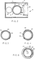
- FIG. 3 A second embodiment of a discharge lamp in accordance with the present invention is shown in FIG. 3. Like elements in FIGS. 2 and 3 have the same reference numerals.
- a metal strip 50 is in contact with conductive coating 40 over all or a substantial portion of the length of the lamp envelope 22.
- the metal strip 50 provides a low impedance electrical contact to the conductive coating 40.
- the metal strip 50 is connected, as described below, to a reference potential, such as ground.
- the metal strip 50 may be deposited directly on conductive coating 40 and is positioned on the lamp envelope 22 to minimize blockage of useful light output.
- the metal strip 50 may have a minimum width that provides the desired impedance and may be positioned facing the opaque portion of the housing.
- the metal strip is aluminum and may be applied to the lamp envelope 22 by evaporation or painting.
- FIG. 4 A third embodiment of a discharge lamp in accordance with the present invention is shown in FIG. 4. Like elements in FIGS. 2 and 4 have the same reference numerals.
- a metal strip 54 provides a low impedance electrical contact to conductive coating 40 and is connected to a reference potential, such as ground.
- the metal strip 54 additionally functions as a reflective coating on lamp envelope 22 and defines an aperture 56 for emission of light from the discharge lamp.
- the metal strip 54 covers all of the lamp envelope 22 except aperture 56 and has a reflective inside surface, so that light generated within the discharge lamp is reflected through aperture 56.
- FIGS. 1 and 2 The electrical connections of the lamp assembly of FIGS. 1 and 2 are shown in the schematic diagram of FIG. 5.
- One output terminal of the ballast circuit 20 is connected through transformer 30 to electrode 24.
- the other output terminal of the ballast circuit 20 is connected to electrode 26 and to ground.
- the conductive silicone strip 44 which electrically contacts the conductive coating 40 over the length of lamp envelope 22, is electrically connected to ground.
- a step-up transformer may be required at each end of the discharge lamp 12. In this configuration, electrode 26 is not grounded, and a balanced voltage is applied to the discharge lamp 12.
- ballast circuit 20 is located remotely from the discharge lamp 12
- the terminals of the ballast circuit 20 are connected to electrodes 24 and 26 of discharge lamp 12 by coaxial cables 60 and 62, respectively.
- Coaxial cable 60 includes a center conductor 64 connected between one output terminal of ballast circuit 20 and electrode 24, and an outer conductor 66 that is grounded.
- Coaxial cable 62 includes a center conductor 68 that is connected between the other output terminal of ballast circuit 20 and electrode 26, and an outer conductor 70 that is grounded.
- the light-transmissive conductive coating 40 and silicone strip 44 are electrically connected to outer conductors 66 and 70 of coaxial cable 60 and 62, respectively, to provide substantially continuous RF shielding of the lamp assembly from the ballast circuit 20 to and including discharge lamp 12.
- the discharge lamp 12 may be energized with a balanced voltage as shown in FIG. 6 or may utilize a single-ended drive wherein one of the electrodes is grounded, as shown in FIG. 5.
- step-up transformers are located in ballast circuit 20, and the required starting and operating voltages are transmitted through coaxial cables 60 and 62 to discharge lamp 12.
- a step-up transformer may be mounted in close proximity to one or both electrodes of discharge lamp 12.
- a coaxial cable is connected between each step-up transformer and the remotely located ballast circuit.
- the ballast circuit 20 may be located in close proximity to the discharge lamp 12 or may be located remotely.
- An advantage of mounting the ballast circuit close to the discharge lamp is that lead lengths are minimized and RF shielding is easier.
- An advantage of remote location of the ballast circuit is that the ballast circuit can be used to energize two or more discharge lamps in different locations.
- practical considerations, such as available space may dictate remote location of the ballast circuit.
- the connections to the discharge lamp are preferably made by coaxial cable, with the outer conductor of the coaxial cable connected to the conductive coating on the discharge lamp to provide continuous RF shielding to the extent possible.
- step-up transformers may be connected to one or both electrodes of the discharge lamp, depending on whether a grounded or a balanced drive configuration is utilized.
- the step-up transformer or transformers may be located in the ballast circuit or, more preferably, are located in close proximity to the electrodes of the discharge lamp to which they are connected.
- the RF shielding is provided on the discharge lamp and the electrical connections to the ballast circuit.
- the ballast circuit is also shielded to reduce RF emissions.
- the silicone strip 44 can be replaced with metal strip 50 shown in FIG. 3 or metal strip 54 shown in FIG. 4.
- the conductive coating 40 has sufficiently high conductivity to provide effective RF shielding, the conductive coating alone can be utilized, with the conductive coating connected to a reference potential, such as ground, at one or both ends of the discharge lamp.
- the coaxial cable 60 includes center conductor 64, outer conductor 66, typically in the form of a braided wire, and an insulator 72 between center conductor 64 and outer conductor 66.
- the coaxial cable also includes an outer jacket 74 surrounding outer conductor 66.
- the center conductor 64 is electrically connected to electrode 24 by attaching it to the lead wire which extends from electrode 24 through lamp envelope 22.
- the connection between center conductor 74 and the lead wire is surrounded with an insulator 76 such as silicone.
- the conductive coating 40 on the outer surface of lamp envelope 22 is preferably connected to outer conductor 66 by a conductive silicone tube 80.
- the conductive coating 40 preferably covers the main portion of lamp envelope 22 except for a seal region 82 near the electrode leads and preferably extends at least slightly beyond the electrode 24 toward seal region 82.
- the conductive silicone tube 80 provides a nonabrasive and reliable electrical connection to conductive coating 40.
- the silicone tube 80 is in electrical contact with both the conductive coating 40 and the metal or silicone strip.
- the silicone tube 80 in its unstretched state, is smaller in diameter than lamp envelope 22.
- the silicone tube 80 is stretched to a larger diameter to place it over lamp envelope 22, and the resilience of silicone tube 80 provides secure electrical contact with the conductive coating 40 and any metal or silicone strip that may be present on lamp envelope 22.
- the silicone tube 80 may be positioned inside the outer conductor 66 of coaxial cable 60, as shown in FIG. 7, or may be positioned outside outer conductor 66.
- the outer conductor 66 and the silicone tube may be secured in electrical contact by a heat shrinkable tube 84.
- a heat shrinkable tube may also be used to secure the silicone tube 80 in electrical contact with conductive coating 40.
- the configuration shown in FIG. 7 and described above provides a continuous RF shield around the lamp envelope 22, through the silicone tube 80 and the outer conductor 66 of coaxial cable 60 to the ballast circuit, thus providing substantial attenuation of RF noise.
- FIG. 8 A cross section of the assembly of FIG. 7 through the electrode 24 is shown in FIG. 8.
- the conductive coating 40 is surrounded by conductive silicone tube 80, thus providing a large area, nonabrasive electrical contact.
- a metal strip 86 is provided along the length of lamp envelope 22.
- the silicone tube 80 makes electrical contact with metal strip 86, thus providing a low impedance contact to the conductive coating 40 along the length of the lamp envelope 22.
- the conductive tube 80 provides a reliable, nonabrasive, large area electrical contact to the conductive coating 40.
- the silicone tube 80 is resilient and can be used for shock resistant mounting of the discharge lamp 12.
- the silicone tube 80 as well as the silicone strip 44 conduct heat from the discharge lamp.
- the ITO conductive coating on the lamp envelope provides a shield to reduce RF noise emission and is oxidation and abrasion resistant.
- FIG. 9 An alternative configuration for connecting the coaxial cable to the discharge lamp is shown in FIG. 9. Like elements in FIGS. 8 and 9 have the same reference numerals.
- the center conductor 64 of coaxial cable 60 is connected to electrode 24 as described above.
- the outer conductor 66 of coaxial cable 60 is in direct contact with conductive coating 40.
- the connection between coaxial cable 60 and discharge lamp 12 is secured by a heat shrinkable tube 90 which maintains electrical contact between outer conductor 66 and conductive coating 40.
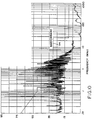
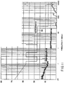
- FIGS. 10 and 11 are graph of RF emission level as a function of frequency.
- FIG. 10 illustrates the RF emission from an 18 inch neon lamp without a conductive coating operated at 3000 volts and 60 kHz (30 watts system power).
- FIG. 11 illustrates the RF emission from a neon lamp operated in the same manner having an indium tin oxide coating and a metal coating which defines an aperture, as shown in FIG. 4. The RF emission levels were measured in a certified testing laboratory.
- a line 94 represents a specification for a maximum acceptable level of RF emission over the frequency range.
- the neon lamp without a conductive coating exceeds the specification significantly.
- the neon lamp having a conductive coating meets the specification over the entire frequency range, as shown in FIG. 11.
- the light-transmissive conductive coating and/or the metal or silicone strip that contacts the conductive coating may be used as a heater for fluorescent lamps that may be subjected to low temperatures.
- a subminiature fluorescent lamp 110 is provided with a light-transmissive conductive coating 112, such as ITO, and a conductive strip 114, such as a metal strip or a conductive silicone strip.
- the electrode leads of the fluorescent lamp 110 are connected to a ballast circuit 116 which supplies electrical energy for lamp operation.
- the conductive strip 114 is connected at one end to ground and is connected at the other end through a thermal switch 120 to a DC source 122. Insulators 124 and 126, shown schematically in FIG. 12, isolate the voltage applied to fluorescent lamp 112 by ballast circuit 116 from the DC voltage applied to conductive strip 114.
- the thermal switch 120 may be positioned to sense the temperature of fluorescent lamp 112. When the temperature of the fluorescent lamp 112 is below a predetermined temperature, thermal switch 120 closes and connects DC source 122 to the conductive strip 114. When the thermal switch 120 is closed, an electrical current passes through conductive strip 114 and conductive coating 112, thereby heating fluorescent lamp 110. When the fluorescent lamp 110 is heated above the predetermined temperature or the ambient temperature is above the predetermined temperature, the thermal switch 120 opens, thereby discontinuing heating of fluorescent lamp 112.
- the heating of fluorescent lamp 112 is produced by the electrical resistance of conductive strip 114 and conductive coating 112.
- the resistance is selected based on the voltage of DC source 122, the length and diameter of fluorescent lamp 112, the expected minimum temperature and the desired power level.
- a 4 inch fluorescent lamp can be heated at a power level of 3.5 watts, a voltage of 12.8 volts and a resistance of conductive strip 114 of about 40-50 ohms.
- the resistance value required for heating is sufficiently low to provide effective RF shielding.
- the conductive strip 114 and the conductive coating 112 are connected to ground whether the thermal switch 120 is open or closed.
- the conductive coating 112 and the conductive strip 114 provide effective RF shielding of the fluorescent lamp 112, as well as heating of fluorescent lamp 112.
- the conductive coating 112 and the conductive strip 114 provide more efficient transfer of heat to fluorescent lamp 112 than the prior art printed circuit heater.
- the conductive coating 112 assists in the transfer of heat around the diameter of the lamp. Thus, there are no cold spots for mercury to recondense within the fluorescent lamp. For a 4 inch fluorescent lamp at -40°C, 50% of full light output was achieved in less than 20 seconds using a conductive strip powered at about 3.5 watts. This was less than one third of the power required for heating of the same lamp with the prior art printed circuit heater.
- circuit configurations can be used for heating fluorescent lamp 112 by passing an electrical current through the conductive strip 114 and the conductive coating 112.
- various types of thermal switches and other control circuits may be utilized.
- Sensing of lamp performance may be utilized as an alternative to sensing of lamp temperature.
Landscapes
- Engineering & Computer Science (AREA)
- General Engineering & Computer Science (AREA)
- Vessels And Coating Films For Discharge Lamps (AREA)
- Circuit Arrangements For Discharge Lamps (AREA)
- Discharge Lamps And Accessories Thereof (AREA)
- Formation Of Various Coating Films On Cathode Ray Tubes And Lamps (AREA)
Applications Claiming Priority (2)
| Application Number | Priority Date | Filing Date | Title |
|---|---|---|---|
| US08/537,513 US5702179A (en) | 1995-10-02 | 1995-10-02 | Discharge lamp having light-transmissive conductive coating for RF containment and heating |
| US537513 | 1995-10-02 |
Publications (3)
| Publication Number | Publication Date |
|---|---|
| EP0767340A2 true EP0767340A2 (de) | 1997-04-09 |
| EP0767340A3 EP0767340A3 (de) | 1998-12-16 |
| EP0767340B1 EP0767340B1 (de) | 2003-07-09 |
Family
ID=24142959
Family Applications (1)
| Application Number | Title | Priority Date | Filing Date |
|---|---|---|---|
| EP96115511A Expired - Lifetime EP0767340B1 (de) | 1995-10-02 | 1996-09-27 | Lampenanordnung mit einer Entladungslampe, die eine lichtdurchlässige und leitfähige Beschichtung zur RF-Begrenzung und Aufwärmung besitzt. |
Country Status (8)
| Country | Link |
|---|---|
| US (1) | US5702179A (de) |
| EP (1) | EP0767340B1 (de) |
| JP (1) | JPH09120796A (de) |
| KR (1) | KR970023603A (de) |
| CN (1) | CN1091942C (de) |
| CA (1) | CA2186921C (de) |
| DE (1) | DE69628986T2 (de) |
| HU (1) | HU217755B (de) |
Cited By (8)
| Publication number | Priority date | Publication date | Assignee | Title |
|---|---|---|---|---|
| EP0895021A3 (de) * | 1997-07-02 | 2000-01-05 | Osram Sylvania Inc. | Röhrenförmige Lampe und Reflektor-Einheit |
| EP0895274A4 (de) * | 1996-04-19 | 2000-02-23 | Sharp Kk | Beleuchtungsvorrichtung und anzeige unter verwendung derselben |
| EP0991107A1 (de) * | 1998-09-29 | 2000-04-05 | Patent-Treuhand-Gesellschaft für elektrische Glühlampen mbH | Entladungslampe und Beleuchtungssystem mit einer Entladungslampe |
| EP1167871A3 (de) * | 2000-06-27 | 2003-08-13 | Osram Sylvania Inc. | Leuchte und Leuchtenanordnung |
| WO2004083900A3 (en) * | 2003-03-18 | 2004-11-04 | Philips Intellectual Property | Gas discharge lamp |
| FR2905032A1 (fr) * | 2006-08-21 | 2008-02-22 | Saint Gobain | Structure lumineuse et/ou uv sensiblement plane |
| CN101124655B (zh) * | 2005-02-22 | 2011-03-16 | 法国圣-戈班玻璃公司 | 平板状或大致平板状发光结构 |
| EP2743964A3 (de) * | 2012-12-11 | 2015-02-11 | General Electric Company | Resistive Dünnschichtheizung einer Leuchtstofflampe |
Families Citing this family (51)
| Publication number | Priority date | Publication date | Assignee | Title |
|---|---|---|---|---|
| US6222318B1 (en) * | 1998-03-09 | 2001-04-24 | U.S. Philips Corporation | Low-pressure mercury vapor discharge lamp |
| US6242871B1 (en) * | 1998-05-12 | 2001-06-05 | Rui Ihu Ge | High field effect neon lamp |
| US6247830B1 (en) * | 1998-07-29 | 2001-06-19 | Russell Winnett | Heat shield for agricultural light bulb |
| KR100464709B1 (ko) * | 2001-03-12 | 2005-01-06 | 가부시키가이샤 고이토 세이사꾸쇼 | 방전 램프 장치 |
| EP1632985B1 (de) * | 2004-09-07 | 2014-06-25 | OSRAM GmbH | Hochdruckentladungslampe |
| US7642719B2 (en) * | 2005-04-12 | 2010-01-05 | General Electric Company | Energy efficient fluorescent lamp having an improved starting assembly and preferred method for manufacturing |
| US20060273731A1 (en) * | 2005-06-06 | 2006-12-07 | Tbt Asset Management International Limited | High Power Cold Cathode Tubular Fluorescent Lamp |
| JP2007012542A (ja) * | 2005-07-04 | 2007-01-18 | Matsushita Electric Ind Co Ltd | 閃光放電管及びストロボ装置 |
| ES2376350T3 (es) * | 2005-07-20 | 2012-03-13 | Tbt Asset Management International Limited | Unidad de iluminación con l�?mpara fluorescente de c�?todo fr�?o de forma serpentina. |
| US7378797B2 (en) * | 2005-12-16 | 2008-05-27 | General Electric Company | Fluorescent lamp with conductive coating |
| US20070247850A1 (en) * | 2006-03-28 | 2007-10-25 | Kenall Manufacturing Co. | Lighting Fixture with EMI/RFI Shield |
| USD544984S1 (en) | 2006-04-17 | 2007-06-19 | Ip Holdings, Llc | Air-cooled metallic tubular horticulture light fixture |
| US7530702B2 (en) * | 2006-05-12 | 2009-05-12 | Visteon Global Technologies, Inc. | Display over gage instrument cluster |
| JP5117774B2 (ja) * | 2007-06-28 | 2013-01-16 | 浜松ホトニクス株式会社 | 光源装置、放電ランプ及びその制御方法 |
| US7973489B2 (en) * | 2007-11-02 | 2011-07-05 | Tbt Asset Management International Limited | Lighting system for illumination using cold cathode fluorescent lamps |
| US8492991B2 (en) * | 2007-11-02 | 2013-07-23 | Tbt Asset Management International Limited | Lighting fixture system for illumination using cold cathode fluorescent lamps |
| EP2383770B1 (de) * | 2009-01-26 | 2014-11-05 | Panasonic Corporation | Stromentladungsrohr, verfahren zur formung eines reflektierenden films für das stromentladungsrohr und lichtemittierende vorrichtung |
| TWI417474B (zh) * | 2010-05-31 | 2013-12-01 | 明志科技大學 | 可降低電磁輻射的燈泡與燈具 |
| JP5236837B2 (ja) * | 2010-12-16 | 2013-07-17 | パナソニック株式会社 | 照明光源及び照明装置 |
| US9335038B2 (en) | 2011-07-20 | 2016-05-10 | Ip Holdings, Llc | Vertically disposed HID lamp fixture |
| USD770079S1 (en) | 2015-04-02 | 2016-10-25 | Ip Holdings, Llc | Light fixture |
| USD698986S1 (en) | 2013-03-27 | 2014-02-04 | Ip Holdings, Llc | Horticulture grow light housing |
| USD698987S1 (en) | 2013-06-20 | 2014-02-04 | Ip Holdings, Llc | Horticulture grow light housing |
| USD745993S1 (en) | 2013-07-09 | 2015-12-22 | Ip Holdings, Llc | Horticulture grow light housing |
| US9016907B2 (en) | 2013-07-18 | 2015-04-28 | Ip Holdings, Llc | Air cooled horticulture lighting fixture for a double ended high pressure sodium lamp |
| US9750199B2 (en) | 2013-07-18 | 2017-09-05 | Ip Holdings, Llc | Air cooled horticulture lighting fixture |
| USD748849S1 (en) | 2014-06-11 | 2016-02-02 | Ip Holdings, Llc | Sealed optics air cooled grow light |
| USD731701S1 (en) | 2014-02-24 | 2015-06-09 | Ip Holdings, Llc | Horticulture grow light housing |
| TR201408916A2 (tr) * | 2014-07-25 | 2016-02-22 | Bsh Ev Aletleri San Ve Tic As | Bir elektrik iletim elemanına sahip bir pişirici cihaz. |
| USD732235S1 (en) | 2014-08-07 | 2015-06-16 | Ip Holdings, Llc | Horticulture grow light |
| USD732236S1 (en) | 2014-09-11 | 2015-06-16 | Ip Holdings, Llc | Light fixture |
| USD747029S1 (en) | 2014-10-22 | 2016-01-05 | Ip Holdings, Llc | Horticulture grow light |
| USD751245S1 (en) | 2014-12-11 | 2016-03-08 | Ip Holdings, Llc | Horticulture grow light |
| USD757346S1 (en) | 2015-01-08 | 2016-05-24 | Ip Holdings, Llc | Horticulture grow light |
| USD773107S1 (en) | 2015-04-13 | 2016-11-29 | Ip Holdings, Llc | Horticulture grow light |
| USD769513S1 (en) | 2015-04-15 | 2016-10-18 | Ip Holdings, Llc | Light fixture |
| USD770670S1 (en) | 2015-06-24 | 2016-11-01 | Ip Holdings, Llc | Horticulture grow light |
| USD780985S1 (en) | 2016-01-05 | 2017-03-07 | Ip Holdings, Llc | Light fixture |
| USD780986S1 (en) | 2016-01-07 | 2017-03-07 | Ip Holdings, Llc | Light fixture |
| USD796728S1 (en) | 2016-06-06 | 2017-09-05 | Ip Holdings, Llc | Light fixture |
| USD804078S1 (en) | 2016-08-31 | 2017-11-28 | Ip Holdings, Llc | Light fixture |
| USD804079S1 (en) | 2016-08-31 | 2017-11-28 | Ip Holdings, Llc | Light fixture |
| USD797350S1 (en) | 2016-11-01 | 2017-09-12 | Ip Holdings, Llc | Light fixture |
| USD822882S1 (en) | 2017-05-17 | 2018-07-10 | Ip Holdings, Llc | Horticulture grow light |
| USD843049S1 (en) | 2017-09-14 | 2019-03-12 | Hgci, Inc. | Horticulture grow light |
| USD842532S1 (en) | 2017-10-25 | 2019-03-05 | Hgci, Inc. | Light fixture |
| USD871654S1 (en) | 2017-10-30 | 2019-12-31 | Hgci, Inc. | Light fixture |
| USD848663S1 (en) | 2017-11-03 | 2019-05-14 | Hgci, Inc. | Light fixture |
| USD848664S1 (en) | 2017-11-07 | 2019-05-14 | Hgci, Inc. | Light fixture |
| USD848665S1 (en) | 2017-11-08 | 2019-05-14 | Hgci, Inc. | Horticulture grow light |
| CN110150969A (zh) * | 2019-06-11 | 2019-08-23 | 杭州老板电器股份有限公司 | 蒸汽烹饪器具用防冷凝灯罩及蒸汽烹饪器 |
Family Cites Families (39)
| Publication number | Priority date | Publication date | Assignee | Title |
|---|---|---|---|---|
| US1839499A (en) * | 1928-11-26 | 1932-01-05 | Stewart Warner Corp | Vehicle signal device |
| US1792599A (en) * | 1929-04-11 | 1931-02-17 | R M Company Inc | Neon-light direction signal |
| US1854654A (en) * | 1931-06-08 | 1932-04-19 | Jr Louis A Koch | Electric sign |
| US3067356A (en) * | 1960-04-06 | 1962-12-04 | Sylvania Electric Prod | Fluorescent lamp |
| US3587167A (en) * | 1969-01-27 | 1971-06-28 | Sierracin Corp | Method of shielding of fluorescent lighting fixtures |
| US3609293A (en) * | 1969-08-01 | 1971-09-28 | Ppg Industries Inc | Electrically heated multiple glazed window |
| US3717781A (en) * | 1969-09-19 | 1973-02-20 | Sylvania Electric Prod | Aperture fluorescent lamp having uniform surface brightness |
| US3801808A (en) * | 1973-01-31 | 1974-04-02 | Gte Sylvania Inc | Light source with rf interference shield |
| US3885150A (en) * | 1973-12-03 | 1975-05-20 | John Ott Lab | Shielded luminaire |
| US3963954A (en) * | 1974-11-25 | 1976-06-15 | Gte Sylvania Incorporated | Fluorescent lamp having indium oxide conductive coating and a protective coating therefor |
| US3967153A (en) * | 1974-11-25 | 1976-06-29 | Gte Sylvania Incorporated | Fluorescent lamp having electrically conductive coating and a protective coating therefor |
| US4020385A (en) * | 1976-08-09 | 1977-04-26 | Gte Sylvania Incorporated | Fluorescent lamp having conductive film and protective film therefor |
| US4080545A (en) * | 1976-12-27 | 1978-03-21 | Xerox Corporation | Sodium vapor lamp with emission aperture |
| US4500810A (en) * | 1980-11-25 | 1985-02-19 | North American Philips Lighting Corporation | Fluorescent lamp having integral light-filtering means and starting aid |
| DE3306103C2 (de) * | 1982-04-26 | 1985-09-12 | Yamamoto Kogaku Co., Ltd., Higashi-Osaka, Osaka | Vorrichtung zum Beheizen des ein Sichtfenster eines Schutzhelmes abdeckenden Schutzglases |
| NL8205025A (nl) * | 1982-12-29 | 1984-07-16 | Philips Nv | Gasontladingslamp. |
| GB2142621B (en) * | 1983-06-17 | 1987-03-18 | Glaverbel | Coating hot glass with metals or metal compounds especially oxides |
| HUT39030A (en) * | 1984-07-30 | 1986-07-28 | Tungsram Reszvenytarsasag | High-pressure sodium lamp |
| NL8500738A (nl) * | 1985-03-14 | 1986-10-01 | Philips Nv | Elektrodeloze lagedrukontladingslamp. |
| JPS628134A (ja) * | 1985-07-05 | 1987-01-16 | Casio Comput Co Ltd | 光源装置 |
| US4792725A (en) * | 1985-12-10 | 1988-12-20 | The United States Of America As Represented By The Department Of Energy | Instantaneous and efficient surface wave excitation of a low pressure gas or gases |
| US4682146A (en) * | 1986-01-13 | 1987-07-21 | Friedman Iii Harry | Automotive indicator system |
| US5317132A (en) * | 1986-03-24 | 1994-05-31 | Ensci, Inc. | Heating elements containing electrically conductive tin oxide containing coatings |
| DE3626460A1 (de) * | 1986-08-05 | 1988-02-11 | Lehmann & Voss & Co | Kunststoffmischung mit elektromagnetischen abschirmeigenschaften |
| CA1272754A (en) * | 1986-10-22 | 1990-08-14 | Leo M. Sprengers | Sodium discharge lamp having a current supply conductor connected via a capacitor to a translucent conducting coating |
| US4924141A (en) * | 1986-11-12 | 1990-05-08 | Gte Products Corporation | Aluminum oxide reflector layer for fluorescent lamps |
| US4767969A (en) * | 1987-05-26 | 1988-08-30 | Honeywell, Inc. | RF emission shield for CRT displays |
| US4970376A (en) * | 1987-12-22 | 1990-11-13 | Gte Products Corporation | Glass transparent heater |
| US5013966A (en) * | 1988-02-17 | 1991-05-07 | Mitsubishi Denki Kabushiki Kaisha | Discharge lamp with external electrodes |
| US4956573A (en) * | 1988-12-19 | 1990-09-11 | Babcock Display Products, Inc. | Gas discharge display device with integral, co-planar, built-in heater |
| US5287258A (en) * | 1990-04-04 | 1994-02-15 | Robert Bosch Gmbh | Headlamp for motor vehicles |
| US5119467A (en) * | 1990-08-02 | 1992-06-02 | Air-Shields, Inc. | Transparent film radiant heat source for use with incubators |
| US5239238A (en) * | 1991-05-08 | 1993-08-24 | U.S. Philips Corporation | Electrodeless low-pressure mercury vapour discharge lamp |
| US5354966A (en) * | 1991-12-02 | 1994-10-11 | Sperbeck Scott W | Window defogging system with optically clear overlay having multi-layer silver bus bars and electrically isolating peripheral grooves |
| JP2797804B2 (ja) * | 1992-01-09 | 1998-09-17 | 日本電気株式会社 | バックライト及び液晶表示装置 |
| US5397966A (en) * | 1992-05-20 | 1995-03-14 | Diablo Research Corporation | Radio frequency interference reduction arrangements for electrodeless discharge lamps |
| JPH0629002A (ja) * | 1992-07-08 | 1994-02-04 | Ise Electronics Corp | 放電管 |
| GB9326123D0 (en) * | 1993-12-22 | 1994-02-23 | Ge Lighting Ltd | Electrodeless fluorescent lamp |
| GB9405371D0 (en) * | 1994-03-18 | 1994-05-04 | Ge Lighting Ltd | Electrodeless fluorescent lamp |
-
1995
- 1995-10-02 US US08/537,513 patent/US5702179A/en not_active Expired - Fee Related
-
1996
- 1996-09-27 EP EP96115511A patent/EP0767340B1/de not_active Expired - Lifetime
- 1996-09-27 DE DE69628986T patent/DE69628986T2/de not_active Expired - Fee Related
- 1996-09-28 CN CN96122825A patent/CN1091942C/zh not_active Expired - Fee Related
- 1996-10-01 HU HU9602702A patent/HU217755B/hu not_active IP Right Cessation
- 1996-10-01 CA CA002186921A patent/CA2186921C/en not_active Expired - Fee Related
- 1996-10-02 JP JP8262104A patent/JPH09120796A/ja active Pending
- 1996-10-02 KR KR1019960043624A patent/KR970023603A/ko not_active Ceased
Cited By (13)
| Publication number | Priority date | Publication date | Assignee | Title |
|---|---|---|---|---|
| EP0895274A4 (de) * | 1996-04-19 | 2000-02-23 | Sharp Kk | Beleuchtungsvorrichtung und anzeige unter verwendung derselben |
| US6254244B1 (en) | 1996-04-19 | 2001-07-03 | Sharp Kabushiki Kaisha | Luminaire and display using the same |
| EP0895021A3 (de) * | 1997-07-02 | 2000-01-05 | Osram Sylvania Inc. | Röhrenförmige Lampe und Reflektor-Einheit |
| EP0991107A1 (de) * | 1998-09-29 | 2000-04-05 | Patent-Treuhand-Gesellschaft für elektrische Glühlampen mbH | Entladungslampe und Beleuchtungssystem mit einer Entladungslampe |
| US6153982A (en) * | 1998-09-29 | 2000-11-28 | Patent-Treuhand-Gesellschaft Fuer Elektrische Gluehlampen Mbh | Discharge lamp and lighting system having a discharge lamp |
| EP1167871A3 (de) * | 2000-06-27 | 2003-08-13 | Osram Sylvania Inc. | Leuchte und Leuchtenanordnung |
| WO2004083900A3 (en) * | 2003-03-18 | 2004-11-04 | Philips Intellectual Property | Gas discharge lamp |
| CN101124655B (zh) * | 2005-02-22 | 2011-03-16 | 法国圣-戈班玻璃公司 | 平板状或大致平板状发光结构 |
| FR2905032A1 (fr) * | 2006-08-21 | 2008-02-22 | Saint Gobain | Structure lumineuse et/ou uv sensiblement plane |
| WO2008023124A1 (fr) * | 2006-08-21 | 2008-02-28 | Saint-Gobain Glass France | Structure lumineuse et/ou uv sensiblement plane |
| US8120236B2 (en) | 2006-08-21 | 2012-02-21 | Saint-Gobain Glass France | Light-emitting structure having leakage current limited by an electrical conductor with an adjustable frequency and an adjustable potential |
| EP2743964A3 (de) * | 2012-12-11 | 2015-02-11 | General Electric Company | Resistive Dünnschichtheizung einer Leuchtstofflampe |
| US9117649B2 (en) | 2012-12-11 | 2015-08-25 | General Electric Company | Resistive thin layer heating of fluorescent lamp |
Also Published As
| Publication number | Publication date |
|---|---|
| DE69628986T2 (de) | 2004-05-13 |
| KR970023603A (ko) | 1997-05-30 |
| CA2186921C (en) | 2004-09-21 |
| HUP9602702A3 (en) | 1998-04-28 |
| EP0767340B1 (de) | 2003-07-09 |
| CA2186921A1 (en) | 1997-04-03 |
| CN1154566A (zh) | 1997-07-16 |
| HUP9602702A2 (en) | 1997-05-28 |
| HU217755B (hu) | 2000-04-28 |
| EP0767340A3 (de) | 1998-12-16 |
| US5702179A (en) | 1997-12-30 |
| DE69628986D1 (de) | 2003-08-14 |
| JPH09120796A (ja) | 1997-05-06 |
| CN1091942C (zh) | 2002-10-02 |
| HU9602702D0 (en) | 1996-11-28 |
Similar Documents
| Publication | Publication Date | Title |
|---|---|---|
| EP0767340B1 (de) | Lampenanordnung mit einer Entladungslampe, die eine lichtdurchlässige und leitfähige Beschichtung zur RF-Begrenzung und Aufwärmung besitzt. | |
| US4714986A (en) | Vehicular reflector-light source combination unit | |
| EP1606832B1 (de) | Gasentladungslampe | |
| EP0714000B1 (de) | Leuchte mit elastischen Verbindungselementen für eine genaue und schwingungsfreie Aufnahme einer Neonlampe | |
| JPH0746599B2 (ja) | 無電極低圧放電ランプ | |
| US6153982A (en) | Discharge lamp and lighting system having a discharge lamp | |
| KR20020093102A (ko) | 외부 전극형 형광 램프 | |
| US5710485A (en) | Neon lamp assembly with RF noise shield | |
| JP4409570B2 (ja) | ガス放電ランプ、ヘッドライト又は照明装置 | |
| US3801808A (en) | Light source with rf interference shield | |
| WO2008029369A1 (en) | Automotive lamp | |
| KR100228644B1 (ko) | 형광등 및 그 점등회로 | |
| JP3115673B2 (ja) | 自動車前照灯用メタルハライドランプ | |
| JP2001126663A (ja) | 高圧放電ランプ | |
| KR200216795Y1 (ko) | 차량용 아크 방전 램프 | |
| JPH07272872A (ja) | 放電灯点灯装置および照明装置 | |
| JPH10302983A (ja) | 無電極放電灯点灯装置 | |
| JP2002164183A (ja) | 高輝度放電灯 |
Legal Events
| Date | Code | Title | Description |
|---|---|---|---|
| PUAI | Public reference made under article 153(3) epc to a published international application that has entered the european phase |
Free format text: ORIGINAL CODE: 0009012 |
|
| 17P | Request for examination filed |
Effective date: 19961022 |
|
| AK | Designated contracting states |
Kind code of ref document: A2 Designated state(s): BE DE FR GB IT NL |
|
| PUAL | Search report despatched |
Free format text: ORIGINAL CODE: 0009013 |
|
| RHK1 | Main classification (correction) |
Ipc: H01J 61/35 |
|
| AK | Designated contracting states |
Kind code of ref document: A3 Designated state(s): BE DE FR GB IT NL |
|
| 17Q | First examination report despatched |
Effective date: 20000426 |
|
| GRAG | Despatch of communication of intention to grant |
Free format text: ORIGINAL CODE: EPIDOS AGRA |
|
| RTI1 | Title (correction) |
Free format text: LAMP ASSEMBLY CONTAINING A DISCHARGE LAMP HAVING A LIGHT-TRANSMISSIVE CONDUCTIVE COATING FOR RF CONTAINMENT AND HEATING |
|
| GRAG | Despatch of communication of intention to grant |
Free format text: ORIGINAL CODE: EPIDOS AGRA |
|
| GRAG | Despatch of communication of intention to grant |
Free format text: ORIGINAL CODE: EPIDOS AGRA |
|
| GRAH | Despatch of communication of intention to grant a patent |
Free format text: ORIGINAL CODE: EPIDOS IGRA |
|
| GRAH | Despatch of communication of intention to grant a patent |
Free format text: ORIGINAL CODE: EPIDOS IGRA |
|
| GRAA | (expected) grant |
Free format text: ORIGINAL CODE: 0009210 |
|
| RIC1 | Information provided on ipc code assigned before grant |
Ipc: 7F 21S 8/10 B Ipc: 7H 01J 61/04 B Ipc: 7H 01B 1/04 B Ipc: 7B 60Q 3/00 B Ipc: 7B 60Q 1/26 B Ipc: 7H 01J 61/70 B Ipc: 7H 01J 61/52 B Ipc: 7H 01J 61/56 B Ipc: 7H 01J 61/35 A |
|
| AK | Designated contracting states |
Designated state(s): BE DE FR GB IT NL |
|
| REG | Reference to a national code |
Ref country code: GB Ref legal event code: FG4D |
|
| REF | Corresponds to: |
Ref document number: 69628986 Country of ref document: DE Date of ref document: 20030814 Kind code of ref document: P |
|
| PLBE | No opposition filed within time limit |
Free format text: ORIGINAL CODE: 0009261 |
|
| STAA | Information on the status of an ep patent application or granted ep patent |
Free format text: STATUS: NO OPPOSITION FILED WITHIN TIME LIMIT |
|
| ET | Fr: translation filed | ||
| 26N | No opposition filed |
Effective date: 20040414 |
|
| PGFP | Annual fee paid to national office [announced via postgrant information from national office to epo] |
Ref country code: GB Payment date: 20070910 Year of fee payment: 12 |
|
| PGFP | Annual fee paid to national office [announced via postgrant information from national office to epo] |
Ref country code: NL Payment date: 20070913 Year of fee payment: 12 Ref country code: IT Payment date: 20070926 Year of fee payment: 12 Ref country code: DE Payment date: 20071122 Year of fee payment: 12 Ref country code: BE Payment date: 20070918 Year of fee payment: 12 |
|
| PGFP | Annual fee paid to national office [announced via postgrant information from national office to epo] |
Ref country code: FR Payment date: 20070918 Year of fee payment: 12 |
|
| BERE | Be: lapsed |
Owner name: *OSRAM SYLVANIA INC. Effective date: 20080930 |
|
| GBPC | Gb: european patent ceased through non-payment of renewal fee |
Effective date: 20080927 |
|
| PG25 | Lapsed in a contracting state [announced via postgrant information from national office to epo] |
Ref country code: NL Free format text: LAPSE BECAUSE OF NON-PAYMENT OF DUE FEES Effective date: 20090401 |
|
| NLV4 | Nl: lapsed or anulled due to non-payment of the annual fee |
Effective date: 20090401 |
|
| REG | Reference to a national code |
Ref country code: FR Ref legal event code: ST Effective date: 20090529 |
|
| PG25 | Lapsed in a contracting state [announced via postgrant information from national office to epo] |
Ref country code: BE Free format text: LAPSE BECAUSE OF NON-PAYMENT OF DUE FEES Effective date: 20080930 |
|
| PG25 | Lapsed in a contracting state [announced via postgrant information from national office to epo] |
Ref country code: IT Free format text: LAPSE BECAUSE OF NON-PAYMENT OF DUE FEES Effective date: 20080927 Ref country code: DE Free format text: LAPSE BECAUSE OF NON-PAYMENT OF DUE FEES Effective date: 20090401 |
|
| PG25 | Lapsed in a contracting state [announced via postgrant information from national office to epo] |
Ref country code: FR Free format text: LAPSE BECAUSE OF NON-PAYMENT OF DUE FEES Effective date: 20080930 |
|
| PG25 | Lapsed in a contracting state [announced via postgrant information from national office to epo] |
Ref country code: GB Free format text: LAPSE BECAUSE OF NON-PAYMENT OF DUE FEES Effective date: 20080927 |