EP0767366A1 - Rotierender Spindelantrieb mit Schnellspannvorrichtung und Maschine damit - Google Patents
Rotierender Spindelantrieb mit Schnellspannvorrichtung und Maschine damit Download PDFInfo
- Publication number
- EP0767366A1 EP0767366A1 EP96402064A EP96402064A EP0767366A1 EP 0767366 A1 EP0767366 A1 EP 0767366A1 EP 96402064 A EP96402064 A EP 96402064A EP 96402064 A EP96402064 A EP 96402064A EP 0767366 A1 EP0767366 A1 EP 0767366A1
- Authority
- EP
- European Patent Office
- Prior art keywords
- control rod
- spindle
- rotation
- bearings
- hollow shaft
- Prior art date
- Legal status (The legal status is an assumption and is not a legal conclusion. Google has not performed a legal analysis and makes no representation as to the accuracy of the status listed.)
- Withdrawn
Links
- 238000005259 measurement Methods 0.000 claims description 5
- 230000003993 interaction Effects 0.000 claims description 4
- 238000006073 displacement reaction Methods 0.000 claims description 3
- 230000006835 compression Effects 0.000 description 3
- 238000007906 compression Methods 0.000 description 3
- 210000000078 claw Anatomy 0.000 description 2
- 238000000034 method Methods 0.000 description 1
- 230000004048 modification Effects 0.000 description 1
- 238000012986 modification Methods 0.000 description 1
- BASFCYQUMIYNBI-UHFFFAOYSA-N platinum Chemical compound [Pt] BASFCYQUMIYNBI-UHFFFAOYSA-N 0.000 description 1
- 230000009897 systematic effect Effects 0.000 description 1
Images

Classifications
-
- G—PHYSICS
- G01—MEASURING; TESTING
- G01M—TESTING STATIC OR DYNAMIC BALANCE OF MACHINES OR STRUCTURES; TESTING OF STRUCTURES OR APPARATUS, NOT OTHERWISE PROVIDED FOR
- G01M1/00—Testing static or dynamic balance of machines or structures
- G01M1/02—Details of balancing machines or devices
- G01M1/04—Adaptation of bearing support assemblies for receiving the body to be tested
- G01M1/045—Adaptation of bearing support assemblies for receiving the body to be tested the body being a vehicle wheel
Definitions
- the invention relates to a fast-mounting rotary drive spindle, of the type comprising a hollow shaft rotatably mounted on two spaced bearings and carrying at a first end a means for launching and driving in rotation and at the second end a mounting flange determining a reference plane and holding a body driven in rotation; a control rod passing through said hollow shaft and movable between two positions, the first of which corresponds to the joining of said body with the drive shaft in rotation and the second of which corresponds to the release of said body.
- the invention is particularly useful for balancing vehicle wheels and measuring the physical parameters necessary for this purpose.
- the invention also relates to a machine, such as a balancer equipped with a rotary drive spindle according to the invention.
- Document US 4 202 213 relates to an apparatus for automatically locking motor vehicle wheels on balancing machines.
- This device is generally satisfactory but has the drawback that the crew driven in rotation is relatively large and in particular comprises all or part of a pneumatic locking control cylinder actuating a control rod.
- this device When the compressed air supply is cut, this device offers no security and automatically unlocks the wheel rim, which is likely to cause accidents to personnel and damage to equipment.
- the invention aims to remedy the drawbacks of the known technique, by creating a new quick-mounting spindle, usable in any type of machine and particularly useful as a component of a balancer, ensuring the safety of personnel and providing good quality. of measurement.
- the subject of the invention is a fast-mounting rotary drive spindle, in particular for mounting and maintaining a wheel to be balanced on a balancing machine, of the type comprising a hollow shaft rotatably mounted on two spaced bearings and carrying a first end means for launching and driving in rotation and at the second end a mounting flange determining a reference plane and holding the rim of the wheel to be balanced or of a body driven in rotation; a control rod passing through said hollow shaft and movable between two positions, the first of which corresponds to the displacement of a locking means for the rim or of the body on said mounting flange and the second corresponds to the erasure of said locking means and to release of the rim or body; a first prestressed elastic means provided for permanently applying the control rod in the first locking position and a second means provided for acting against said first means and pushing the control rod into the second unlocking position, characterized in that that the second means is mounted relative to the hollow drive shaft and to the control rod in an arrangement similar to that of a
- the invention also relates to a machine or balancer comprising a spindle according to any one of the preceding claims, characterized in that the balancer comprises: on the one hand, a fixed plate carrying the two spaced bearings on which is mounted rotation an assembly comprising the hollow shaft, the control rod, the first prestressed elastic means and the deployable locking means and, on the other hand, a support on which said second means is mounted.
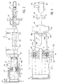
- Figure 1 shows schematically a top view with partial radial sections of a spindle according to the invention in the unlocked position.
- FIG. 2 schematically represents a top view of a spindle according to the invention with radial sections in the locked position.
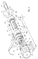
- FIG. 3 schematically represents a perspective view with partial cutaway of a spindle according to the invention.
- FIG. 4 schematically represents an enlarged partial view similar to FIG. 2 illustrating the operation of a spindle according to the invention.
- a balancing machine comprises a chassis making it possible to permanently fix a plate 1 by means of bolts 2, so as to support bearings 3a, 3b spaced apart from one another on which a rotary assembly described below is mounted for rotation.
- the chassis of the balancer also carries a support 4 constituted by a thick plate with a central bore 5.
- a pneumatic cylinder 6 is mounted captive in this bore 5 by means of a bushing 7 according to an arrangement providing a predetermined longitudinal sliding clearance, corresponding to the sum of the distances j 1 and j 2 (FIG. 1) or j 3 and j 4 (figure 2).
- the cylinder 6 is preferably a pneumatic cylinder, but could also be constituted by a hydraulic cylinder, an electric traction means or other equivalent mechanical means.
- the body of the jack 6 is integral with the sleeve 7 and carries a stirrup 8 having two end claws 8a, 8b.
- the actuator 6 is therefore mounted captive relative to the support 4 secured to the frame of the balancer in a floating assembly coaxial with the movable assembly able to be driven in rotation, so as not to be in contact with this driven movable assembly in rotation in the locking position corresponding to FIG. 2, and so as to operate on this movable assembly in the manner of a hub puller in the unlocking position corresponding to FIG. 1.
- the rod 6a of the jack presses on a control rod 9 passing through the hollow shaft 10 for rotational drive, while the stirrup 8 pulls on the disc 11 integral with the drive shaft for rotation by being taken for example between two nuts 12a and 12b.
- the movable assembly comprises a hollow shaft 10 carrying the disc 11 fixed by means of the nuts 12a and 12b, a means 12 for launching and driving in rotation of the pulley type or equivalent, a light 13 closed at its two ends serving as a guide to a stop 14 integral with the control rod 9, a mounting flange 15 determining a reference and holding plane of the rim of a wheel to be balanced or of a body driven in rotation, and another passageway 16 for the deployment of a locking means 17 consisting of two preloaded clamps in position opened by a spring.
- the whole of this mobile assembly is mounted in the rotary bearings 3a and 3b by means, for example, of ball bearings 18a and 18b.
- a spring 19 is placed between a conformation 20 or a shoulder integral with the hollow shaft 10 and the stop 14 integral with the control rod 9.
- the spring 19 is preferably a helical compression compression spring preloaded so as to push the stop 14 in the position of Figure 2 corresponding to the locking.
- the cylinder 6 is a spring return cylinder 6c supplied with compressed air by an electrically controlled distributor.
- the electrical signal of this command is used by a safety program or an equivalent electromechanical assembly preventing rotation of the drive shaft 10 when the jack 6 is supplied with compressed air to perform the unlocking.
- An electrical prohibition signal is provided to prevent unlocking during rotation of the drive shaft 10.
- the second means constituted by the jack 6 is mounted substantially co-axially with the control rod 9 according to a floating assembly, so as not to be in contact with the control rod 9 during the rotation of the mobile assembly. in the locked position ( Figure 2). Due to this floating assembly, the assembly comprising the actuator 6 and the stirrup 8 moves by itself when the mobile assembly is launched in rotation so as not to be in contact with the control rod 9 or the disc 11 of the rotary drive shaft 10.
- the entire device operates in a similar manner to that of a hub puller, by transmitting the traction force of the claws 8a, 8b of the caliper 8 on the disc 11 to the control rod 9 via the cylinder 6 when the latter is supplied with compressed air at a pressure sufficient to act against the prestressed spring 19 and to push the control rod 9 towards the unlocking position (FIG. 1).
- control rod 9 is facilitated by the fact that, opposite the end carrying the deployable locking means 17, there is simply a flat bearing surface 9a able to cooperate with the end of the rod 6a of the actuator 6.
- the bearing surface 9a is spaced from the rod 6a of the actuator 6 in the locking position of FIG. 2, which has the advantage of not transmitting any influence and any interaction coming from the frame or the actuator 6 susceptible to interfere with the spindle rotation movement or to distort the measurements made during the spindle rotation.
- the body of the jack 6 can be maintained in a position spaced from the movable assembly by suitable elastic means such as springs arranged on either side of the support 4, between the cylinder of the jack 6 and the base 8c of the caliper 8.
- suitable elastic means such as springs arranged on either side of the support 4, between the cylinder of the jack 6 and the base 8c of the caliper 8.
- the invention is particularly advantageous when applied to the balancing of vehicle wheels, but the application of the invention to any other kind of machine tool, drive machine, for launching a body in rotation turning does not depart from the scope of the present invention.
- the invention allows the replacement of an existing spindle with a spindle according to the invention due to the fact that the first elastic pre-stressed means 19 is integral with the rotation drive shaft 10, between the two spaced apart bearings 3a and 3b integral with the plate 2: the external diameter of the rotary drive shaft is therefore of the same order or equal to that of the rotary drive shafts of the balancing pins of the prior art, which allows a quick standard exchange in the case where the frames are fitted with identical or compatible fixing plates 1.
- the second means can be operated at the hand instead of calling on an external energy source; it is then a lever system, eccentric, connecting rod and crank or equivalent.
Landscapes
- Physics & Mathematics (AREA)
- General Physics & Mathematics (AREA)
- Testing Of Balance (AREA)
- Machine Tool Units (AREA)
Applications Claiming Priority (2)
| Application Number | Priority Date | Filing Date | Title |
|---|---|---|---|
| FR9511653A FR2739688B1 (fr) | 1995-10-04 | 1995-10-04 | Broche d'entrainement en rotation a montage rapide, et machine comportant une telle broche |
| FR9511653 | 1995-10-04 |
Publications (1)
| Publication Number | Publication Date |
|---|---|
| EP0767366A1 true EP0767366A1 (de) | 1997-04-09 |
Family
ID=9483220
Family Applications (1)
| Application Number | Title | Priority Date | Filing Date |
|---|---|---|---|
| EP96402064A Withdrawn EP0767366A1 (de) | 1995-10-04 | 1996-09-27 | Rotierender Spindelantrieb mit Schnellspannvorrichtung und Maschine damit |
Country Status (3)
| Country | Link |
|---|---|
| US (1) | US5777224A (de) |
| EP (1) | EP0767366A1 (de) |
| FR (1) | FR2739688B1 (de) |
Families Citing this family (7)
| Publication number | Priority date | Publication date | Assignee | Title |
|---|---|---|---|---|
| IT1287823B1 (it) * | 1996-09-06 | 1998-08-19 | Femas Srl | Dispositivo automatico di bloccaggio delle ruote di automezzi in genere sugli alberi delle macchine equilibratrici |
| IT1285485B1 (it) * | 1996-10-08 | 1998-06-08 | Carlo Buzzi | Dispositivo di bloccaggio automatico di ruote e simili su una macchina equilibratrice |
| DE10238271B4 (de) * | 2002-08-21 | 2012-11-08 | Snap-On Equipment Gmbh | Verfahren und Vorrichtung zum zentrierten Spannen eines Kraftfahrzeugrades auf eine Hauptwelle einer Radauswuchtmaschine |
| ITRE20020074A1 (it) * | 2002-10-02 | 2004-04-03 | Corghi Spa | Gruppo di bloccaggio e trascinamento di un corpo rotante, |
| DE10305714B4 (de) * | 2003-02-12 | 2014-04-30 | Bayerische Motoren Werke Aktiengesellschaft | Wuchtfutter |
| ITVR20060013A1 (it) * | 2006-01-19 | 2007-07-20 | Ravaglioli Spa | Dispositivo per bloccare-sbloccare ruote gommate di veicoli su un mandrino di una macchina di manutenzione. |
| GB2577275B (en) * | 2018-09-19 | 2022-06-29 | Universal Balancing Ltd | Apparatus for supporting a rotor during a balancing process |
Citations (3)
| Publication number | Priority date | Publication date | Assignee | Title |
|---|---|---|---|---|
| DE2813387A1 (de) * | 1977-03-29 | 1978-10-05 | Sice | Auswuchtmaschine fuer motorfahrzeugraeder |
| DE4000424A1 (de) * | 1990-01-09 | 1991-07-11 | Rohe Gmbh A | Spannvorrichtung zum zentrieren und aufspannen eines rotationskoerpers |
| EP0550816A2 (de) * | 1992-01-09 | 1993-07-14 | Hofmann Werkstatt-Technik Gmbh | Verfahren und Vorrichtung zum Spannen und Lösen eines Rotors an einer von einem Motor angetriebenen Hauptwelle einer Unwuchtmessanordnung |
-
1995
- 1995-10-04 FR FR9511653A patent/FR2739688B1/fr not_active Expired - Fee Related
-
1996
- 1996-09-27 EP EP96402064A patent/EP0767366A1/de not_active Withdrawn
- 1996-10-02 US US08/724,918 patent/US5777224A/en not_active Expired - Fee Related
Patent Citations (3)
| Publication number | Priority date | Publication date | Assignee | Title |
|---|---|---|---|---|
| DE2813387A1 (de) * | 1977-03-29 | 1978-10-05 | Sice | Auswuchtmaschine fuer motorfahrzeugraeder |
| DE4000424A1 (de) * | 1990-01-09 | 1991-07-11 | Rohe Gmbh A | Spannvorrichtung zum zentrieren und aufspannen eines rotationskoerpers |
| EP0550816A2 (de) * | 1992-01-09 | 1993-07-14 | Hofmann Werkstatt-Technik Gmbh | Verfahren und Vorrichtung zum Spannen und Lösen eines Rotors an einer von einem Motor angetriebenen Hauptwelle einer Unwuchtmessanordnung |
Also Published As
| Publication number | Publication date |
|---|---|
| FR2739688B1 (fr) | 1997-11-28 |
| US5777224A (en) | 1998-07-07 |
| FR2739688A1 (fr) | 1997-04-11 |
Similar Documents
| Publication | Publication Date | Title |
|---|---|---|
| FR2508359A1 (fr) | Porte-outil pour perceuses et perceuses a percussion | |
| FR2619453A1 (fr) | Procede pour coupler un module de detection sismique a la paroi d'un sondage et sonde pour sa mise en oeuvre | |
| FR2489019A1 (fr) | Dispositif d'assistance, notamment pour l'amplification de la force de freinage sur un vehicule automobile | |
| FR2644542A1 (fr) | Dispositif tendeur a reglage par ressort | |
| EP0008452A1 (de) | Betätigungsvorrichtung für Scheibenbremsen | |
| FR2605959A1 (fr) | Dispositif de freinage pour vehicule | |
| FR2638214A1 (fr) | Frein a disque et son mecanisme de reglage automatique | |
| FR2561616A1 (fr) | Dispositif d'actionnement a blocage automatique et ensemble d'actionnement comprenant deux dispositifs de ce type, en particulier pour l'aviation | |
| EP0767366A1 (de) | Rotierender Spindelantrieb mit Schnellspannvorrichtung und Maschine damit | |
| FR2838665A1 (fr) | Dispositif de vissage de bouchons | |
| EP0448021A1 (de) | Einrichtung zum Heben einer Last mittels zwei parallelen, synchron drehenden Trommeln | |
| FR2611837A1 (fr) | Dispositif de commande d'embrayage avec pilotage | |
| EP0856379A1 (de) | Schleifband Vorrichtung zum Bearbeiten einer cylindrischen Lageroberfläche eines Werkstückes | |
| EP0813951B1 (de) | Übertragungsring für Luftreifen oder für Luftreifengürtel | |
| FR2645643A1 (fr) | Dispositif pour appliquer une charge d'intensite et d'orientation determinees et reglables a au moins un roulement a bille associe a un arbre tournant | |
| FR2756916A1 (fr) | Appareil de mesure d'un jeu entre deux pieces | |
| EP0569288B1 (de) | Hubschrauberheckrotor mit einem Detektor der Überschreitung einer Verschiebungschwellenspannung in der Steigungsregelung | |
| EP1592534B1 (de) | Vorrichtung zum schleifen von ophthalmischen linsen mit verbessertem mittel zum festklemmen des glasrohlings zum schleifen | |
| EP0539249B1 (de) | Fahrzeug-Scheibenwischer, der Mittel aufweist, die gesteuert werden, um den Wischerdruck zu ändern | |
| FR2619214A1 (fr) | Appareil pour la detection du balourd d'une roue d'automobile en vue de l'equilibrage de celle-ci. | |
| EP0801232A1 (de) | Hydraulisches Steuerventil für Servosteuerung eines Luftfahrzeugs, insbesondere Hubschraubers | |
| EP4169779B1 (de) | Handbremssystem | |
| EP0586289B1 (de) | Fahrzeugachsenprüfeinrichtung | |
| FR2577638A1 (fr) | Appareil automatique de reglage pour frein a disque | |
| FR2658148A1 (fr) | Dispositif d'assistance de direction de vehicule automobile ou equivalent. |
Legal Events
| Date | Code | Title | Description |
|---|---|---|---|
| PUAI | Public reference made under article 153(3) epc to a published international application that has entered the european phase |
Free format text: ORIGINAL CODE: 0009012 |
|
| AK | Designated contracting states |
Kind code of ref document: A1 Designated state(s): DE ES GB IT |
|
| 17P | Request for examination filed |
Effective date: 19971004 |
|
| STAA | Information on the status of an ep patent application or granted ep patent |
Free format text: STATUS: THE APPLICATION IS DEEMED TO BE WITHDRAWN |
|
| 18D | Application deemed to be withdrawn |
Effective date: 19990401 |