EP0767367A1 - Verfahren und Vorrichtung zum Auswuchten eines rotierenden Körpers durch Anbringen von Ausgleichsgewichten - Google Patents
Verfahren und Vorrichtung zum Auswuchten eines rotierenden Körpers durch Anbringen von Ausgleichsgewichten Download PDFInfo
- Publication number
- EP0767367A1 EP0767367A1 EP96402065A EP96402065A EP0767367A1 EP 0767367 A1 EP0767367 A1 EP 0767367A1 EP 96402065 A EP96402065 A EP 96402065A EP 96402065 A EP96402065 A EP 96402065A EP 0767367 A1 EP0767367 A1 EP 0767367A1
- Authority
- EP
- European Patent Office
- Prior art keywords
- rotation
- rotating body
- laying
- balancing
- mass
- Prior art date
- Legal status (The legal status is an assumption and is not a legal conclusion. Google has not performed a legal analysis and makes no representation as to the accuracy of the status listed.)
- Granted
Links
- 238000000034 method Methods 0.000 title claims abstract description 21
- 230000000903 blocking effect Effects 0.000 claims description 10
- 230000033228 biological regulation Effects 0.000 claims description 2
- 208000031968 Cadaver Diseases 0.000 description 8
- 238000010586 diagram Methods 0.000 description 6
- 241001071861 Lethrinus genivittatus Species 0.000 description 3
- 238000004804 winding Methods 0.000 description 3
- 230000005540 biological transmission Effects 0.000 description 2
- 238000009434 installation Methods 0.000 description 2
- 230000010355 oscillation Effects 0.000 description 2
- 230000001105 regulatory effect Effects 0.000 description 2
- 229910000831 Steel Inorganic materials 0.000 description 1
- 238000004026 adhesive bonding Methods 0.000 description 1
- 230000001276 controlling effect Effects 0.000 description 1
- 238000001514 detection method Methods 0.000 description 1
- 239000006185 dispersion Substances 0.000 description 1
- 238000006073 displacement reaction Methods 0.000 description 1
- 230000000694 effects Effects 0.000 description 1
- 238000010438 heat treatment Methods 0.000 description 1
- 230000004048 modification Effects 0.000 description 1
- 238000012986 modification Methods 0.000 description 1
- 230000003287 optical effect Effects 0.000 description 1
- 238000005070 sampling Methods 0.000 description 1
- 239000010959 steel Substances 0.000 description 1
Images



Classifications
-
- G—PHYSICS
- G01—MEASURING; TESTING
- G01M—TESTING STATIC OR DYNAMIC BALANCE OF MACHINES OR STRUCTURES; TESTING OF STRUCTURES OR APPARATUS, NOT OTHERWISE PROVIDED FOR
- G01M1/00—Testing static or dynamic balance of machines or structures
- G01M1/14—Determining imbalance
- G01M1/16—Determining imbalance by oscillating or rotating the body to be tested
- G01M1/22—Determining imbalance by oscillating or rotating the body to be tested and converting vibrations due to imbalance into electric variables
- G01M1/225—Determining imbalance by oscillating or rotating the body to be tested and converting vibrations due to imbalance into electric variables for vehicle wheels
Definitions
- the invention relates to a method for balancing a body rotating in rotation by adding balancing masses, as well as to a device for balancing a body rotating in rotation by adding balancing masses.
- the invention is particularly useful in its application to vehicle wheel balancers.
- Wheel balancers of known type vehicles have the drawback either of rudimentary equipment requiring several calculation operations and successive tests, or on the contrary of sophisticated equipment calling for a tree-type program which indicates to the operator a sequence of operations to be executed in a certain order and obliges the operator to restart the sequence of operations when the sequence has been partially or poorly executed.
- the object of the invention is to remedy these drawbacks by means of a new balancing method for a body rotating in rotation by adding balancing masses and a corresponding device, by means of which the balancing machine is automatically in a predetermined radial direction facilitating the fitting of the balancing weights using a fast non-tree-like execution process and improved reliability.
- the invention calls upon programming concepts developing the concepts of fuzzy logic.
- the rotating body is moved manually in step d).
- Step c) or e) is preferably carried out automatically by a program according to fuzzy logic using a physical parameter representative of the inertia of the rotating body.
- the physical parameter representative of the body's inertia is preferably measured in step b), or measured or calculated before step a) of the process.
- This program advantageously uses as primary determinants: a parameter representative of the inertia of the rotating body and the angular deviation of the rotating body in rotation with respect to the predetermined radial direction to be reached for laying the mass.
- the program also acts on the speed of rotation of the rotating body to bring this speed of rotation within a range defined by means of the primary determinants.
- the invention also relates to a device for balancing a body rotating in rotation by addition of balancing masses comprising means for launching the rotating body in rotation and measuring imbalances, means for measuring a parameter representative of the inertia of the rotating body and calculating the balancing masses to be placed in each plane of laying of mass on a corresponding predetermined diameter, and means for stopping and blocking the body rotating in rotation in a position corresponding to the laying of a mass in a first laying plane and in a first predetermined radial direction.
- a device comprises: an electric motor 1 drive associated with an electromagnetic brake 2 and driving a pulley 3, a belt 4 and another pulley 5 of a measuring equipment driven in rotation.
- the rotationally driven measuring equipment comprises a rotary encoder 6 and two bearings 7 and 8 each instrumented by piezoelectric sensors to allow the calculation of the unbalances and the inertia of a rotating body 9, for example a wheel 9 vehicle.
- the motor 1 is advantageously an asynchronous motor with two directions of rotation supplied by means of a power card 10 comprising triac type regulating members, themselves optionally controlled by opto-triacs.
- the brake 2 is controlled by the same power card 10 when it is desired to block the rotation of the motor 1 and therefore of the moving element 5, 6, 7, 8 and 9 in rotation about its axis.
- An electronic control card 11 for microprocessor control comprises in particular a clock 12 and a means 13 for detecting the zero crossing of the phase of the sector.
- This principle of controlling an asynchronous electric motor thus makes it possible to produce an electric braking, when the electric motor 1 receives pulses of electric power tending to make the motor turn in the opposite direction to its real direction of rotation: the electric braking thus produced allows to increase or reduce the speed of rotation of the single-phase asynchronous electric motor 1 in one direction or the other, up to a low speed of rotation, from which the electric motor would risk entering a regime of oscillation around a determined radial position.
- the brake 2 is then brought into play which blocks the rotation of the motor and the electric power to the latter is cut off to avoid excessive heating of the motor windings.
- This simple principle of regulating the speed and position of the electric motor makes it possible, thanks to the transmission by pulleys 3 and 5 connected by the belt 4, to regulate the position of the rotating body 9 to bring it in a predetermined radial direction facilitating installation balancing weights by the operator.
- the first predetermined radial direction can be chosen by the operator: in the case of fitting stapled lead masses on steel rims, this first predetermined radial direction is advantageously the "midday" position corresponding to the top of the rim and to a top stapling; in the case of bonded masses applicable by pressure, the first predetermined radial direction is advantageously a direction situated substantially at nine o'clock, that is to say making an angle of 90 ° with the radius corresponding to the midday position.
- the first predetermined radial direction or other predetermined radial directions can be chosen automatically by the program according to the nature of the balancing weights to be stapled or glued and the position of the movable member serving to place the weights.
- the method according to the invention provides for moving the rotating body out of the position reached in the previous step, in order to stop and block the body. rotating in rotation in a position corresponding to the laying of a mass in the second laying plane and in a second predetermined radial position identical or distinct from the aforementioned first predetermined radial direction.
- provision is made for the displacement of the rotating body out of the position corresponding to the laying of the first balancing mass is performed by manual action of the operator on the rotating mobile assembly carrying the rotating body.
- the operator simply turns the wheel by a certain angle out of its stationary position, which has the effect of restarting the drive motor which then searches under the control of a program according to fuzzy logic the second position corresponding to the laying of the mass in the second laying plane and in said aforementioned second predetermined radial direction.
- the balancing method according to the invention is advantageously carried out using a program according to a fuzzy logic and using as primary determinants of decision: the inertia of the rotating body determined in step b) and the angular deviation of the body rotating in rotation with respect to the predetermined radial direction to be reached for laying the mass; this angular deviation of the rotating body being obtained by instantaneous difference of the angular position of the rotating body given by the rotary encoder 6 and of the predetermined radial direction as a function of the work to be performed.
- the inertia of the rotating body to be balanced is evaluated by measuring a representative parameter, preferably during the method according to the invention, that the real angular position of the rotating body is given so practically instantaneous by the rotary encoder 6; that the predetermined radial direction results from a choice of the operator or from a decision program taking into account the type of work to be carried out: masses to be laid by stapling or masses to be laid by gluing, or possibly other type of work.
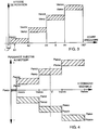
- the program defines, as a function of the inertia of the rotating body, minimum and maximum values of rotation speed for ranges of angular deviations.
- the program then forces the asynchronous motor to rotate between the minimum and maximum speeds thus determined as a function of the inertia and of the instantaneous angular difference by acting on the supply of energy delivered by the supply card 10 (FIG. 1).
- the program works as follows: for a given angular deviation A, one must be in the hatched areas. Consequently, if the speed of rotation is greater, for example for an instantaneous angular difference A of between A 3 and A 4 at the maximum speed Vmax3, the motor 1 is braked by injecting it with a "negative" power tending to make the motor turn. in the opposite direction until you are in the hatched area. Conversely, if this speed is lower than the minimum speed Vmin3, the additional electrical power is injected to increase this speed of rotation until it is in the hatched area.
- the maximum and minimum speeds decrease, which contributes to the slowing down of the moving equipment.
- the minimum speed is low or close to zero and the maximum speed is limited to a threshold Vmax1.
- the electromagnetic brake 2 or any other equivalent brake brakes the motor 1 in a measured manner to slow it down notably.
- the moving equipment 6, 7, 8 and 9 then continues on its way and reaches the vicinity of zero in a range I of tolerated uncertainty.
- the brake 2 acts definitively to stop and block the motor 1, the pulleys 3 and 5 and the moving assembly 6, 7, 8 and 9 in rotation until the balancing weight has been placed by the operator and the operator has preferably restarted the machine manually.
- the invention is particularly advantageous in that it allows the use of a single-phase asynchronous electric motor of known type and in common use in balancing devices, in particular vehicle wheel balancers and in that the fuzzy logic used to control the device makes it possible to very quickly and safely obtain the stopping of the rotating body in the desired predetermined radial positions.
- the program After placing the balancing weight and restarting the wheel manually, the program performs a similar cycle for the second laying plane and the second predetermined radial direction using the same method as that described with reference to FIG. 3.
- FIG. 4 shows a diagram representing the programming mode of the power injected into the motor as a function of the value of the instantaneous speed of the motor supplied by the optical encoder or other equivalent angular encoder.
- the instantaneous speed V of the motor is between the speeds Vmax2 and Vmax3
- the power injected into the motor will be authorized in an area between a minimum power Pmin3 and a maximum power Pmax3.
- We will designate by positive power a power injected into the motor which tends to make the motor turn in the real direction of rotation at this instant and by negative power a power electric injected into the motor which tends to make the motor turn in the opposite direction from its real direction of rotation at this instant, that is to say to carry out an electric braking of the motor.
- the power control is easily carried out by detecting the instant of zero crossing of the phase of the sector and by triggering the conduction of the triacs at a determined instant relative to this instant of crossing by zero of the phase of the sector to obtain the powers. electric positive or negative desired.
- the principle of operation and triggering of the conduction of triacs to produce a positive electrical power or a negative electrical power is well known and does not require a detailed description. It should only be specified that the maximum power Pmax1 for a very low speed is much less than the blocking power of the brake associated with the electric motor and is not likely to significantly heat the windings of the single-phase asynchronous electric motor used from preferably in the present invention.
- the engine is immobilized before cutting its electrical supply.
- the electrically actuated brake mounted on the motor shaft can be integrated into the motor (commercially available brake motor) or be independent of the motor.
- the brake can be mounted on any location of the motion transmission and can be pneumatic, hydraulic or consisting of an electromagnet triggering a disc brake.
Landscapes
- Physics & Mathematics (AREA)
- General Physics & Mathematics (AREA)
- Connection Of Motors, Electrical Generators, Mechanical Devices, And The Like (AREA)
- Testing Of Balance (AREA)
- Braking Arrangements (AREA)
Applications Claiming Priority (2)
| Application Number | Priority Date | Filing Date | Title |
|---|---|---|---|
| FR9511652 | 1995-10-04 | ||
| FR9511652A FR2739689B1 (fr) | 1995-10-04 | 1995-10-04 | Procede et dispositif d'equilibrage d'un corps tournant en rotation par addition de masses d'equilibrage |
Publications (2)
| Publication Number | Publication Date |
|---|---|
| EP0767367A1 true EP0767367A1 (de) | 1997-04-09 |
| EP0767367B1 EP0767367B1 (de) | 2002-05-02 |
Family
ID=9483219
Family Applications (1)
| Application Number | Title | Priority Date | Filing Date |
|---|---|---|---|
| EP96402065A Revoked EP0767367B1 (de) | 1995-10-04 | 1996-09-27 | Verfahren und Vorrichtung zum Auswuchten eines rotierenden Körpers durch Anbringen von Ausgleichsgewichten |
Country Status (4)
| Country | Link |
|---|---|
| US (1) | US5889206A (de) |
| EP (1) | EP0767367B1 (de) |
| DE (1) | DE69620968D1 (de) |
| FR (1) | FR2739689B1 (de) |
Cited By (2)
| Publication number | Priority date | Publication date | Assignee | Title |
|---|---|---|---|---|
| CN111623983A (zh) * | 2020-05-12 | 2020-09-04 | 清华大学 | 一种滚动轴承换能装置及其应用 |
| CN113945322A (zh) * | 2020-07-16 | 2022-01-18 | 香港城市大学深圳研究院 | 叶轮动平衡自动调整设备及方法 |
Families Citing this family (4)
| Publication number | Priority date | Publication date | Assignee | Title |
|---|---|---|---|---|
| DE20308066U1 (de) * | 2003-05-21 | 2003-07-24 | att Automotive Testing Technologies GmbH, 77694 Kehl | Vorrichtung zum Auswuchten eines Fahrzeugrades |
| DE102004017767B4 (de) * | 2004-04-13 | 2013-09-19 | Snap-On Equipment Gmbh | Verfahren und Vorrichtung zum Auswuchten eines Fahrzeugrades |
| FR2886012B1 (fr) * | 2005-05-23 | 2007-07-06 | Snecma Moteurs Sa | Procede de calibrage en masse de pieces destinees a etre montees en peripherie d'un rotor |
| NL2021103B1 (en) * | 2018-06-12 | 2019-12-17 | Atlas Technologies Holding Bv | A method for balancing a wheel with integrated electric motor |
Citations (2)
| Publication number | Priority date | Publication date | Assignee | Title |
|---|---|---|---|---|
| JPS58132641A (ja) * | 1982-02-02 | 1983-08-08 | Kokusai Keisokki Kk | 自動不釣合点位置決め方式 |
| EP0383038A2 (de) * | 1989-02-13 | 1990-08-22 | Nagahama Seisakusho Ltd. | Steuerungsvorrichtung zum Indizieren des Rotors einer Unwuchtmessmaschine |
Family Cites Families (9)
| Publication number | Priority date | Publication date | Assignee | Title |
|---|---|---|---|---|
| US4085619A (en) * | 1976-02-09 | 1978-04-25 | Royal Industries, Inc. | Electronic balancer for vehicle wheels |
| US4046017A (en) * | 1976-12-16 | 1977-09-06 | Fmc Corporation | Wheel balancing apparatus |
| US4285240A (en) * | 1980-01-11 | 1981-08-25 | Fmc Corporation | Wheel unbalance measurement system and method |
| US4341119A (en) * | 1980-03-18 | 1982-07-27 | Nortron Corporation | Data input system for dynamic balancing machine |
| DE3316945A1 (de) * | 1983-05-09 | 1984-11-15 | Gebr. Hofmann GmbH & Co KG, Maschinenfabrik, 6102 Pfungstadt | Vorrichtung zum automatischen einsetzen von ausgleichsgewichten an kraftfahrzeugraedern beim auswuchten derselben |
| US5209116A (en) * | 1989-03-10 | 1993-05-11 | Denshi Seiki Kogyo Kabushiki Kaisha | Unbalance point positioning apparatus and method |
| DE4006867A1 (de) * | 1990-03-05 | 1991-09-12 | Reutlinger & Soehne Gmbh U Co | Vorrichtung zum eindrehen eines wuchtkoerpers in eine bearbeitungsposition |
| ES2101899T3 (es) * | 1993-06-07 | 1997-07-16 | Schenck Rotec Gmbh | Procedimiento para la eliminacion de valores de medida no relevantes de una señal de medida del desequilibrio. |
| US5661672A (en) * | 1993-06-07 | 1997-08-26 | Schenck Rotec Gmbh | Process for mask irrelevant measured values in an unbalance measuring signal |
-
1995
- 1995-10-04 FR FR9511652A patent/FR2739689B1/fr not_active Expired - Fee Related
-
1996
- 1996-09-27 DE DE69620968T patent/DE69620968D1/de not_active Expired - Lifetime
- 1996-09-27 EP EP96402065A patent/EP0767367B1/de not_active Revoked
- 1996-10-01 US US08/720,810 patent/US5889206A/en not_active Expired - Fee Related
Patent Citations (2)
| Publication number | Priority date | Publication date | Assignee | Title |
|---|---|---|---|---|
| JPS58132641A (ja) * | 1982-02-02 | 1983-08-08 | Kokusai Keisokki Kk | 自動不釣合点位置決め方式 |
| EP0383038A2 (de) * | 1989-02-13 | 1990-08-22 | Nagahama Seisakusho Ltd. | Steuerungsvorrichtung zum Indizieren des Rotors einer Unwuchtmessmaschine |
Non-Patent Citations (1)
| Title |
|---|
| PATENT ABSTRACTS OF JAPAN vol. 7, no. 249 (P - 234)<1394> 5 November 1983 (1983-11-05) * |
Cited By (4)
| Publication number | Priority date | Publication date | Assignee | Title |
|---|---|---|---|---|
| CN111623983A (zh) * | 2020-05-12 | 2020-09-04 | 清华大学 | 一种滚动轴承换能装置及其应用 |
| CN111623983B (zh) * | 2020-05-12 | 2021-06-04 | 清华大学 | 一种滚动轴承换能装置及其应用 |
| CN113945322A (zh) * | 2020-07-16 | 2022-01-18 | 香港城市大学深圳研究院 | 叶轮动平衡自动调整设备及方法 |
| CN113945322B (zh) * | 2020-07-16 | 2024-01-26 | 香港城市大学深圳研究院 | 叶轮动平衡自动调整设备及方法 |
Also Published As
| Publication number | Publication date |
|---|---|
| EP0767367B1 (de) | 2002-05-02 |
| DE69620968D1 (de) | 2002-06-06 |
| FR2739689A1 (fr) | 1997-04-11 |
| FR2739689B1 (fr) | 1997-11-28 |
| US5889206A (en) | 1999-03-30 |
Similar Documents
| Publication | Publication Date | Title |
|---|---|---|
| EP2003461B1 (de) | Verfahren zum Feststellen eines Ausfalls einer oder mehrerer Phasen bei einem Dauermagnet-Synchronmotor | |
| FR2720460A1 (fr) | Procédé pour déterminer la température de la surface de frein pour une roue de véhicule automobile. | |
| FR2780921A1 (fr) | Dispositif de sortie motrice et son procede de controle et vehicule hybride actionne par le dispositif de sortie motrice | |
| FR2818315A1 (fr) | Procede et dispositif de commande pour determiner l'angle vilebrequin d'un moteur a combustion interne, et train d'entrainement | |
| FR2791749A1 (fr) | Procede et dispositif pour determiner le point d'attaque d'un embrayage assiste | |
| EP0767367B1 (de) | Verfahren und Vorrichtung zum Auswuchten eines rotierenden Körpers durch Anbringen von Ausgleichsgewichten | |
| FR2575225A1 (fr) | Procede de commande en boucle fermee de la vitesse au ralenti d'un moteur a combustion interne | |
| EP2232048B1 (de) | Ansteuerverfahren eines selbstgeführten starter-generators mit einem abgekürzten vormagnetisierungsschritt | |
| EP1136696B1 (de) | Vorrichtung und Verfahren zur Posionierung einer Brennkraftmaschine in einer startgünstigen Position | |
| FR2815087A1 (fr) | Dispositif pour demarrer un moteur a combustion interne | |
| FR2530173A1 (fr) | Procede et montage pour freiner une partie de machine et pour l'arreter | |
| EP0091336B1 (de) | Waschmaschine mit Vorrichtung zum Erfassen der Unwuchtschwingungen | |
| FR2697332A3 (fr) | Procédé destiné à déterminer le balourd d'un tambour d'une machine à laver chargée. | |
| FR2850220A1 (fr) | Dispositif de commande et procede de commande pour un moteur electrique | |
| FR3060499A1 (fr) | Procede de gestion d'une phase transitoire du demarrage d'un moteur thermique par une machine electrique | |
| EP3318747A1 (de) | Anlassverfahren eines wärmekraftmotors einer motorantriebsanlage eines fahrzeugs, insbesondere eines kraftfahrzeugs | |
| EP0468862B1 (de) | Regelverfahren für die Rotationsgeschwindigkeit der Trommel einer Zentrifugiermaschine als Funktion der Unwucht und Maschine zur Verwendung dieses Verfahrens | |
| FR2566204A1 (fr) | Dispositif de regulation de la vitesse d'un moteur electrique asynchrone | |
| FR2886221A1 (fr) | Procede de transmission de puissance d'un vehicule hybride entre un arbre d'un moteur thermique et un arbre de roues d'un vehicule | |
| EP3361087A1 (de) | System und verfahren zur repositionierung des rotors eines verbrennungsmotors | |
| FR2576469A1 (fr) | Dispositif de commande d'un moteur pas-a-pas | |
| FR2690651A3 (fr) | Procédé et dispositif pour commander le compresseur d'une installation de climatisation dans un véhicule automobile. | |
| EP0736964B1 (de) | Basisantriebssystem für einen Schrittmotor mit verbesserter Rücksetzschaltung | |
| FR2791828A1 (fr) | Dispositif de commande de demarreur de vehicule automobile produisant une usure faible du demarreur | |
| FR3166504A1 (fr) | Procédé et dispositif de contrôle d’un moteur électrique à courant continu sans balais, notamment un moteur d’entrainement d’un générateur d’un flux d’air |
Legal Events
| Date | Code | Title | Description |
|---|---|---|---|
| PUAI | Public reference made under article 153(3) epc to a published international application that has entered the european phase |
Free format text: ORIGINAL CODE: 0009012 |
|
| AK | Designated contracting states |
Kind code of ref document: A1 Designated state(s): DE ES GB IT |
|
| 17P | Request for examination filed |
Effective date: 19971004 |
|
| 17Q | First examination report despatched |
Effective date: 20000121 |
|
| GRAG | Despatch of communication of intention to grant |
Free format text: ORIGINAL CODE: EPIDOS AGRA |
|
| REG | Reference to a national code |
Ref country code: GB Ref legal event code: IF02 |
|
| GRAG | Despatch of communication of intention to grant |
Free format text: ORIGINAL CODE: EPIDOS AGRA |
|
| GRAH | Despatch of communication of intention to grant a patent |
Free format text: ORIGINAL CODE: EPIDOS IGRA |
|
| GRAH | Despatch of communication of intention to grant a patent |
Free format text: ORIGINAL CODE: EPIDOS IGRA |
|
| GRAA | (expected) grant |
Free format text: ORIGINAL CODE: 0009210 |
|
| AK | Designated contracting states |
Kind code of ref document: B1 Designated state(s): DE ES GB IT |
|
| PG25 | Lapsed in a contracting state [announced via postgrant information from national office to epo] |
Ref country code: IT Free format text: LAPSE BECAUSE OF FAILURE TO SUBMIT A TRANSLATION OF THE DESCRIPTION OR TO PAY THE FEE WITHIN THE PRE;WARNING: LAPSES OF ITALIAN PATENTS WITH EFFECTIVE DATE BEFORE 2007 MAY HAVE OCCURRED AT ANY TIME BEFORE 2007. THE CORRECT EFFECTIVE DATE MAY BE DIFFERENT FROM THE ONE RECORDED.SCRIBED TIME-LIMIT Effective date: 20020502 Ref country code: GB Free format text: LAPSE BECAUSE OF FAILURE TO SUBMIT A TRANSLATION OF THE DESCRIPTION OR TO PAY THE FEE WITHIN THE PRESCRIBED TIME-LIMIT Effective date: 20020502 |
|
| REG | Reference to a national code |
Ref country code: GB Ref legal event code: FG4D Free format text: NOT ENGLISH |
|
| REF | Corresponds to: |
Ref document number: 69620968 Country of ref document: DE Date of ref document: 20020606 |
|
| PG25 | Lapsed in a contracting state [announced via postgrant information from national office to epo] |
Ref country code: DE Free format text: LAPSE BECAUSE OF FAILURE TO SUBMIT A TRANSLATION OF THE DESCRIPTION OR TO PAY THE FEE WITHIN THE PRESCRIBED TIME-LIMIT Effective date: 20020803 |
|
| GBV | Gb: ep patent (uk) treated as always having been void in accordance with gb section 77(7)/1977 [no translation filed] |
Effective date: 20020502 |
|
| PG25 | Lapsed in a contracting state [announced via postgrant information from national office to epo] |
Ref country code: ES Free format text: LAPSE BECAUSE OF FAILURE TO SUBMIT A TRANSLATION OF THE DESCRIPTION OR TO PAY THE FEE WITHIN THE PRESCRIBED TIME-LIMIT Effective date: 20021128 |
|
| PLBQ | Unpublished change to opponent data |
Free format text: ORIGINAL CODE: EPIDOS OPPO |
|
| PLBI | Opposition filed |
Free format text: ORIGINAL CODE: 0009260 |
|
| PLBF | Reply of patent proprietor to notice(s) of opposition |
Free format text: ORIGINAL CODE: EPIDOS OBSO |
|
| 26 | Opposition filed |
Opponent name: SNAP-ON EQUIPMENT GMBH Effective date: 20030203 |
|
| PLBB | Reply of patent proprietor to notice(s) of opposition received |
Free format text: ORIGINAL CODE: EPIDOSNOBS3 |
|
| RDAF | Communication despatched that patent is revoked |
Free format text: ORIGINAL CODE: EPIDOSNREV1 |
|
| RDAG | Patent revoked |
Free format text: ORIGINAL CODE: 0009271 |
|
| STAA | Information on the status of an ep patent application or granted ep patent |
Free format text: STATUS: PATENT REVOKED |
|
| 27W | Patent revoked |
Effective date: 20040706 |