EP0767413A2 - Machine à copier ayant des dispositif de transport de documents disposés l'un derrière l'autre - Google Patents
Machine à copier ayant des dispositif de transport de documents disposés l'un derrière l'autre Download PDFInfo
- Publication number
- EP0767413A2 EP0767413A2 EP96306656A EP96306656A EP0767413A2 EP 0767413 A2 EP0767413 A2 EP 0767413A2 EP 96306656 A EP96306656 A EP 96306656A EP 96306656 A EP96306656 A EP 96306656A EP 0767413 A2 EP0767413 A2 EP 0767413A2
- Authority
- EP
- European Patent Office
- Prior art keywords
- radf
- tray
- document
- job
- platen
- Prior art date
- Legal status (The legal status is an assumption and is not a legal conclusion. Google has not performed a legal analysis and makes no representation as to the accuracy of the status listed.)
- Withdrawn
Links
Images


Classifications
-
- G—PHYSICS
- G03—PHOTOGRAPHY; CINEMATOGRAPHY; ANALOGOUS TECHNIQUES USING WAVES OTHER THAN OPTICAL WAVES; ELECTROGRAPHY; HOLOGRAPHY
- G03G—ELECTROGRAPHY; ELECTROPHOTOGRAPHY; MAGNETOGRAPHY
- G03G15/00—Apparatus for electrographic processes using a charge pattern
- G03G15/60—Apparatus which relate to the handling of originals
-
- G—PHYSICS
- G03—PHOTOGRAPHY; CINEMATOGRAPHY; ANALOGOUS TECHNIQUES USING WAVES OTHER THAN OPTICAL WAVES; ELECTROGRAPHY; HOLOGRAPHY
- G03G—ELECTROGRAPHY; ELECTROPHOTOGRAPHY; MAGNETOGRAPHY
- G03G2215/00—Apparatus for electrophotographic processes
- G03G2215/00172—Apparatus for electrophotographic processes relative to the original handling
- G03G2215/00354—Specific document handling machines
- G03G2215/00358—Plural feed trays for document sets, e.g. multi-job
Definitions
- This invention relates to electrostatographic reproduction machines, and more particularly to a reproduction machine having a tandem automatic document handler.
- the process of electrostatographic reproduction includes charging a photoconductive member to a substantially uniform potential so as to sensitize the surface thereof. A charged portion of the photoconductive surface is exposed at an exposure station to a light image of an original document being reproduced.
- hard copy jobs each consisting of a set of sheets of original documents are held and automatically handled by a recirculating document handler to the exposure station.
- Document handlers used with electrostatographic reproduction machines frequently are provided with a recirculating mode whereby stacked documents are withdrawn individually and sequentially from an input holding tray, passed to the exposure station, and then are outputted back to the holding tray for subsequent recirculation in the previous manner. Some document handlers also invert the documents so that a duplex document may be imaged on both sides.
- Exposing a document sheet fed for example by a document handler to the exposure station records an electrostatic latent image onto the photoconductive member. After the electrostatic latent image is recorded as such, the latent image is subsequently developed using a development apparatus by bringing a charged dry or liquid developer material into contact with the latent image.
- a development apparatus by bringing a charged dry or liquid developer material into contact with the latent image.
- Two component and single component developer materials are commonly used.
- a typical two-component dry developer material has magnetic carrier granules with fusible toner particles adhering triobelectrically thereto.
- a single component dry developer material typically comprising toner particles only can also be used.
- the toner image formed by such development is subsequently transferred to a copy sheet, on which it is then heated and permanently fused in order to form a hardcopy of the original image.
- Electrostatographic reproduction machines based on this process are now commonly used in business environments, and frequently in a common or central location where a user or users are often required to sequentially reproduce several multiple-sheet hard copy jobs, one after another. Such sequentially produced jobs currently can be pre-programmed or programmed ahead and batched.
- Pre-programming of such jobs for reproduction on a reproduction machine at a common or central location is frequently an inconvenient process. This is because users ordinarily have to remove the first hard copy job from a single or sequential job document handler in order to load and run a second such job, pre-programmed or not. It is often the case that a second person (user or operator) wanting to make copies on a conventional machine, upon seeing a first person at the machine, must either wait or go away and return later when they hope the machine would be idle. Even in the case of a single person desiring to reproduce several such jobs, the person ordinarily must wait for the first job to be completed in order to be able to program, load and run a second job.
- an automatic document feeder including a reserved feeding station for automatically feeding a plurality of stacks of originals.
- the ADF includes a reversible first conveyor for conveying documents without inversion to a processing station.
- the reserved feeding station includes an inverting mechanism for inverting originals being returned to the reserved feeding station.
- an automatic original document feeder includes a first sheet path for inverting and guiding an original from a stacker, a second sheet path branching from the first sheet path in a switchback fashion for guiding the sheet to a process position, and a third sheet path branching from the first sheet path in a switchback fashion for discharging the sheet from the process position after inversion.
- an electrostatographic reproduction machine including a Tandem Automatic Document Handler (TADH) for programmed ahead handling of first and second hard copy jobs in tandem.
- the TADH includes a housing for mounting over a platen of the reproduction machine.
- the TADH also includes a first Recirculating Automatic Document Feeder (RADF) assembly mounted within the housing.
- the first RADF assembly has a first RADF tray and a first document path for recirculatingly moving sheets of documents seriatim from the first RADF tray over the platen, and back into the first RADF tray.
- the TADH includes a second Recirculating Automatic Document Feeder (RADF) assembly mounted within the housing and in alignment with the first RADF assembly.
- the second RADF assembly includes a second RADF tray and a second document path for recirculatingly feeding sheets of documents seriatim from the second RADF tray over the platen, and back into the second RADF tray.
- TADH Tandem Automatic Document Handling
- the TADH method includes loading multiple document sheets of the first job in a first Recirculating Automatic Document Feeder (RADF) assembly that includes a first RADF tray, and recirculatingly moving the documents sheets of the first job seriatim from the first RADF tray along a first document path through a point for location over a platen of the machine, back into the first RADF tray.
- RDF Recirculating Automatic Document Feeder
- the TADH method also includes loading multiple document sheets of the second job in a second Recirculating Automatic Document Feeder (RADF) assembly that includes a second RADF tray, and recirculatingly feeding sheets of documents of the second job seriatim, after recirculatingly moving the documents sheets of the first job, from the second RADF tray along a first portion of a second document path through a point for location over a platen of the machine, and then along a second portion of the second document path located below the first RADF tray, back into the second RADF tray.
- RADF Recirculating Automatic Document Feeder
- the machine 8 has conventional imaging processing stations associated therewith, including a charging station AA, an imaging/exposing station BB, a development station CC, a transfer station DD, a fusing station EE, and a cleaning station FF. It will be understood that a conventional finishing station (not shown) could easily be included in the machine.
- the machine 8 has a photoconductive belt 10 with a photoconductive layer 12 which is supported by a drive roller 14 and a tension roller 15.
- the drive roller 14 functions to drive the belt in the direction indicated by arrow 18.
- the drive roller 14 is itself driven by a motor (not shown) by suitable means, such as a belt drive.
- the photoconductive belt 10 is charged at the charging station AA by a corona generating device 20.
- the charged portion of the belt is then transported by action of the drive roller 14 to the imaging/exposing station BB where a latent image is formed on the belt 10 corresponding to the image on a document positioned on a platen 24 via the light lens imaging system 28 of the imaging/exposing station BB.
- the light lens imaging system can easily be changed to an input/output scanning terminal or an output scanning terminal driven by a data input signal to likewise image the belt 10.
- the portion of the belt 10 bearing the latent image is then transported to the development station CC where the latent image is developed by electrically charged toner material from a magnetic developer roller 30 of the developer station CC.
- the developed image on the belt is then transported to the transfer station DD where the toner image is transferred to a copy sheet substrate fed by a copy handling system 31.
- a corona generating device 32 is provided for charging the copy sheet substrate so as to attract the charged toner image from the photoconductive belt 10 to the copy sheet substrate.
- the copy sheet substrate with the transferred image thereon is then directed to the fuser station EE.
- the fuser apparatus at station EE includes a heated fuser roll 34 and backup pressure roll 36.
- the heated fuser roll 34 and pressure roll 36 rotatably cooperate to fuse and fix the toner image onto the copy sheet substrate.
- the copy sheet substrate then, as is well known, may be selectively transported to an output tray 38 or to a duplex tray 40 along a selectable duplex path 42 for duplexing.
- the portion of the belt 10 from which the developed image was transferred is then advanced to the cleaning station FF where residual toner and charge on the belt are removed by a cleaning device such as a blade 44, and a discharge lamp (not shown).
- the imaging cycle can then be repeated.
- the machine 8 includes a frame 58 and a Tandem Automatic Document Handler (TADH) 60 according to the present invention.
- the TADH includes a housing 62 for mounting over the platen 24 of the reproduction machine 8.
- the TADH 60 also includes a first Recirculating Automatic Document Feeder (RADF) assembly 64 that is mounted within the housing 62.
- the first RADF assembly 64 includes a first RADF tray 66, and a first document path 68 for recirculatingly moving sheets of documents seriatim from the first RADF tray 66 onto the platen 24, and back into the first RADF tray 66.
- the TADH further includes a second Recirculating Automatic Document Feeder (RADF) assembly 70 mounted within the housing 62 and in alignment with the first RADF assembly 64.
- the second RADF assembly 70 includes a second RADF tray 72 and a second document path 74 for recirculatingly feeding sheets of documents seriatim from the second RADF tray 72 onto the platen 24, and back into the second RADF tray 72.
- RDF Recirculating Automatic Document Feeder
- the first document path 68, and the second document path 74 merge at a point P2 where a document sheet being moved along either path can be located for exposure over the platen 24.
- a catch tray 76 is provided and is mounted relative to one end of the housing 62 in alignment with the first and the second document paths 68, 74 respectively, for receiving document sheets fed from over the platen 24 along either of the first and the second document paths 68, 74.
- the Tandem Automatic Document Handler 60 includes a platen cover member 80, and the second document path 74 includes feed portion 82 for feeding sheets to point P2 over the platen, and a return portion 84 for returning document sheets from the point P2 over the platen into the second RADF tray 72.
- a good part of the return portion 84 is conveniently located above the document cover member 80, but below the first RADF tray 66 so as to allow uninterrupted and independent recirculated sheet movement from the point P2 into the second RADF tray 72.
- the machine 8 includes a programmable electronic control subsystem or ESS 100 for controlling the functioning of the components and subassemblies of the machine 8 and TADH 60.
- controller 100 which is preferably a conventional microprocessor system. It is contemplated that the controller controls all machine steps and functions described herein, as well as that of any and/or all apparatus and devices associated with the document handler.
- first RADF tray 66 of the first Recirculating Automatic Document Feeder (RADF) assembly 64 To operate the TADH 60 multiple document sheets of a first job 110 are loaded (side-being-imaged-up) in the first RADF tray 66 of the first Recirculating Automatic Document Feeder (RADF) assembly 64.
- the document sheets of the first job 110 are recirculatingly moved seriatim, from the first RADF tray 66 along the first document path 68.
- Each sheet being moved as such is inverted, moved through the point P2 over a platen 24 where it can be exposed for imaging, and then back into the first RADF tray 66.
- the sheets are fed from the tray 66 for example by a bottom feeder vacuum belt device 112, past a first gating member 114 for pick up and positioning under the platen cover member 80.
- the platen cover member can include a belt 116 for receiving and moving a sheet fed from the first RADF tray 66 into an exposure position over the platen 24. From the position P2 over the platen where the document sheet is exposed or imaged, it is then moved past a second gating member 122, and a third gating member 124, for reinverted return into the tray 66 where the side being imaged is again up.
- This imaging move from and back to the first tray 66 can therefore be repeated as often as is desired in accordance to preprogrammed instructions for the particular first job.
- a second job 120 can be loaded (side-being-imaged-up) in the second RADF tray 72 of the second Recirculating Automatic Document Feeder (RADF) assembly 70.
- Sheets of documents of the second job 120 are then fed recirculatingly seriatim, (after recirculatingly moving the document sheets of the first job 110), from the second RADF tray 72 along a first portion 82 of the second document path 74.
- Each sheet being moved as such is inverted, moved along the path portion 82 through the point P2 over a platen 24 where it is exposed and imaged, and then back along the second portion 84 of the path 74, into the second RADF tray 72.
- the sheets are fed from the tray 72 for example by a bottom feeder vacuum belt device 126, inverted and moved along the first portion 82 for pick up by, and positioning under, the platen cover member 80 for imaging. From the position P2 over the platen 24, where the document sheet is exposed or imaged, it is then moved past the second gating member 122 (set to block sheet movement along path 68). The sheet is there reinverted and moved along the second portion 84 of path 74 past a reset first gating member 114, for return into the second tray 72 where the side being imaged is again up.
- This imaging move from and back to the second tray 72 similarly can therefore be repeated as often as is desired in accordance to preprogrammed instructions for the particular second job.
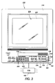
- the U.I 130 may include a color touch monitor having hard and soft control buttons.
- the U.I. 130 as such will include a CRT 216 of the type having a peripheral frame 218 and a video screen 220.
- Soft buttons in the form of icons or pictograms are displayable and usable on the screen 220. Messages can be displayed within a window 224.
- Hard control buttons 222 are provided, as well as a keypad 230 for programming copy quantities.
- Other control buttons for example include a job interrupt button 236.
- the ESS 100 includes a first programming channel for pre-programming first jobs 110 to be run using the first RADF assembly 64, and a second programming channel for pre-programming second jobs 120 to be run using the second RADF assembly 70.
- the electronic control subsystem 100 includes means and capability for accepting job programming of an idle one of either channel regardless of whether the other channel is also idle or not idle. Accordingly, the second channel can be preprogrammed while a job is being run at any stage through the first RADF assembly 64. The same is true of preprogramming the first channel while the second channel is busy running a second job through the second RADF assembly 70.
- each channel has preferably three states, "OFF”, “PROGRAMMED”, and "RUNNING".
- each channel includes a channel selection button 138, 140 respectively.
- Each channel selection button may include as illustrated a first activatable colored (yellow) LED 142 and a second activatable colored (green) LED 144, where the yellow indicates the "programmed” state, the green the “running” state, and both LEDs off, indicating the "off" state of the respective channels.
- a single operator with a first job 110 and a second job 120 can preprogram both the first and second channels to reproduce two physically and numerically different jobs by selecting one and then the other of the two channels.
- the operator can then load the first job in the first RADF assembly 64, and the second job in the second RADF assembly 70.
- Activation of either start button 134, 136 will cause the one job to be run automatically (in a manner to be described below), after which (or unless interrupted) the other job as programmed is also run automatically (also to be described below).
- job 1 (first job 110) can be loaded into the first RADF tray 66, and run recirculatingly through the first path 68 of the first RADF assembly 60 as many times as are required by a number of desired copies, and returned to the first RADF tray 66.
- job2 (job2)
- job 120 can be loaded into the second RADF tray 72, and run recirculatingly through the second path 74 of the second RADF assembly 70 as many times as are required by a number of desired copies, and returned to the second RADF tray 72.
- the first job 110 can be run after the second job 120 and vice versa.
- the first job 110 can be run through the first RADF assembly as above, and the originals instead of being returned to the first RADF tray 66, can be outputted instead to the catch tray 76, thereby freeing the first tray 66 and first RADF 64 for a third job to be programmed as a new first job even while the second RADF tray 72 is tied up with job 2 as shown.
- the second job 120 (job 2) instead, after being run as above through the second RADF assembly 70, can be outputted to the catch tray 76, thereby freeing the second RADF tray 72 and assembly 70 for such third job.
- the programmable controller 100 thus can be programmed to automatically run the first job 110 and output the first set of document sheets thereof back into the first RADF tray 66, or into the side catch tray 76, and to then automatically run, after running the first job 110, the second job 120 and return the second set of document sheets thereof into the second holding tray 72 of the second RADF assembly, or into the catch tray 76.
- the steps of programming of the controller and the loading of multiple document sheets of the second job 120 into the second RADF tray 72 can occur while, or contemporaneously with, the recirculating movement of the documents sheets of the first job 110 through the first RADF assembly 64.
- the programming of the controller and the loading of multiple document sheets of the first job 110 into the first RADF tray 66 can occur while, or contemporaneously with recirculating movement of the documents sheets of the second job 120 through the second RADF assembly 72.
- a second operator or user who walks up to the machine 8 while it is running a first job through the first RADF assembly does not have to wait or walk away to come back later.
- Such an operator or user simply can use the channel selection button ---to select the second channel, program a job to run through the second RADF assembly 70, load the programmed job into the second RADF tray 72, and then walk away.
- the programmed job will automatically run as above once the first job has been completed.
- an advantageous feature of the present invention includes an ability with the first and second RADF assemblies 64, 70 respectively, to use the job interrupt button 236 to interrupt a job running in one of the RADF assemblies (either first or second), and to then use the appropriate start button 134, 136 to recirculatingly run a multiple copies job through the other RADF assembly.
- a second job 120 requiring a large number of copies can be run in a first imaging pass from the second tray 72, and then along the first path 68 from the platen position P2 into an empty first tray 66.
- the job 120 can thereafter be recirculatingly run from tray 66 through the first path 68 as many times as are necessary until the job is completed.
- the originals of this job can, of course, be outputted either back into the first tray 66, or even back into the second tray 72 via the second portion 84 of the second path 74. These originals can also be outputted to the catch tray 76 if it is empty by the time the job is completed. This approach may be necessary and advantageous because relative to the platen position P2, the first document path 68 is shorter than the second path 74.
- the machine includes a reproducing unit for reproducing images from each document sheet of a set of hard copy document sheets in a hard copy reproduction job.
- the reproducing unit includes a hard copy document sheet exposure station.
- the machine also includes a tandem automatic document handler (TADH) that comprises a first recirculating automatic document sheet feeder (RADF) assembly connected to the reproducing unit for holding and automatically feeding each document sheet of a set of document sheets to the exposure station.
- the first RADF assembly includes a first holding tray for holding a first hard copy job, and a first recirculating document path.
- the tandem automatic document handler also comprises a second automatic document feeder (RADF) assembly connected to the reproducing unit in alignment with the first RADF assembly for holding and automatically feeding each document sheet of a set of document sheets to the exposure station.
- the second RADF assembly includes a second document path, and a second holding tray for holding a second hard copy job.
- a side catch tray is mounted to the machine relative to the exposure station for receiving and holding a set of document sheets fed from the exposure station.
- the machine further includes a programmable controller programmed (i) to automatically run the first job and output the first set of document sheets thereof into the first RADF tray or into the side catch tray, and (ii) to automatically run, after running the first job, the second job and return the second set of document sheets thereof into the second holding tray of the second RADF assembly, or output them to the catch tray, or even into the first RADF tray depending on which is empty.
- a programmable controller programmed (i) to automatically run the first job and output the first set of document sheets thereof into the first RADF tray or into the side catch tray, and (ii) to automatically run, after running the first job, the second job and return the second set of document sheets thereof into the second holding tray of the second RADF assembly, or output them to the catch tray, or even into the first RADF tray depending on which is empty.
Landscapes
- Physics & Mathematics (AREA)
- General Physics & Mathematics (AREA)
- Exposure Or Original Feeding In Electrophotography (AREA)
- Control Or Security For Electrophotography (AREA)
- Conveyance By Endless Belt Conveyors (AREA)
Applications Claiming Priority (2)
| Application Number | Priority Date | Filing Date | Title |
|---|---|---|---|
| US538658 | 1995-10-03 | ||
| US08/538,658 US5669057A (en) | 1995-10-03 | 1995-10-03 | Reproduction machine having a tandem automatic document handler |
Publications (2)
| Publication Number | Publication Date |
|---|---|
| EP0767413A2 true EP0767413A2 (fr) | 1997-04-09 |
| EP0767413A3 EP0767413A3 (fr) | 1997-05-02 |
Family
ID=24147865
Family Applications (1)
| Application Number | Title | Priority Date | Filing Date |
|---|---|---|---|
| EP96306656A Withdrawn EP0767413A3 (fr) | 1995-10-03 | 1996-09-13 | Machine à copier ayant des dispositif de transport de documents disposés l'un derrière l'autre |
Country Status (5)
| Country | Link |
|---|---|
| US (1) | US5669057A (fr) |
| EP (1) | EP0767413A3 (fr) |
| JP (1) | JPH09146310A (fr) |
| BR (1) | BR9603985A (fr) |
| MX (1) | MX9603860A (fr) |
Cited By (1)
| Publication number | Priority date | Publication date | Assignee | Title |
|---|---|---|---|---|
| DE19840382C2 (de) * | 1998-09-04 | 2001-12-06 | Agfa Gevaert Ag | Verfahren und Vorrichtung zum digitalen Aufbelichten von Bildern auf lichtempfindliches Material |
Families Citing this family (4)
| Publication number | Priority date | Publication date | Assignee | Title |
|---|---|---|---|---|
| JPH10161359A (ja) * | 1996-11-29 | 1998-06-19 | Mita Ind Co Ltd | 予約型原稿搬送装置 |
| US6902987B1 (en) * | 2000-02-16 | 2005-06-07 | Ziptronix, Inc. | Method for low temperature bonding and bonded structure |
| DE102011006456B4 (de) * | 2011-03-30 | 2012-11-22 | Inotec Gmbh | Vorrichtung und Verfahren zum Einscannen von Dokumenten |
| US8585037B1 (en) | 2012-11-08 | 2013-11-19 | Xerox Corporation | Tandem media tray using mid-tray sensor |
Family Cites Families (14)
| Publication number | Priority date | Publication date | Assignee | Title |
|---|---|---|---|---|
| US4099150A (en) * | 1976-06-01 | 1978-07-04 | Eastman Kodak Company | Apparatus for producing duplex collated copies |
| US4126390A (en) * | 1977-05-02 | 1978-11-21 | Eastman Kodak Company | Job stream programmer apparatus |
| US4248529A (en) * | 1979-04-13 | 1981-02-03 | Canon Kabushiki Kaisha | Automatic image original handling device |
| US4273439A (en) * | 1979-07-09 | 1981-06-16 | International Business Machines Corporation | Document feeder system having a suspending/commencing mode with a judgment decision capability |
| US4508447A (en) * | 1983-04-21 | 1985-04-02 | Xerox Corporation | Alternative feeding document recirculation |
| JPS61272761A (ja) * | 1985-05-27 | 1986-12-03 | Minolta Camera Co Ltd | 複写装置 |
| JPH0662258B2 (ja) * | 1985-09-13 | 1994-08-17 | キヤノン株式会社 | 原稿送り装置 |
| JPS62222939A (ja) * | 1986-03-24 | 1987-09-30 | Canon Inc | 原稿自動送り装置 |
| US4834360A (en) * | 1987-12-17 | 1989-05-30 | Xerox Corporation | Job batching system for high capacity copier with RDH |
| US5040019A (en) * | 1987-12-18 | 1991-08-13 | Minolta Camera Kabushiki Kaisha | Copying apparatus having automatic document feeder & sorter |
| US5081699A (en) * | 1988-10-03 | 1992-01-14 | Xerox Corporation | Program ahead file transfer in a reproduction machine |
| NL8901828A (nl) * | 1989-07-14 | 1991-02-01 | Oce Nederland Bv | Inrichting voor het aan- en afvoeren van originelen bij een kopieerapparaat. |
| US5192976A (en) * | 1989-11-05 | 1993-03-09 | Canon Kabushiki Kaisha | Sheet original feeding apparatus with detachable auxiliary feeder |
| JPH0459563A (ja) * | 1990-06-27 | 1992-02-26 | Toshiba Corp | 画像形成装置 |
-
1995
- 1995-10-03 US US08/538,658 patent/US5669057A/en not_active Expired - Fee Related
-
1996
- 1996-09-04 MX MX9603860A patent/MX9603860A/es not_active IP Right Cessation
- 1996-09-13 EP EP96306656A patent/EP0767413A3/fr not_active Withdrawn
- 1996-09-25 JP JP8252553A patent/JPH09146310A/ja not_active Abandoned
- 1996-10-02 BR BR9603985A patent/BR9603985A/pt not_active IP Right Cessation
Cited By (1)
| Publication number | Priority date | Publication date | Assignee | Title |
|---|---|---|---|---|
| DE19840382C2 (de) * | 1998-09-04 | 2001-12-06 | Agfa Gevaert Ag | Verfahren und Vorrichtung zum digitalen Aufbelichten von Bildern auf lichtempfindliches Material |
Also Published As
| Publication number | Publication date |
|---|---|
| JPH09146310A (ja) | 1997-06-06 |
| US5669057A (en) | 1997-09-16 |
| EP0767413A3 (fr) | 1997-05-02 |
| BR9603985A (pt) | 1998-06-09 |
| MX9603860A (es) | 1997-04-30 |
Similar Documents
| Publication | Publication Date | Title |
|---|---|---|
| US3830590A (en) | Sorter apparatus of printer system | |
| US4657376A (en) | Image forming apparatus in which an image forming unit and a document feeding unit are alternately operated | |
| US5036361A (en) | Job requirements calculation and display | |
| US5218406A (en) | Memory card features | |
| EP0261975A2 (fr) | Dispositifs d'alimentation de documents | |
| US3871643A (en) | Sorter control | |
| US4511243A (en) | Time to completion interaction for a copier | |
| US3845949A (en) | Sorter control to prevent over-stacking in the sorter trays | |
| US4835572A (en) | Image forming apparatus enabling reversible selection of a default mode of operation | |
| JPS63172172A (ja) | 複写機 | |
| EP0457552B1 (fr) | Machine de reprographie | |
| US5669057A (en) | Reproduction machine having a tandem automatic document handler | |
| US4685797A (en) | Copying machine control system | |
| JPS6243180B2 (fr) | ||
| US4627710A (en) | Customized job default set-up | |
| US5136343A (en) | High-volume duplicator having efficient operation in the uncollated duplex mode | |
| US5155538A (en) | Automatic mode change to enhance document copier efficiency | |
| JPS6214660A (ja) | タブ付き複写用紙を扱える複写機 | |
| JP2000053263A (ja) | 用紙処理装置 | |
| JPH02132021A (ja) | 用紙カセットの給紙方向切換装置 | |
| JP2654471B2 (ja) | 電子写真複写装置 | |
| JPS6313060A (ja) | 記録装置 | |
| JPH02235076A (ja) | 画像処理装置 | |
| US5599010A (en) | Automatic loading/unloading of a document feeder for a reproduction apparatus | |
| JPH03119370A (ja) | ページ自動選択複写機 |
Legal Events
| Date | Code | Title | Description |
|---|---|---|---|
| PUAI | Public reference made under article 153(3) epc to a published international application that has entered the european phase |
Free format text: ORIGINAL CODE: 0009012 |
|
| PUAL | Search report despatched |
Free format text: ORIGINAL CODE: 0009013 |
|
| AK | Designated contracting states |
Kind code of ref document: A2 Designated state(s): DE FR GB |
|
| AK | Designated contracting states |
Kind code of ref document: A3 Designated state(s): DE FR GB |
|
| 17P | Request for examination filed |
Effective date: 19971103 |
|
| 17Q | First examination report despatched |
Effective date: 19971201 |
|
| STAA | Information on the status of an ep patent application or granted ep patent |
Free format text: STATUS: THE APPLICATION IS DEEMED TO BE WITHDRAWN |
|
| 18D | Application deemed to be withdrawn |
Effective date: 20060331 |