EP0767451A1 - Méthode de détection du bord de bande - Google Patents
Méthode de détection du bord de bande Download PDFInfo
- Publication number
- EP0767451A1 EP0767451A1 EP96307099A EP96307099A EP0767451A1 EP 0767451 A1 EP0767451 A1 EP 0767451A1 EP 96307099 A EP96307099 A EP 96307099A EP 96307099 A EP96307099 A EP 96307099A EP 0767451 A1 EP0767451 A1 EP 0767451A1
- Authority
- EP
- European Patent Office
- Prior art keywords
- head assembly
- signal
- tape
- width
- edge
- Prior art date
- Legal status (The legal status is an assumption and is not a legal conclusion. Google has not performed a legal analysis and makes no representation as to the accuracy of the status listed.)
- Withdrawn
Links
- 238000000034 method Methods 0.000 title claims abstract description 33
- 238000010586 diagram Methods 0.000 description 5
- 230000004907 flux Effects 0.000 description 3
- 230000007704 transition Effects 0.000 description 3
- 230000001010 compromised effect Effects 0.000 description 1
- 238000001514 detection method Methods 0.000 description 1
- 238000011084 recovery Methods 0.000 description 1
Images

Classifications
-
- G—PHYSICS
- G11—INFORMATION STORAGE
- G11B—INFORMATION STORAGE BASED ON RELATIVE MOVEMENT BETWEEN RECORD CARRIER AND TRANSDUCER
- G11B5/00—Recording by magnetisation or demagnetisation of a record carrier; Reproducing by magnetic means; Record carriers therefor
- G11B5/48—Disposition or mounting of heads or head supports relative to record carriers ; arrangements of heads, e.g. for scanning the record carrier to increase the relative speed
- G11B5/54—Disposition or mounting of heads or head supports relative to record carriers ; arrangements of heads, e.g. for scanning the record carrier to increase the relative speed with provision for moving the head into or out of its operative position or across tracks
- G11B5/55—Track change, selection or acquisition by displacement of the head
- G11B5/5504—Track change, selection or acquisition by displacement of the head across tape tracks
- G11B5/5508—Control circuits therefor
Definitions
- the present invention relates generally to a track following positioning method, and more particularly to a method for controlling the position of a magnetic head relative to a magnetic media, such as a magnetic tape.
- Digital data is conventionally stored on magnetic media such as magnetic tape or diskette in the form of flux transitions on the surface of the media.
- Data recovery consists of determining the presence, and relative timing, of such flux transitions.
- Optimal operation of a recording device therefore depends upon the proper orientation and position of the magnetic head. Otherwise, the use of an improperly oriented and positioned recording head may result in the information being recorded in a manner that cannot be accurately retrieved on playback. Similarly, an improperly oriented or positioned playback head may result in the inaccurate retrieval of information even if the information was properly recorded. In either case, the integrity of the information storage system may be compromised and information may be lost.
- Prior art methods for properly orienting and positioning a magnetic head include detecting the edge of a magnetic tape. Conventionally, such as for eight millimeter tapes, the location of a particular track from the bottom edge of a magnetic tape is standard. Therefore, properly locating the edge of tape is critical for accurately positioning a magnetic tape head. Precisely determining the edge of tape provides a reference position for the tape head to locate other track locations.
- the prior art methods which utilize detecting the edge of tape suffer from numerous drawbacks, however, including but not limited to inaccurate positioning of the tape head due to the use of analog detectors, number of circuits involved, etc.
- the present invention provides a method for digitally detecting a top or bottom edge of a magnetic media, such as magnetic tape, to enable accurate positioning of a transversely movable magnetic head assembly at any of a plurality of track locations across a width of magnetic media.
- the magnetic head assembly is positioned to a location that is known to be on the tape.
- the magnetic head assembly typically includes one or more read and write heads. A reference signal is recorded, and the width is measured by stepping the head assembly down through the recorded signal and testing for the presence or absence of the signal.
- the read/write head assembly is successively stepped down the center of the magnetic tape (with a write pass followed by a read pass) until it fails to recover a signal, thus indicating that the write head has gone off the edge of the tape.
- the read/write head assembly is then stepped back up on the tape until a signal is recovered with a width that is equal to one-half (1/2) the reference width.
- a digital burst detector is utilized to determined the presence or non presence of a specific signal.
- the present invention provides a method for digitally detecting a top or bottom edge of a magnetic media, such as magnetic tape, to enable accurate positioning of a transversely movable magnetic head assembly at any of a plurality of track locations across a width of magnetic media.
- a diagram of a read/write head assembly 10 contacting a typical physical track layout of magnetic media, such as magnetic tape 12 is illustrated.
- the location of a particular track from the bottom edge 14 of the tape 12 is standard. Therefore, properly locating the edge 14 of tape 12 is critical for accurately positioning a magnetic tape head assembly 10.
- the present invention precisely determines the edge 14 of tape 12, therefore providing a reference position for the tape head assembly 10 to locate other track locations.
- both the top edge 16 and bottom edge 14 of tape 12 may be determined.
- the present invention will be described utilizing detection of the bottom edge 14 of tape 12.
- the present invention is not limited, however, to locating the bottom edge 14 of tape 12.
- the tracks are referenced to the center of the tape 12. Therefore, the present invention may be used to determine the top edge 16 and bottom edge 14 of tape 12.
- the magnetic head assembly 10 is positioned to a location that is known to be on the tape 12.
- the magnetic head assembly 10 typically includes one or more read heads 18 and write heads 20.
- a reference signal is recorded, and the width is measured by stepping the head assembly 10 down through the recorded signal and testing for the presence or absence of the signal.
- the read/write head assembly 10 is successively stepped down the center of the magnetic tape 12 (with a write pass followed by a read pass) until it fails to recover a signal, thus indicating that the write head 20 has gone off the edge 14 of the tape 12.
- the read/write head assembly 10 is then stepped back up on the tape 12 until a signal is recovered with a width that is equal to one-half (1/2) the reference width.
- a digital burst detector is utilized to determined the presence or non presence of a specific signal.
- a tape head assembly 10 including a read head 18 and write head 20 detects the information stored on the magnetic media as it moves by the read head 18 at a predetermined speed.
- Digital data is conventionally stored on magnetic media in the form of flux transitions on the surface of the media.
- the magnetic media may be a magnetic tape 12, diskette or other magnetic media.
- a typical physical track layout of magnetic tape 12 includes data tracks written in parallel in the forward and reverse directions.
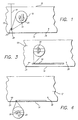
- FIG. 1 is a diagram of a read/write head assembly 10 surface contacting a typical physical track layout of magnetic tape 12.
- the read/write head assembly 10 is transversely movable across the width of the multitrack tape 12 as shown by the arrow 22.
- the read/write head assembly 10 may be moved by a conventional bi-directional stepper motor (not shown) coupled to the head assembly 10 by a lead screw (not shown) or other conventional means.
- the tape head assembly 10 moves in either a first or second transverse direction, typically orthogonal, to the motion of the magnetic tape 12.
- the tape head assembly 10 include one or more read and write heads, all having their centers substantially in alignment parallel to the direction of tape motion. As is shown in FIG. 1, the tape head assembly 10 includes a read head 18 and write head 20. The width of the write head 20 is approximately three times the width of the read head 18, which is approximately symmetrically centered about the write head 20.
- the tape 12 includes a top 16 and bottom edge 14 of tape 12.
- a plurality of beginning of tape (BOT) holes 24 are longitudinally located adjacent the physical beginning of tape 12. More particularly, as shown in FIG. 1, a pattern of double holes 24 indicative of the BOT are disposed at the beginning of tape 12. Located a predetermined distance from the BOT holes 24 are a single hole 26 indicative of the load point (LP), i.e., the point at which normal recording operations may begin.
- a conventionally formatted magnetic tape 12 also includes a series of end of tape (EOT) holes (not shown) longitudinally located adjacent the physical end of tape, as well as other tape markers (not shown).
- the read/write head assembly 10 is initially positioned to a predetermined location 28 such that the head assembly 10 is completely within the tape 12.
- an initial known or reference burst signal 30 is written utilizing the write head 20, preferably in the load zone area i.e. the region between the BOT 24 and the LP holes 26.
- the initial reference burst signal 30 may be an alternating current signal of fixed frequency and predetermined amplitude used for positioning of the head assembly 10 on the magnetic tape 12. The signal is also used to control the gain of a read amplifier in the tape transport system.
- the width of the initial reference burst signal 30 is then measured (reference width) by stepping the read/write head assembly 10 along the width of the tape 12 down one step at a time towards the bottom edge 14 of tape 12 as shown in FIG. 3. After the reference width of the initial reference burst signal 30 has been determined, the initial reference burst signal 30 is erased and the next sequence of operations pertaining to determining the approximate edge 14 of tape 12 begins.
- the edge 14 of tape 12 is subsequently determined utilizing the width of the initial reference burst signal 30.
- the read head 18 is stepped towards the bottom edge 14 of tape 12 one initial reference burst signal width and another reference burst signal is written.
- the tape 12 is then rewound and read to determine whether the previously written reference burst signal is present. Therefore, rather than checking the width of the reference burst signal, the tape 12 is checked to determine whether the reference burst signal is present.
- the read head 18 is stepped down towards the edge 14 of tape 12 one initial reference burst width and another reference burst signal is written and read as described above. This step is continuously repeated until no reference burst signal is detected.
- the signal is erased and the read head 18 is stepped back one initial reference burst signal width.
- the read head 18 is stepped one initial reference burst width in the opposite direction, away from the bottom edge 14 of tape 12.
- a reference burst signal is then repeatedly written and measured until the width of the measured reference burst signal is one-half the initial reference burst width, thus indicating that at the time the signal was recorded, the write head 20 was half on and half off the edge 14 of tape 12 as shown in FIG. 4. Since the read head 18 is symmetrically centered on the write head 20, the edge 14 of tape 12 is detected.
- FIG. 2 is a flow chart of an algorithm 40 for digitally detecting the edge 14 of the tape to enable accurate positioning of the read/write head assembly 10 across the width of the magnetic tape 12.
- the read/write head assembly 10 in step 1, is positioned to a predetermined location 28 on the magnetic tape 12 such that the read head 18 and write head 20 are completely within the tape 12.
- an initial known or reference burst signal 30 is written by the write head 20.
- step 3 While stepping the head assembly 10 one step at a time (step 3), the width of the initial reference burst signal 30 is measured and recorded (step 4). In step 3, the head assembly 10 is stepped a predetermined increment, which is determined in accordance with numerous factors, including the dimensions of the head assembly 10, tape 12, etc. The initial reference burst signal 30 is then erased (step 5).
- Steps 6-9 are directed to searching for an approximate edge 14 of tape 12 utilizing the width of the initial reference burst signal determined in step 4.
- the present invention may be used for locating the top 16 or bottom edge 14 of tape 12.
- the present algorithm 40 will be described in the context of locating a bottom edge 14 of tape 12.
- step 6 the read head 18 is stepped towards the bottom edge 14 of tape 12 one initial reference burst signal width.
- a known signal is then written (step 7).
- the tape 12 is rewound to the initial position in step 7 before the known signal was written and then read in step 8.
- steps 5-9 are repeated.
- step 9 When no known signal is detected (step 9), the signal is erased (step 10) and the read head 18 is stepped back one initial reference burst signal width (step 11), away from the bottom edge 14 of tape 12. A known signal is then written in step 12. The tape 12 is then rewound once again (step 13) and the width of the signal is measured (step 14). Referring to FIG. 4, in step 15, if the width of the measured signal equals one-half the initial reference burst signal width measured in step 4, the edge 14 of tape 12 is detected. If the width does not equal one-half the initial reference burst signal width, steps 10-15 are repeated until the width of the measured signal equals one-half the initial reference burst signal width (step 15).
- a digital burst detector is preferably utilized to determined the presence or non presence of the known or reference burst signal.
- the read/write head assembly 10 is initially positioned to a predetermined location 28 such that the head assembly 10 is completely within the tape 12.
- an initial known or reference burst signal 30 is written utilizing the write head 20, preferably in the region between the BOT 24 and the LP holes 26.
- the width of the initial reference burst signal 30 is then measured by stepping the read/write head assembly 10 along the width of the tape 12 up one step at a time towards the top edge 16 of tape 12. After the width of the initial, reference burst signal 30 has been determined, the initial reference burst signal 30 is erased and the next sequence of operations pertaining to determining the approximate top edge 16 of tape 12 begin.
- the top edge 16 of tape 12 is subsequently determined utilizing the width of the initial reference burst signal 30.
- the read head 18 is stepped towards the top edge 16 of tape 12 one initial reference burst signal width and another reference burst signal is written.
- the tape 12 is then rewound and read to determine whether the previously written reference burst signal is present.
- the read head 18 is stepped up towards the top edge 16 of tape 12 one initial reference burst width and another reference burst signal is written and read as described above. This step is continuously repeated until no reference burst signal is detected.
- the signal is erased and the read head 18 is stepped back down initial reference burst signal width.
- the read head 18 is stepped one initial reference burst width in the opposite direction, away from the top edge 16 of tape 12.
- a reference burst signal is then repeatedly written and measured until the width of the measured reference burst signal is one-half the initial reference burst width, thus indicating that at the time the signal was recorded, the write head 20 was half on and half off the top edge 16 of tape 12. Since the read head 18 is symmetrically centered on the write head 20, the top edge 16 of tape 12 is detected.
Landscapes
- Adjustment Of The Magnetic Head Position Track Following On Tapes (AREA)
Applications Claiming Priority (4)
| Application Number | Priority Date | Filing Date | Title |
|---|---|---|---|
| US636743 | 1990-12-31 | ||
| US472795P | 1995-10-02 | 1995-10-02 | |
| US4727 | 1995-10-02 | ||
| US63674396A | 1996-04-19 | 1996-04-19 |
Publications (1)
| Publication Number | Publication Date |
|---|---|
| EP0767451A1 true EP0767451A1 (fr) | 1997-04-09 |
Family
ID=26673380
Family Applications (1)
| Application Number | Title | Priority Date | Filing Date |
|---|---|---|---|
| EP96307099A Withdrawn EP0767451A1 (fr) | 1995-10-02 | 1996-09-27 | Méthode de détection du bord de bande |
Country Status (2)
| Country | Link |
|---|---|
| EP (1) | EP0767451A1 (fr) |
| JP (1) | JPH09171612A (fr) |
Cited By (1)
| Publication number | Priority date | Publication date | Assignee | Title |
|---|---|---|---|---|
| US9640209B1 (en) | 2016-09-20 | 2017-05-02 | International Business Machines Corporation | Generating defect signals in time based servo tape storage systems |
Citations (6)
| Publication number | Priority date | Publication date | Assignee | Title |
|---|---|---|---|---|
| EP0270275A1 (fr) * | 1986-12-05 | 1988-06-08 | Minnesota Mining And Manufacturing Company | Procédé et appareil pour localiser le bord d'une bande magnétique |
| US4802030A (en) * | 1986-06-25 | 1989-01-31 | Hewlett-Packard Company | Head-tape alignment apparatus with a tape edge find operation |
| US4977468A (en) * | 1986-10-09 | 1990-12-11 | Kabushiki Kaisha Sankyo Seiki Seisakusho | Tape edge detecting method and device therefor |
| JPH0460913A (ja) * | 1990-06-26 | 1992-02-26 | Sankyo Seiki Mfg Co Ltd | テープエッジ検出方法 |
| US5111347A (en) * | 1988-10-11 | 1992-05-05 | K.K. Sankyo Seiki Seisakusho | Method of detecting tape edge |
| EP0563452A2 (fr) * | 1992-03-31 | 1993-10-06 | Tandberg Data A/S | Méthode et dispositif de détection de bord de bande |
-
1996
- 1996-09-27 EP EP96307099A patent/EP0767451A1/fr not_active Withdrawn
- 1996-09-30 JP JP25958896A patent/JPH09171612A/ja active Pending
Patent Citations (6)
| Publication number | Priority date | Publication date | Assignee | Title |
|---|---|---|---|---|
| US4802030A (en) * | 1986-06-25 | 1989-01-31 | Hewlett-Packard Company | Head-tape alignment apparatus with a tape edge find operation |
| US4977468A (en) * | 1986-10-09 | 1990-12-11 | Kabushiki Kaisha Sankyo Seiki Seisakusho | Tape edge detecting method and device therefor |
| EP0270275A1 (fr) * | 1986-12-05 | 1988-06-08 | Minnesota Mining And Manufacturing Company | Procédé et appareil pour localiser le bord d'une bande magnétique |
| US5111347A (en) * | 1988-10-11 | 1992-05-05 | K.K. Sankyo Seiki Seisakusho | Method of detecting tape edge |
| JPH0460913A (ja) * | 1990-06-26 | 1992-02-26 | Sankyo Seiki Mfg Co Ltd | テープエッジ検出方法 |
| EP0563452A2 (fr) * | 1992-03-31 | 1993-10-06 | Tandberg Data A/S | Méthode et dispositif de détection de bord de bande |
Non-Patent Citations (1)
| Title |
|---|
| PATENT ABSTRACTS OF JAPAN vol. 16, no. 256 (P - 1368) 10 June 1992 (1992-06-10) * |
Cited By (2)
| Publication number | Priority date | Publication date | Assignee | Title |
|---|---|---|---|---|
| US9640209B1 (en) | 2016-09-20 | 2017-05-02 | International Business Machines Corporation | Generating defect signals in time based servo tape storage systems |
| US9741380B1 (en) | 2016-09-20 | 2017-08-22 | International Business Machines Corporation | Generating defect signals in time based servo tape storage systems |
Also Published As
| Publication number | Publication date |
|---|---|
| JPH09171612A (ja) | 1997-06-30 |
Similar Documents
| Publication | Publication Date | Title |
|---|---|---|
| JP4266423B2 (ja) | 位置情報を確定する方法及び線形データ記憶テープ及びテープヘッドの位置決定方法 | |
| US5396376A (en) | Multi-track embedded servo recording format and method | |
| CA1139436A (fr) | Dispositif de positionnement et formattage pour support a bande magnetique | |
| US4996609A (en) | Magnetic head recording multitrack servo patterns | |
| US4422111A (en) | High capacity data cartridge system and preformatted cartridge for use therein | |
| US7206170B2 (en) | Thin film servo head apparatus with canted servo gaps | |
| US4845577A (en) | Apparatus and method for enabling rapid searching of helically recorded magnetic tape | |
| US5291348A (en) | High density servo tracking | |
| US4492993A (en) | Magnetic recording tape and corresponding method providing indication of end-of-tape conditions | |
| US5285331A (en) | System for aligning a read head gap over a track of magnetic data | |
| US4786984A (en) | Method and apparatus for locating the edge of a magnetic tape | |
| US6798608B2 (en) | Active detection and acquisition of a servo track subject to lateral motion | |
| US4796125A (en) | Optimizing the positioning of a pair of magnetic heads relative to spaced tracks on magnetic tape | |
| EP0767451A1 (fr) | Méthode de détection du bord de bande | |
| US6437930B1 (en) | Method of estimating the clearance between a read/write transducer head and a magnetic recording medium | |
| JPH07101491B2 (ja) | 磁気テープの縁検知方法 | |
| US5726824A (en) | Head positioning in a multi-track magnetic tape recorder/player | |
| US5323276A (en) | Error removal method for a multi-track tape recorder system | |
| EP0767452A1 (fr) | Méthode pour chercher le centre d'un rafale de référence | |
| US5111347A (en) | Method of detecting tape edge | |
| US6906881B2 (en) | Apparatus and method to erase a magnetic tape | |
| JPH0439126B2 (fr) | ||
| US6317283B1 (en) | Methods and apparatus for calibration of a rotating scanner to a track recorded on a tape | |
| US6665137B2 (en) | Method for locating data tracks on a tape media | |
| CA1056498A (fr) | Methode et dispositif d'enregistrement de donnees sur bande magnetique |
Legal Events
| Date | Code | Title | Description |
|---|---|---|---|
| PUAI | Public reference made under article 153(3) epc to a published international application that has entered the european phase |
Free format text: ORIGINAL CODE: 0009012 |
|
| AK | Designated contracting states |
Kind code of ref document: A1 Designated state(s): DE FR GB IT NL |
|
| 17P | Request for examination filed |
Effective date: 19971008 |
|
| STAA | Information on the status of an ep patent application or granted ep patent |
Free format text: STATUS: THE APPLICATION IS DEEMED TO BE WITHDRAWN |
|
| 18D | Application deemed to be withdrawn |
Effective date: 20000401 |