EP0767699B1 - Dämpfung von brecherströmung in einem mehrphasigen flüssigkeitsstrom - Google Patents
Dämpfung von brecherströmung in einem mehrphasigen flüssigkeitsstrom Download PDFInfo
- Publication number
- EP0767699B1 EP0767699B1 EP95924951A EP95924951A EP0767699B1 EP 0767699 B1 EP0767699 B1 EP 0767699B1 EP 95924951 A EP95924951 A EP 95924951A EP 95924951 A EP95924951 A EP 95924951A EP 0767699 B1 EP0767699 B1 EP 0767699B1
- Authority
- EP
- European Patent Office
- Prior art keywords
- liquid
- flow rate
- separator
- gas
- outlet
- Prior art date
- Legal status (The legal status is an assumption and is not a legal conclusion. Google has not performed a legal analysis and makes no representation as to the accuracy of the status listed.)
- Expired - Lifetime
Links
- 239000012530 fluid Substances 0.000 title claims abstract description 42
- 230000001629 suppression Effects 0.000 title description 2
- 239000007788 liquid Substances 0.000 claims abstract description 170
- 238000000034 method Methods 0.000 claims abstract description 26
- 241000237858 Gastropoda Species 0.000 claims abstract description 13
- 238000005259 measurement Methods 0.000 claims description 5
- 239000000203 mixture Substances 0.000 description 8
- 230000004907 flux Effects 0.000 description 7
- 238000009491 slugging Methods 0.000 description 6
- 230000010355 oscillation Effects 0.000 description 5
- 238000011144 upstream manufacturing Methods 0.000 description 5
- 238000004519 manufacturing process Methods 0.000 description 4
- XLYOFNOQVPJJNP-UHFFFAOYSA-N water Substances O XLYOFNOQVPJJNP-UHFFFAOYSA-N 0.000 description 4
- 230000007246 mechanism Effects 0.000 description 3
- 239000003921 oil Substances 0.000 description 3
- 230000001105 regulatory effect Effects 0.000 description 3
- 230000001276 controlling effect Effects 0.000 description 2
- 239000010779 crude oil Substances 0.000 description 2
- 238000002474 experimental method Methods 0.000 description 2
- 238000012545 processing Methods 0.000 description 2
- LYCAIKOWRPUZTN-UHFFFAOYSA-N Ethylene glycol Chemical compound OCCO LYCAIKOWRPUZTN-UHFFFAOYSA-N 0.000 description 1
- 230000000903 blocking effect Effects 0.000 description 1
- 238000004891 communication Methods 0.000 description 1
- 238000010586 diagram Methods 0.000 description 1
- 235000003642 hunger Nutrition 0.000 description 1
- 239000003595 mist Substances 0.000 description 1
- 230000037351 starvation Effects 0.000 description 1
- -1 stratified flow Substances 0.000 description 1
- 238000012546 transfer Methods 0.000 description 1
Images


Classifications
-
- B—PERFORMING OPERATIONS; TRANSPORTING
- B01—PHYSICAL OR CHEMICAL PROCESSES OR APPARATUS IN GENERAL
- B01D—SEPARATION
- B01D19/00—Degasification of liquids
- B01D19/0063—Regulation, control including valves and floats
-
- E—FIXED CONSTRUCTIONS
- E21—EARTH OR ROCK DRILLING; MINING
- E21B—EARTH OR ROCK DRILLING; OBTAINING OIL, GAS, WATER, SOLUBLE OR MELTABLE MATERIALS OR A SLURRY OF MINERALS FROM WELLS
- E21B43/00—Methods or apparatus for obtaining oil, gas, water, soluble or meltable materials or a slurry of minerals from wells
- E21B43/34—Arrangements for separating materials produced by the well
-
- E—FIXED CONSTRUCTIONS
- E21—EARTH OR ROCK DRILLING; MINING
- E21B—EARTH OR ROCK DRILLING; OBTAINING OIL, GAS, WATER, SOLUBLE OR MELTABLE MATERIALS OR A SLURRY OF MINERALS FROM WELLS
- E21B2200/00—Special features related to earth drilling for obtaining oil, gas or water
- E21B2200/09—Detecting, eliminating, preventing liquid slugs in production pipes
Definitions
- the invention relates to suppression of slug flow in a multi-phase fluid stream. More particularly, the invention relates to a method and system for preventing growth of liquid slugs in a stream of multiphase fluid flowing through a flowline system including a riser section and a gas/liquid separator located downstream the riser section.
- a method for preventing slug growth in a pipeline system during simultaneous transportation of a gas and a liquid through the pipeline system is disclosed in Oil & Gas journal, Nov. 12, 1979.
- a valve is arranged at the top of a riser, which valve is manually or automatically regulated so as to minimise the pipeline pressure upstream of the riser and to minimise the differential pressure fluctuations in the riser.
- Transmitters are used to transmit pressure signals for regulating the valve, which transmitters are installed at a subsea part of the pipeline system.
- This known method is based on the assumptions that severe slugging only occurs in pipelines having a section of downward inclination when seen in the direction of flow and that slug growth can be prevented by regulating the volumetric fluid flux as a function of fluid pressure variations.
- JP-A-63-274408 discloses a separator control apparatus which adjusts a valve in a gas outlet of a gas liquid separator by adding the outputs of a supersonic multiphase flowmeter in the inlet of the separator and of a manometer within the separator to exert a constant pressure in the separator.
- EP-B-410522 discloses a method of preventing slug growth in a stream of multiphase fluid flowing from a flowline into a gas/liquid separator, whereby fluid flow rate control means are provided to manipulate the fluid flow rate.
- This known method comprises measuring the liquid flow rate in the liquid outlet of the separator and the gas flow rate in the gas outlet thereof, determining the fluid flux defined as the sum of the liquid flow rate and the gas flow rate, and operating the fluid flow rate control means so as to reduce a variation of the fluid flux.
- a drawback of this known method and of the method disclosed in JP-A-63-274408 is that measurement of the sum of the liquid and gas flow rates in a multiphase fluid stream is difficult and requires complex measuring equipment.
- An object of the invention is to provide an improved method and system for preventing growth of liquid slugs in a flowline system.
- the invention aims to provide a method of preventing growth of liquid slugs in a stream of multiphase fluid flowing from a flowline into a gas/liquid separator that has a liquid outlet provided with liquid flow rate control means and a gas outlet provided with gas flow rate control means.
- the method according to the invention comprises the steps of:
- the liquid level in the separator By controlling the liquid level in the separator to be as constant as possible, and by controlling the control variable to be as constant as possible, improved control over the flow regime in the flowline system is achieved so that growth of liquid slugs can be prevented in an improved manner. Furthermore, it was found that instead of selecting the fluid flux (being the sum of the liquid flow rate and the gas flow rate) as the controlled variable, the liquid flow rate, the gas flow rate, or the fluid pressure can be selected as the controlled variable.
- the fluid flux being the sum of the liquid flow rate and the gas flow rate
- the present invention aims to provide a system for preventing growth of liquid slugs in a stream of multiphase fluid flowing from a flowline into a gas/liquid separator, said gas/liquid separator having a liquid outlet provided with liquid flow rate control means and a gas outlet provided with gas flow rate control means.
- the system according to the invention comprises:
- the second mechanism may support the first mechanism, but it was found to occur also when a low point in the pipeline system is absent.
- the flowline forms the downstream end part of a subsea pipeline system leading to an offshore platform, said end part suitably being a riser debouching into the gas/liquid separator.
- Control of the liquid level in the separator is effectively achieved if said liquid control means is operated so as to reduce the difference between said liquid level and the selected reference value of the liquid level, and said gas flow rate control means is operated so as to reduce the difference between said control variable and the reference value of the control variable.
- control variable is preferably selected to be the fluid pressure at or near the separator.
- control variable is suitably selected to be the liquid flow rate in the liquid outlet of the separator.
- Severe slug flow can be effectively suppressed if said control variable is selected to be the liquid flow rate in the liquid outlet of the separator, either continuously or after the start-up period.
- control variable can suitably be selected to be the sum of the liquid flow rate in the liquid outlet and the gas flow rate in the gas outlet, either continuously or after the start-up period.
- the reference value of the control variable when said variable is the liquid flow rate or the sum of the liquid flow rate and the gas flow rate, can be generated by reducing a difference between the fluid pressure at or near the separator and a selected reference value of the fluid pressure.
- the gas/liquid separator indicated hereinbefore can have sufficient capacity for processing the fluid stream, in which case said separator can be the only separator in the system.
- the separator can form a mini-separator which is located upstream a slug catching separator. The mini-separator then forms a primary separator of which the gas outlet and the liquid outlet debouche into the slug catching separator which forms a secondary separator.
- the flowline system of Fig. 1 comprises a pipeline 1 extending on the seafloor 3 from a wellhead (not shown) to an offshore platform 5, an upwardly inclined pipeline section in the form of a riser 7 connected to the platform 5 and a gas/liquid separator 9 having a liquid outlet conduit 13 and a gas outlet conduit 14.
- the liquid outlet conduit 13 is provided with a liquid flow control valve 15, and the gas outlet conduit is provided with a gas flow control valve 16.
- the valves 15, 16 can be of any suitable type such as a vortex amplifier disclosed in The Oilman, August 1987, pp. 82-85.
- a gas flow meter 17 is provided in the gas outlet conduit 14 and a liquid flow meter 19 is provided in the liquid outlet conduit 13.
- the separator 9 is further provided with a liquid level gauge 25 and a pressure gauge 27.
- a control system 30 is provided which receives signals from the gas flow meter 17, the liquid flow meter 19, the liquid level gauge 25, and the pressure gauge 27, which control system 30 controls the valves 15, 16 in a manner depending on the signals received by the control system 30.
- the liquid outlet conduit 13 and the gas outlet conduit 14 are in fluid communication with the interior of a slug-catching separator (not shown) located downstream the separator 9.
- the slug-catching separator is of a size considerably larger than the separator 9.
- Fig. 2 shows schematically the control system 30 of Fig. 1 in more detail, whereby corresponding reference numerals refer to corresponding components.
- the arrows shown in Fig. 2 indicate the direction of transfer of electric control signals from one component to another.
- the control system 30 includes a liquid level controller 32 which manipulates valve 15 in response to input signals received from liquid level gauge 25 via control line 34 and from a liquid level set-point 36 via control line 38.
- a pressure controller 40 is connectable to valve 16 via switch 42 and control line 44 so as to manipulate valve 16 in response to input signals received from pressure gauge 27 via control line 46 and from a pressure set-point 48 via control line 49.
- a liquid flow rate controller 50 is connectable to valve 16 via switch 42 and control line 44 so as to manipulate valve 16 in response to input signals received from liquid flow meter 19 via control line 52 and a liquid flow rate set-point 54 via control line 55.
- a mixture controller 56 is connectable to valve 16 via switch 42 and control line 44 so as to manipulate valve 16 in response to input signals received from gas flow meter 17 via control line 58, from liquid flow meter 19 via control line 60, and from a pressure controller 62 via control line 64.
- the signals in control lines 58, 60 are summed so as to provide a fluid flux signal which is transferred to mixture controller via control line 59.
- the pressure controller 62 receives input signals from pressure gauge 27 via control line 65 and from pressure set-point 66 via control line 67.
- a mixture of gas and liquid flows from the wellhead through the underwater pipeline 1 and riser 7 into the gas/liquid separator 9.
- Gas is discharged from the separator 9 through the gas outlet conduit 14 and liquid through the liquid outlet conduit 13.
- the volumetric gas flux in the gas outlet conduit 14 is continuously measured using the gas volumetric flow meter 17 and the volumetric liquid flux in the liquid outlet conduit 13 is continuously measured using the liquid volumetric flow meter 19.
- the liquid level in the separator 9 is continuously measured using the liquid level gauge 25 and the pressure in the separator 9 is continuously measured using the pressure gauge 27.
- valve 16 When control of fluid-flow using controller 30 is started, for example when control is switched from manual to automatic just after blockage of the riser 7 due to the occurrence of a slug has occurred, the switch 42 is switched to the position in which pressure controller 40 is connected to valve 16.
- the pressure controller 40 manipulates valve 16 in a manner so as to decrease a difference between a pressure signal from pressure gauge 27 and a signal from set-point 48.
- Control valve 15 is manipulated by level controller 32 so as to decrease a difference between a signal from liquid level gauge 25 and a signal from set-point 36.
- the switch 42 When the liquid slug starts to flow into the separator, the switch 42 is switched to the position in which liquid flow rate controller 50 is connected to valve 16.
- the liquid flow rate controller 50 manipulates valve 16 in a manner so as to decrease a difference between a liquid flow rate signal from flow meter 19 and a signal from set-point 54. Thereafter switch 42 is switched to the position in which mixture controller 56 is connected to valve 16, which mixture controller 56 manipulates valve 16 in a manner so as to decrease a difference between a fluid flow rate signal, defined as the sum of a liquid flow rate signal from liquid flow meter 19 and a gas flow rate signal from gas flow meter 17, and a signal received from pressure controller 62.
- Pressure controller 62 provides an input signal to mixture controller 56 via control line 64, which input signal is aimed at reducing a difference between a pressure signal from pressure gauge 27 and a signal from set-point 66.
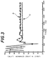
- Fig. 3 indicating the liquid contents of the slug catching separator as a function of time, using a constant drawn down rate of the slug catching separator.
- the control variable was selected to be the liquid flow rate (line a) and the fluid flow rate (line b), the latter being the sum of the liquid flow rate and the gas flow rate.
- the control variable was the liquid flow rate (line a)
- mixture controller 56 was used whereby the control line 58 was disconnected so that the fluid flow rate signal in control line 59 was identical to the liquid flow rate signal in control line 60.
Landscapes
- Geology (AREA)
- Life Sciences & Earth Sciences (AREA)
- Engineering & Computer Science (AREA)
- Mining & Mineral Resources (AREA)
- Environmental & Geological Engineering (AREA)
- Fluid Mechanics (AREA)
- Physics & Mathematics (AREA)
- General Life Sciences & Earth Sciences (AREA)
- Geochemistry & Mineralogy (AREA)
- Chemical & Material Sciences (AREA)
- Chemical Kinetics & Catalysis (AREA)
- Control Of Non-Electrical Variables (AREA)
- Pipeline Systems (AREA)
- Flow Control (AREA)
- Feeding And Controlling Fuel (AREA)
Claims (10)
- Verfahren zum Verhindern des Anwachsens von Flüssigkeitsschwallen in einer mehrphasigen Fluidströmung, die aus einer Strömungsleitung (1) in einen Gas/Flüssigkeits-Separator (9) strömt, welcher Gas/Flüssigkeits-Separator (9) einen mit Flüssigkeitsströmungsratensteuerungsmitteln (15) ausgestatteten Flüssigkeitsauslaß (13) und einen mit Gasströmungsratensteuerungsmitteln (16) ausgestatteten Gasauslaß (14) aufweist, welches Verfahren umfaßt:Messen eines Flüssigkeitspegels im Separator;Messen zumindest einer Steuervariablen, die aus der Gruppe: Flüssigkeitsströmungsrate im Flüssigkeitsauslaß (13), Gasströmungsrate im Gasauslaß (14), Summe aus Flüssigkeitsströmungsrate im Flüssigkeitsauslaß (13) und Gasströmungsrate im Gasauslaß (14), und Fluiddruck an oder nahe dem Separator (9) gewählt wird; dadurch gekennzeichnet, daß das Verfahren ferner umfaßt:Betreiben der Flüssigkeitsströmungsratensteuerungsmittel (15) und der Gasströmungsratensteuerungsmittel (16) im wesentlichen auf Basis der genannten Messungen, um eine Differenz zwischen dem Flüssigkeitspegel und einem ausgewählten Referenzwert des Flüssigkeitspegels zu reduzieren, und um eine Differenz zwischen der Steuervariablen und einem ausgewählten Referenzwert der Steuervariablen zu reduzieren.
- Verfahren nach Anspruch 1, bei welchem die Flüssigkeitsströmungsratensteuerungsmittel (15) so betrieben werden, daß die Differenz zwischen dem Flüssigkeitspegel und dem ausgewählten Referenzwert des Flüssigkeitspegels reduziert wird, und die Gasströmungsratensteuerungsmittel (16) so betrieben werden, daß die Differenz zwischen der Steuervariablen und dem Referenzwert der Steuervariablen reduziert wird.
- Verfahren nach Anspruch 1 oder 2, bei welchem während einer Anfahrphase des Verfahrens, wenn ein Flüssigkeitsschwall in einen Steigrohrabschnitt (7) der Strömungsleitung (1) eingetreten ist und bevor der Flüssigkeitsschwall in den Separator (9) eintritt, als Steuervariable der Fluiddruck an oder nahe dem Separator (9) gewählt wird.
- Verfahren nach Anspruch 3, bei welchem während der Anfahrphase, nachdem der Flüssigkeitsschwall begonnen hat, in den Separator (9) zu strömen, als Steuervariable die Flüssigkeitsströmungsrate im Flüssigkeitsauslaß des Separators gewählt wird.
- Verfahren nach Anspruch 1 oder 2, bei welchem als Steuervariable die Flüssigkeitsströmungsrate im Flüssigkeitsauslaß (13) des Separators (9) gewählt wird.
- Verfahren nach Anspruch 1 oder 2, bei welchem als Steuervariable die Summe aus Flüssigkeitsströmungsrate im Flüssigkeitsauslaß (13) und Gasströmungsrate im Gasauslaß (14) gewählt wird.
- Verfahren nach Anspruch 5 oder 6, bei welchem der Referenzwert der Steuervariablen durch Reduzieren einer Differenz zwischen dem Fluiddruck an oder nahe dem Separator (9) und einem ausgewählten Referenzwert des Fluiddruckes erzeugt wird.
- System zum Verhindern des Anwachsens von Flüssigkeitsschwallen in einem mehrphasigen Fluidstrom, der von einer Strömungsleitung (1) in einen Gas/Flüssigkeits-Separator (9) strömt, welcher Gas/Flüssigkeits-Separator (9) einen mit Flüssigkeitsströmungsratensteuerungsmitteln (15) versehenen Flüssigkeitsauslaß (13) und einen mit Gasströmungsratensteuerungsmitteln (16) versehenen Gasauslaß (14) aufweist, wobei das System aufweist:Mittel (25) zum Messen eines Flüssigkeitspegels im Separator;Mittel (19, 17, 27) zum Messen zumindest einer Steuervariablen, die aus der Gruppe: Flüssigkeitsströmungsrate im Flüssigkeitsauslaß, Gasströmungsrate im Gasauslaß, Summe aus Flüssigkeitsströmungsrate im Flüssigkeitsauslaß und Gasströmungsrate im Gasauslaß, und Fluiddruck an oder nahe dem Separator gewählt ist; dadurch gekennzeichnet, daß das System weiters aufweist:Mittel (30) zum Betreiben der Flüssigkeitsströmungsratensteuerungsmittel und der Gasströmungsratensteuerungsmittel (16) im wesentlichen auf Basis der Ausgänge der genannten Meßmittel (19, 17, 25, 27), um eine Differenz zwischen dem Flüssigkeitspegel und einem ausgewählten Referenzwert des Flüssigkeitspegels zu reduzieren, und um eine Differenz zwischen der Steuervariablen und einem ausgewählten Referenzwert der Steuervariablen zu reduzieren.
- System nach Anspruch 8, bei welchem der Separator (9) einen Hauptseparator bildet, wobei der Gasauslaß und der Flüssigkeitsauslaß des Hauptseparators in einen Hilfsseparator münden, der einen schwallfangenden Separator bildet.
- System nach Anspruch 8 oder 9, bei welchem die Strömungsleitung (1) einen nach oben geneigten Abschnitt (7) aufweist, der in den Gas/Flüssigkeits-Separator mündet.
Priority Applications (1)
| Application Number | Priority Date | Filing Date | Title |
|---|---|---|---|
| EP95924951A EP0767699B1 (de) | 1994-06-28 | 1995-06-27 | Dämpfung von brecherströmung in einem mehrphasigen flüssigkeitsstrom |
Applications Claiming Priority (4)
| Application Number | Priority Date | Filing Date | Title |
|---|---|---|---|
| EP94201863 | 1994-06-28 | ||
| EP94201863 | 1994-06-28 | ||
| PCT/EP1995/002519 WO1996000604A1 (en) | 1994-06-28 | 1995-06-27 | Suppression of slug flow in a multi-phase fluid stream |
| EP95924951A EP0767699B1 (de) | 1994-06-28 | 1995-06-27 | Dämpfung von brecherströmung in einem mehrphasigen flüssigkeitsstrom |
Publications (2)
| Publication Number | Publication Date |
|---|---|
| EP0767699A1 EP0767699A1 (de) | 1997-04-16 |
| EP0767699B1 true EP0767699B1 (de) | 1998-09-23 |
Family
ID=8216995
Family Applications (1)
| Application Number | Title | Priority Date | Filing Date |
|---|---|---|---|
| EP95924951A Expired - Lifetime EP0767699B1 (de) | 1994-06-28 | 1995-06-27 | Dämpfung von brecherströmung in einem mehrphasigen flüssigkeitsstrom |
Country Status (11)
| Country | Link |
|---|---|
| EP (1) | EP0767699B1 (de) |
| CN (1) | CN1074300C (de) |
| AU (1) | AU683572B2 (de) |
| CA (1) | CA2193980C (de) |
| DE (1) | DE69504979T2 (de) |
| DK (1) | DK0767699T3 (de) |
| MX (1) | MX9606611A (de) |
| MY (1) | MY115439A (de) |
| NO (1) | NO314750B1 (de) |
| NZ (1) | NZ289420A (de) |
| WO (1) | WO1996000604A1 (de) |
Cited By (2)
| Publication number | Priority date | Publication date | Assignee | Title |
|---|---|---|---|---|
| WO2001034940A3 (en) * | 1999-11-08 | 2002-01-10 | Shell Int Research | Method and system for suppressing and controlling slug flow in a multi-phase fluid stream |
| CN101084363B (zh) * | 2004-12-21 | 2011-04-13 | 国际壳牌研究有限公司 | 用于控制多相流体的流动的方法、系统以及控制器 |
Families Citing this family (7)
| Publication number | Priority date | Publication date | Assignee | Title |
|---|---|---|---|---|
| US5708211A (en) * | 1996-05-28 | 1998-01-13 | Ohio University | Flow regime determination and flow measurement in multiphase flow pipelines |
| EP1034827A1 (de) * | 1999-03-08 | 2000-09-13 | Stücklin & Cie AG | Entgasungsvorrichtung |
| EP1409834A2 (de) | 2000-01-17 | 2004-04-21 | Lattice Intellectual Property Limited | Beeinflussung eines stossweisen flusses |
| GB0000945D0 (en) * | 2000-01-17 | 2000-03-08 | Bg Intellectual Pty Ltd | Control of slugging in a riser |
| CN103562352A (zh) | 2011-04-21 | 2014-02-05 | 国际壳牌研究有限公司 | 转化固体生物质材料的方法 |
| CA2833085A1 (en) | 2011-04-21 | 2012-10-26 | Shell Internationale Research Maatschappij B.V. | Process for converting a solid biomass material |
| CN104850158B (zh) * | 2015-05-25 | 2017-02-01 | 中国海洋石油总公司 | 一种用于气液分离器的液位‑压力联动控制方法 |
Family Cites Families (8)
| Publication number | Priority date | Publication date | Assignee | Title |
|---|---|---|---|---|
| US1897398A (en) * | 1931-08-31 | 1933-02-14 | Raymond Gwynne | Inverse valve control for liquid and gas separators |
| US3630002A (en) * | 1970-03-24 | 1971-12-28 | Combustion Eng | Separator control system |
| US4708793A (en) * | 1986-06-13 | 1987-11-24 | Atlantic Richfield Company | System for separating gas-liquid flowstreams |
| JPS63274408A (ja) * | 1987-05-07 | 1988-11-11 | Mitsubishi Heavy Ind Ltd | セパレ−タ制御装置 |
| US4852395A (en) * | 1988-12-08 | 1989-08-01 | Atlantic Richfield Company | Three phase fluid flow measuring system |
| GB8917026D0 (en) * | 1989-07-25 | 1989-09-13 | Shell Int Research | Method and apparatus for preventing slug growth in a pipeline |
| US5209765A (en) * | 1991-05-08 | 1993-05-11 | Atlantic Richfield Company | Centrifugal separator systems for multi-phase fluids |
| US5256171A (en) * | 1992-09-08 | 1993-10-26 | Atlantic Richfield Company | Slug flow mitigtion for production well fluid gathering system |
-
1995
- 1995-06-26 MY MYPI95001741A patent/MY115439A/en unknown
- 1995-06-27 DK DK95924951T patent/DK0767699T3/da active
- 1995-06-27 DE DE69504979T patent/DE69504979T2/de not_active Expired - Lifetime
- 1995-06-27 CA CA002193980A patent/CA2193980C/en not_active Expired - Fee Related
- 1995-06-27 CN CN95193807A patent/CN1074300C/zh not_active Expired - Fee Related
- 1995-06-27 NZ NZ289420A patent/NZ289420A/en not_active IP Right Cessation
- 1995-06-27 EP EP95924951A patent/EP0767699B1/de not_active Expired - Lifetime
- 1995-06-27 AU AU29257/95A patent/AU683572B2/en not_active Ceased
- 1995-06-27 WO PCT/EP1995/002519 patent/WO1996000604A1/en not_active Ceased
- 1995-06-27 MX MX9606611A patent/MX9606611A/es not_active IP Right Cessation
-
1996
- 1996-12-23 NO NO19965562A patent/NO314750B1/no not_active IP Right Cessation
Cited By (4)
| Publication number | Priority date | Publication date | Assignee | Title |
|---|---|---|---|---|
| WO2001034940A3 (en) * | 1999-11-08 | 2002-01-10 | Shell Int Research | Method and system for suppressing and controlling slug flow in a multi-phase fluid stream |
| US6390114B1 (en) | 1999-11-08 | 2002-05-21 | Shell Oil Company | Method and apparatus for suppressing and controlling slugflow in a multi-phase fluid stream |
| AU763079B2 (en) * | 1999-11-08 | 2003-07-10 | Shell Internationale Research Maatschappij B.V. | Method and system for suppressing and controlling slug flow in a multi-phase fluid stream |
| CN101084363B (zh) * | 2004-12-21 | 2011-04-13 | 国际壳牌研究有限公司 | 用于控制多相流体的流动的方法、系统以及控制器 |
Also Published As
| Publication number | Publication date |
|---|---|
| NO314750B1 (no) | 2003-05-19 |
| NO965562D0 (no) | 1996-12-23 |
| MX9606611A (es) | 1997-03-29 |
| CN1074300C (zh) | 2001-11-07 |
| CA2193980A1 (en) | 1996-01-11 |
| MY115439A (en) | 2003-06-30 |
| NO965562L (no) | 1996-12-23 |
| CN1151704A (zh) | 1997-06-11 |
| EP0767699A1 (de) | 1997-04-16 |
| CA2193980C (en) | 2005-09-27 |
| WO1996000604A1 (en) | 1996-01-11 |
| DK0767699T3 (da) | 1999-06-21 |
| NZ289420A (en) | 1998-06-26 |
| AU683572B2 (en) | 1997-11-13 |
| DE69504979T2 (de) | 1999-03-04 |
| AU2925795A (en) | 1996-01-25 |
| DE69504979D1 (de) | 1998-10-29 |
Similar Documents
| Publication | Publication Date | Title |
|---|---|---|
| EP1228289B1 (de) | Verfahren und system zum entfernen und steuern von ablagerungen in einem mehrphasigen flüssigkeitsstrom | |
| RU2334082C2 (ru) | Система и способ прогнозирования и обработки пробок, образующихся в выкидной линии или скважинной системе труб | |
| CN101084363B (zh) | 用于控制多相流体的流动的方法、系统以及控制器 | |
| US9815002B2 (en) | Apparatus and method for gas-liquid separation | |
| EP1044711A1 (de) | Vorrichtung zur Trennung eines Flüssigkeiten-Gemisches | |
| EP0767699B1 (de) | Dämpfung von brecherströmung in einem mehrphasigen flüssigkeitsstrom | |
| EP2128380A1 (de) | Propfenströmungsabschwächung | |
| EP0410522B1 (de) | Verfahren und Gerät zur Verhinderung des Anwachsens von Ablagerungen in einer Rohrleitung | |
| EP1945902B1 (de) | Vorrichtung zur steuerung eines stossweisen stroms | |
| EP0331295B1 (de) | Anordnung von Pipelines, um wenigstens ein zweiphasiges Fluidgemisch zu trennen | |
| EP0516715B1 (de) | Hydrozyklonanlage | |
| WO2011057783A1 (en) | Process for the separation of a multiphase stream which flows along a pipe by means of a t-junction | |
| WO2004080566A1 (en) | Multiphase flow handling | |
| CN1288383C (zh) | 一种分离器及利用其消除严重段塞流的自气举方法 |
Legal Events
| Date | Code | Title | Description |
|---|---|---|---|
| PUAI | Public reference made under article 153(3) epc to a published international application that has entered the european phase |
Free format text: ORIGINAL CODE: 0009012 |
|
| 17P | Request for examination filed |
Effective date: 19961218 |
|
| AK | Designated contracting states |
Kind code of ref document: A1 Designated state(s): DE DK GB NL |
|
| GRAG | Despatch of communication of intention to grant |
Free format text: ORIGINAL CODE: EPIDOS AGRA |
|
| 17Q | First examination report despatched |
Effective date: 19971202 |
|
| GRAG | Despatch of communication of intention to grant |
Free format text: ORIGINAL CODE: EPIDOS AGRA |
|
| GRAH | Despatch of communication of intention to grant a patent |
Free format text: ORIGINAL CODE: EPIDOS IGRA |
|
| GRAH | Despatch of communication of intention to grant a patent |
Free format text: ORIGINAL CODE: EPIDOS IGRA |
|
| GRAA | (expected) grant |
Free format text: ORIGINAL CODE: 0009210 |
|
| AK | Designated contracting states |
Kind code of ref document: B1 Designated state(s): DE DK GB NL |
|
| REF | Corresponds to: |
Ref document number: 69504979 Country of ref document: DE Date of ref document: 19981029 |
|
| REG | Reference to a national code |
Ref country code: DK Ref legal event code: T3 |
|
| PLBE | No opposition filed within time limit |
Free format text: ORIGINAL CODE: 0009261 |
|
| STAA | Information on the status of an ep patent application or granted ep patent |
Free format text: STATUS: NO OPPOSITION FILED WITHIN TIME LIMIT |
|
| 26N | No opposition filed | ||
| REG | Reference to a national code |
Ref country code: GB Ref legal event code: IF02 |
|
| PGFP | Annual fee paid to national office [announced via postgrant information from national office to epo] |
Ref country code: DK Payment date: 20110504 Year of fee payment: 17 |
|
| PGFP | Annual fee paid to national office [announced via postgrant information from national office to epo] |
Ref country code: DE Payment date: 20110707 Year of fee payment: 17 |
|
| REG | Reference to a national code |
Ref country code: DK Ref legal event code: EBP |
|
| PG25 | Lapsed in a contracting state [announced via postgrant information from national office to epo] |
Ref country code: DE Free format text: LAPSE BECAUSE OF NON-PAYMENT OF DUE FEES Effective date: 20130101 |
|
| REG | Reference to a national code |
Ref country code: DE Ref legal event code: R119 Ref document number: 69504979 Country of ref document: DE Effective date: 20130101 |
|
| PG25 | Lapsed in a contracting state [announced via postgrant information from national office to epo] |
Ref country code: DK Free format text: LAPSE BECAUSE OF NON-PAYMENT OF DUE FEES Effective date: 20120702 |
|
| PGFP | Annual fee paid to national office [announced via postgrant information from national office to epo] |
Ref country code: GB Payment date: 20130626 Year of fee payment: 19 |
|
| PGFP | Annual fee paid to national office [announced via postgrant information from national office to epo] |
Ref country code: NL Payment date: 20130608 Year of fee payment: 19 |
|
| REG | Reference to a national code |
Ref country code: NL Ref legal event code: V1 Effective date: 20150101 |
|
| GBPC | Gb: european patent ceased through non-payment of renewal fee |
Effective date: 20140627 |
|
| PG25 | Lapsed in a contracting state [announced via postgrant information from national office to epo] |
Ref country code: NL Free format text: LAPSE BECAUSE OF NON-PAYMENT OF DUE FEES Effective date: 20150101 |
|
| PG25 | Lapsed in a contracting state [announced via postgrant information from national office to epo] |
Ref country code: GB Free format text: LAPSE BECAUSE OF NON-PAYMENT OF DUE FEES Effective date: 20140627 |