EP0767965B1 - Dispositif de toronnage de cables en sens alterne - Google Patents
Dispositif de toronnage de cables en sens alterne Download PDFInfo
- Publication number
- EP0767965B1 EP0767965B1 EP95923111A EP95923111A EP0767965B1 EP 0767965 B1 EP0767965 B1 EP 0767965B1 EP 95923111 A EP95923111 A EP 95923111A EP 95923111 A EP95923111 A EP 95923111A EP 0767965 B1 EP0767965 B1 EP 0767965B1
- Authority
- EP
- European Patent Office
- Prior art keywords
- stranding
- discs
- elastic shaft
- bores
- individual wires
- Prior art date
- Legal status (The legal status is an assumption and is not a legal conclusion. Google has not performed a legal analysis and makes no representation as to the accuracy of the status listed.)
- Expired - Lifetime
Links
- 230000005540 biological transmission Effects 0.000 claims abstract description 6
- 230000000717 retained effect Effects 0.000 claims 1
- 230000008878 coupling Effects 0.000 description 4
- 238000010168 coupling process Methods 0.000 description 4
- 238000005859 coupling reaction Methods 0.000 description 4
- 230000000694 effects Effects 0.000 description 4
- 238000013519 translation Methods 0.000 description 3
- 230000014616 translation Effects 0.000 description 3
- 239000000463 material Substances 0.000 description 2
- 230000001133 acceleration Effects 0.000 description 1
- 230000003247 decreasing effect Effects 0.000 description 1
- 238000004519 manufacturing process Methods 0.000 description 1
Images
Classifications
-
- H—ELECTRICITY
- H01—ELECTRIC ELEMENTS
- H01B—CABLES; CONDUCTORS; INSULATORS; SELECTION OF MATERIALS FOR THEIR CONDUCTIVE, INSULATING OR DIELECTRIC PROPERTIES
- H01B13/00—Apparatus or processes specially adapted for manufacturing conductors or cables
- H01B13/02—Stranding-up
- H01B13/0235—Stranding-up by a twisting device situated between a pay-off device and a take-up device
- H01B13/0257—Stranding-up by a twisting device situated between a pay-off device and a take-up device being a perforated disc
Definitions
- the invention relates to a device for producing a cable stranding alternating lay direction (SZ stranding) from single wires according to the preamble of Claim 1.
- DE-A1-35 36 488 describes a device for reversing stranding (SZ stranding) described at least one stranding element of a cable around a central element, which with a stranding disc driven with changing direction of rotation and with a fixed one Standscheibc and several storage discs arranged between them is provided.
- SZ stranding stranding stranding
- the stranding disk is alternately left- and driven clockwise.
- the stranding elements are between the Guide bores of the fixed stand plate and the corresponding Guide holes of the stranding disk through the storage disks around the central element coiled so that they alternate the central element with right and left twist embrace.
- the storage disks are driven by a Series of clearance-angle couplings, the coupling halves of which are each around a certain one Clearance angles can be freely rotated until they engage in a torque-locking manner. This will consecutive storage disks always moved by the clearance angle.
- an SZ stranding device in which one Stranding washer, a guide washer and several storage washers directly on one torsionally elastic shaft, are arranged against rotation, the stranding disk via a Drive is driven reversing.
- the torsionally elastic shaft becomes when the Stranding washer twists and takes the storage elements accordingly. she can be formed from closely adjacent thread-like strands, which the stability of the torsionally elastic shaft increased.
- DE-U-80 30 858 discloses an SZ stranding device with separated over two each Intermediate shafts arranged traction sheaves, tubular stranding sections, which have different pipe diameters. The speed of the tubular body increases Production direction too, so that the stranding elements do not overpower the respective tubular body constrict. Between the tubular bodies are for the exact laying of the stranding elements stranding disks are provided to prevent arcing.
- the stranding disks are from the associated traction sheaves driven by gears with correspondingly different transmission ratios.
- relatively large masses are braked in a short time and have to accelerate again in the opposite direction. This is particularly noticeable in those stranding disks whose Angle of twist is large.
- the aim of the invention is to avoid these disadvantages and a device of the aforementioned Propose a way in which only relatively small masses have to be reversed.
- the torsionally elastic effect can be achieved or be improved.
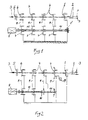
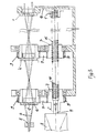
- a fixed guide 1 is provided with bores arranged concentrically to a central axis for receiving single wires 2 is provided.
- the individual wires 2 are seen at substantially equal intervals in the direction of pull is indicated by arrows 3, storage disks 4 downstream of the fixed guide 1, the likewise with bores arranged concentrically to the axis of rotation of the storage disks 4 are provided for receiving the individual wires 2.
- the storage disks are 4 and one Stranding disc 6 can be driven in changing directions.
- a rope guide 5 is provided, through which the rope is subtracted.
- the storage disks 4 and the stranding disk 6 are each driven via a transmission element 9, e.g. a belt through the drive pulleys 7, which are connected to a motor 8 are coupled.
- a transmission element 9 e.g. a belt through the drive pulleys 7, which are connected to a motor 8 are coupled.
- a torsion spring 15 is provided as a coupling element in both embodiments, which in the embodiment according to FIG. 1 in the area of a fixed guide 1 'on one Frame part is fixed.
- the torsion spring 15 is only for part of the Traction sheaves 7 are provided, namely with the two closest to the motor 8 Traction sheaves connected.
- the traction sheaves 7 are in both embodiments on the belt 9 with the Storage disks 4 or coupled with the stranding disk 6. All can with the Torsion spring 15 coupled traction sheaves 7 with the associated storage disks 4 or Stranding disc 6 an identical translation can be provided.
- the two, the fixed guide 1 are next Traction sheaves 7 connected to each other via a rigid shaft 10, which in turn at 16 the torsion spring 15 is coupled.
- Traction sheaves 7 are opposite Translation of the two traction sheaves 7 closer to the motor 8 to the associated storage disks 4 different translations for the storage disks assigned to them 4 provided.
- a stop 17 is provided for the angle of rotation of the storage disk 4 arranged there, whose positions are created so that this disk 4 in both directions SZ can rotate by the corresponding angle of rotation.
- the difference in the angle of rotation of the next to the fixed guide 1 from the spring or already driven by the spring storage disc 4 and the stranding disc 6 must be the same or be greater than the angle of twist that the stranding disk 6 for acceleration needed. This has the advantage that the motor is brought up to its nominal speed very quickly and the turning range from left to right or vice versa on the stranded material can be kept short.
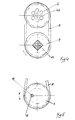
- Fig. 3 From Fig. 3 it can be seen that the motor 8 and its shaft 11 rotatably with the traction sheave 7 is connected, which in turn is also rotatably connected to a torsion spring 15 is.
- the traction sheave 7 associated with the storage disc 4 closest to the motor 8 is also rotatably connected to the torsion spring 15, the torsion spring 15 in one Bracket 1 'is fixed, which is held on a frame-fixed part 13 of the device.
- the torsion spring 15 is by a torsion bar 13 replaced, but the effect and function the same as when using a Torsion spring 9 is.
- Fig. 5 shows an embodiment in which the torsionally elastic shaft by at least one tensioned, stretchable thread or band-shaped element 18 is formed by eccentric arranged bores 19 of the traction sheaves 7 and the engine 8 next traction sheave 7 is set, where appropriate, the eccentricity of the thread-like element penetrate holes in the traction sheaves 7 in the direction of the motor 8 increases.
- the rope or band 18 is preferably via a spring, not shown fixed.
- the rope can also be made of an elastically stretchable material, such as. Rubber, plastic or the like exist, and be held in pretension.
Landscapes
- Engineering & Computer Science (AREA)
- Manufacturing & Machinery (AREA)
- Ropes Or Cables (AREA)
- Insulated Conductors (AREA)
- Transmission Devices (AREA)
- Braiding, Manufacturing Of Bobbin-Net Or Lace, And Manufacturing Of Nets By Knotting (AREA)
- Communication Cables (AREA)
Claims (7)
- Dispositif pour réaliser un assemblage de câble avec un sens de pas alternant (câblage de type SZ) à partir de fils individuels, pour lequel un guidage fixe (1), comportant des perçages destinés à recevoir les fils individuels, et plusieurs disques accumulateurs (4) disposés à distance les uns des autres dans la direction de la traction des fils individuels, pouvant être entraínés dans des sens de rotation alternants, comportant également des perçages pour recevoir les fils individuels à assembler, et un disque d'assemblage (6), qui peuvent être entraínés par l'intermédiaire de disques moteurs (7) et d'organes de transmission (9) sont prévus, et il est prévu un entraínement (8) commun au moins pour une partie des disques moteurs (7), caractérisé par le fait qu'un arbre (13, 15, 18), présentant une élasticité en rotation et ayant une section transversale quelconque, est prévu, arbre qui, à une extrémité, est relié, de façon assujettie en rotation à l'entraínement (8) et qui est fixé de façon stationnaire à son autre extrémité, et que l'arbre (13, 15, 18) présentant une élasticité en torsion est relié de façon assujettie en rotation à au moins une partie des disques moteurs (7).
- Dispositif selon la revendication 1, caractérisé par le fait qu'au moins deux disques moteurs (7) voisins sont reliés ensemble par l'intermédiaire d'un arbre rigide (10), et que ces au moins deux disques moteurs (7) voisins présentent des rapports de transmission différents avec les disques de stockage (7) qui leur sont associés.
- Dispositif selon la revendication 1 ou 2, caractérisé par le fait que l'arbre (15) présentant une élasticité en torsion est maintenu sous une contrainte de traction.
- Dispositif selon la revendication 1, 2 ou 3, caractérisé par le fait que l'arbre présentant une élasticité en torsion est réalisé sous la forme d'un ressort de torsion (15) ou d'une barre de torsion (13), qui est relié de façon assujettie en rotation aux disques moteurs (7).
- Dispositif selon la revendication 4, caractérisé par le fait que la constante d'élasticité du ressort de torsion (15) ou de la barre de torsion (13) va en augmentant en allant dans la direction de l'entraínement (8).
- Dispositif selon la revendication 1, 2 ou 3, caractérisé par le fait que l'arbre présentant une élasticité en torsion est constitué par au moins un élément (18) tendu, sous forme de filament ou de bande extensible, qui est passé à travers des perçages (19), disposés excentriquement, des disques moteurs (7) et est fixé aux disque moteur (7) le plus voisin du moteur (8), où le cas échéant l'excentricité des perçages, traversés par l'élément (18) en forme de filament ou de bande, des disques moteurs (7) va en augmentant en allant en direction du moteur (8).
- Dispositif selon la revendication 6, caractérisé par le fait que l'arbre représentant une élasticité en torsion est constitué par un câble ou une bande, fixé(e) par l'intermédiaire d'un ressort.
Applications Claiming Priority (4)
| Application Number | Priority Date | Filing Date | Title |
|---|---|---|---|
| AT1272/94 | 1994-06-28 | ||
| AT0127294A AT401533B (de) | 1994-06-28 | 1994-06-28 | Vorrichtung zum herstellen einer kabelverseilung mit wechselnder schlagrichtung |
| AT127294 | 1994-06-28 | ||
| PCT/AT1995/000137 WO1996000970A1 (fr) | 1994-06-28 | 1995-06-28 | Dispositif de toronnage de cables en sens alterne |
Publications (2)
| Publication Number | Publication Date |
|---|---|
| EP0767965A1 EP0767965A1 (fr) | 1997-04-16 |
| EP0767965B1 true EP0767965B1 (fr) | 1999-09-29 |
Family
ID=3510296
Family Applications (1)
| Application Number | Title | Priority Date | Filing Date |
|---|---|---|---|
| EP95923111A Expired - Lifetime EP0767965B1 (fr) | 1994-06-28 | 1995-06-28 | Dispositif de toronnage de cables en sens alterne |
Country Status (8)
| Country | Link |
|---|---|
| US (1) | US5799477A (fr) |
| EP (1) | EP0767965B1 (fr) |
| AT (2) | AT401533B (fr) |
| AU (1) | AU2779295A (fr) |
| CA (1) | CA2200861C (fr) |
| DE (1) | DE59506959D1 (fr) |
| ES (1) | ES2139219T3 (fr) |
| WO (1) | WO1996000970A1 (fr) |
Families Citing this family (10)
| Publication number | Priority date | Publication date | Assignee | Title |
|---|---|---|---|---|
| CA2226453C (fr) * | 1998-02-12 | 2006-08-22 | Gerhard Seibert | Dispositif a toronner |
| AT407266B (de) * | 1999-03-24 | 2001-02-26 | Schwechater Kabelwerke | Einrichtung zum zuführen von seilelementen zum verseilkopf einer wechselschlagverseilmaschine |
| US6634164B2 (en) | 2000-11-03 | 2003-10-21 | Kms Kabelmaschinen Und Systeme Gmbh | Apparatus for producing a stranded cable with alternating twist direction made of strand elements |
| WO2002037510A1 (fr) * | 2000-11-03 | 2002-05-10 | Kms Kabelmaschinen Und Systeme Gmbh | Dispositif permettant de produire un cablage a partir d'elements de cablage a sens de cablage alternatif |
| DE10125693B4 (de) * | 2001-05-25 | 2006-03-02 | Illauer, Ulrich, Dipl.-Ing.(TH) | Verfahren für den Betrieb einer Verseilvorrichtung zum besseren Verseilen von Verseilelementen zu einem Verseilprodukt mit abschnittsweise wechselnder Drallrichtung |
| NO328774B1 (no) * | 2008-10-06 | 2010-05-10 | Aker Subsea As | SZ-slagningsmaskin |
| US8161721B2 (en) * | 2009-09-30 | 2012-04-24 | Corning Cable Systems Llc | Cable stranding apparatus employing a hollow-shaft guide member driver |
| US8904743B2 (en) | 2009-09-30 | 2014-12-09 | Corning Cable Systems Llc | Cable stranding apparatus employing a hollow-shaft guide member driver |
| US8161722B2 (en) * | 2009-09-30 | 2012-04-24 | Corning Cable Systems Llc | Cable stranding methods employing a hollow-shaft guide member driver |
| EP2918533B1 (fr) * | 2014-03-10 | 2018-01-03 | SUPERBA (Société par Actions Simplifiée) | Dispositif de génération d'une fausse torsion au niveau d'un toron |
Family Cites Families (12)
| Publication number | Priority date | Publication date | Assignee | Title |
|---|---|---|---|---|
| GB990691A (en) * | 1961-10-12 | 1965-04-28 | Anaconda Wire & Cable Co | Improvements in electric cable, method and apparatus for stranding same |
| GB1180452A (en) * | 1967-11-01 | 1970-02-04 | British Insulated Callenders | Improvements in or relating to the Manufacture of Electric Cables |
| AU3212571A (en) * | 1970-08-13 | 1973-02-15 | Dunlop Australia Limited | Improvements in reinforced articles |
| CA1113806A (fr) * | 1979-12-19 | 1981-12-08 | Bretislav P. Zuber | Methode de toronnage de fils |
| DE8030858U1 (de) * | 1980-11-14 | 1982-04-01 | Siemens AG, 1000 Berlin und 8000 München | Vorrichtung zum SZ-Verseilen mit einem rohrförmigen Führungs- und Speicherkörper |
| DE3211260A1 (de) * | 1982-03-25 | 1983-09-29 | Siemens AG, 1000 Berlin und 8000 München | Antriebseinrichtung fuer verseilkoepfe einer sz-verseilmaschine |
| US4429519A (en) * | 1982-08-30 | 1984-02-07 | Northern Telecom Limited | Forming cable core units |
| DE3536488A1 (de) * | 1985-10-12 | 1987-04-16 | Philips Patentverwaltung | Einrichtung zum reversierenden verseilen (sz-verseilung) mindestens eines verseilelements eines kabels um ein zentralelement |
| JP2763387B2 (ja) * | 1990-07-20 | 1998-06-11 | キヤノン株式会社 | シート搬送装置及び該シート搬送装置を有するプリンタ |
| US5237809A (en) * | 1991-06-17 | 1993-08-24 | Siemens Aktiengesellschaft | Method and apparatus for stranding conductors with changing lay directions |
| DE59309423D1 (de) * | 1992-08-11 | 1999-04-15 | Frisch Gmbh | Vorrichtung zur reversierenden Verseilung von Verseilelementen |
| EP0626523B1 (fr) * | 1993-03-26 | 1996-12-11 | CENTA-ANTRIEBE KIRSCHEY GmbH | Accouplement élastique étagé à deux niveaux |
-
1994
- 1994-06-28 AT AT0127294A patent/AT401533B/de not_active IP Right Cessation
-
1995
- 1995-06-28 AU AU27792/95A patent/AU2779295A/en not_active Abandoned
- 1995-06-28 DE DE59506959T patent/DE59506959D1/de not_active Expired - Lifetime
- 1995-06-28 CA CA002200861A patent/CA2200861C/fr not_active Expired - Fee Related
- 1995-06-28 EP EP95923111A patent/EP0767965B1/fr not_active Expired - Lifetime
- 1995-06-28 ES ES95923111T patent/ES2139219T3/es not_active Expired - Lifetime
- 1995-06-28 WO PCT/AT1995/000137 patent/WO1996000970A1/fr not_active Ceased
- 1995-06-28 US US08/750,685 patent/US5799477A/en not_active Expired - Lifetime
- 1995-06-28 AT AT95923111T patent/ATE185215T1/de active
Also Published As
| Publication number | Publication date |
|---|---|
| CA2200861C (fr) | 2003-08-12 |
| ES2139219T3 (es) | 2000-02-01 |
| US5799477A (en) | 1998-09-01 |
| ATE185215T1 (de) | 1999-10-15 |
| ATA127294A (de) | 1996-02-15 |
| WO1996000970A1 (fr) | 1996-01-11 |
| AU2779295A (en) | 1996-01-25 |
| CA2200861A1 (fr) | 1996-01-11 |
| DE59506959D1 (de) | 1999-11-04 |
| AT401533B (de) | 1996-09-25 |
| EP0767965A1 (fr) | 1997-04-16 |
Similar Documents
| Publication | Publication Date | Title |
|---|---|---|
| EP0767965B1 (fr) | Dispositif de toronnage de cables en sens alterne | |
| EP1367207A2 (fr) | Dispositif d'entraínement en particulier pour toit coulissant de véhicule, ainsi que toit coulissant de véhicule | |
| EP0732476B1 (fr) | Dispositif d'entraínement | |
| DE3138820C2 (de) | Vorrichtung zum Einschieben von Stahlstäben oder dergleichen in ein Hüllrohr zur Bildung eines Bündelzugglieds | |
| DE4241273C2 (de) | Antriebsvorrichtung für die Umwandlung drehender Bewegungen in lineare Bewegungen und umgekehrt | |
| DE19629051A1 (de) | Fördersystem mit Greifklammern | |
| DE2509689C3 (de) | Gegen Zugbeanspruchung widerstandsfähiges Gebilde für Antriebsriemen u.dgl | |
| EP0870428A2 (fr) | Dispositif évacuateur de fumier | |
| WO1999017036A1 (fr) | Mecanisme d'entrainement, notamment commande de portail | |
| DE3309289C2 (de) | Zugfeste Kraftübertragungsanordnung | |
| DE102005052520A1 (de) | Zahnschubkettentrieb | |
| DE10237277A1 (de) | Antriebseinheit für ein Fördermittel | |
| DE19540896A1 (de) | Antriebseinrichtung | |
| DE3414744A1 (de) | Riemen zum uebertragen von bewegung zwischen zwei riemenscheiben | |
| AT501304B1 (de) | Vorrichtung zum herstellen einer verseilung mit wechselnder schlagrichtung | |
| EP1340232B1 (fr) | Dispositif permettant de produire un cablage a partir d'elements de cablage a sens de cablage alternatif | |
| EP0932165A1 (fr) | Dispositif de fabrication d'un câblage | |
| DE102014202967B4 (de) | Zahnriemen mit schlaufenförmig angeordneten Zugsträngen | |
| WO2023078963A1 (fr) | Banc d'essai comportant une pièce à contrôler | |
| DE2100137A1 (fr) | ||
| AT411301B (de) | Vorrichtung zum herstellen einer kabelverseilung aus verseilelementen mit wechselnder schlagrichtung | |
| DE3432770C1 (de) | Seilwinde | |
| EP0867894B1 (fr) | Dispositif de fabrication d'un câblage toronné | |
| DE3035214A1 (de) | Seil bzw. tau sowie verfahren und vorrichtung zum herstellen desselben | |
| AT404265B (de) | Verfahren zum herstellen einer kabelverseilung |
Legal Events
| Date | Code | Title | Description |
|---|---|---|---|
| PUAI | Public reference made under article 153(3) epc to a published international application that has entered the european phase |
Free format text: ORIGINAL CODE: 0009012 |
|
| 17P | Request for examination filed |
Effective date: 19970128 |
|
| AK | Designated contracting states |
Kind code of ref document: A1 Designated state(s): AT BE CH DE DK ES FR GB GR IE IT LI LU MC NL PT SE |
|
| AX | Request for extension of the european patent |
Free format text: LT PAYMENT 970128;LV PAYMENT 970128;SI PAYMENT 970128 |
|
| 17Q | First examination report despatched |
Effective date: 19970916 |
|
| GRAG | Despatch of communication of intention to grant |
Free format text: ORIGINAL CODE: EPIDOS AGRA |
|
| GRAG | Despatch of communication of intention to grant |
Free format text: ORIGINAL CODE: EPIDOS AGRA |
|
| GRAH | Despatch of communication of intention to grant a patent |
Free format text: ORIGINAL CODE: EPIDOS IGRA |
|
| GRAH | Despatch of communication of intention to grant a patent |
Free format text: ORIGINAL CODE: EPIDOS IGRA |
|
| GRAA | (expected) grant |
Free format text: ORIGINAL CODE: 0009210 |
|
| AK | Designated contracting states |
Kind code of ref document: B1 Designated state(s): AT BE CH DE DK ES FR GB GR IE IT LI LU MC NL PT SE |
|
| AX | Request for extension of the european patent |
Free format text: LT PAYMENT 19970128;LV PAYMENT 19970128;SI PAYMENT 19970128 |
|
| LTIE | Lt: invalidation of european patent or patent extension | ||
| PG25 | Lapsed in a contracting state [announced via postgrant information from national office to epo] |
Ref country code: GR Free format text: LAPSE BECAUSE OF NON-PAYMENT OF DUE FEES Effective date: 19990929 |
|
| REF | Corresponds to: |
Ref document number: 185215 Country of ref document: AT Date of ref document: 19991015 Kind code of ref document: T |
|
| REG | Reference to a national code |
Ref country code: CH Ref legal event code: EP |
|
| REF | Corresponds to: |
Ref document number: 59506959 Country of ref document: DE Date of ref document: 19991104 |
|
| REG | Reference to a national code |
Ref country code: IE Ref legal event code: FG4D Free format text: GERMAN |
|
| ITF | It: translation for a ep patent filed | ||
| PG25 | Lapsed in a contracting state [announced via postgrant information from national office to epo] |
Ref country code: DK Free format text: LAPSE BECAUSE OF FAILURE TO SUBMIT A TRANSLATION OF THE DESCRIPTION OR TO PAY THE FEE WITHIN THE PRESCRIBED TIME-LIMIT Effective date: 19991229 |
|
| REG | Reference to a national code |
Ref country code: CH Ref legal event code: NV Representative=s name: BRAUN & PARTNER PATENT-, MARKEN-, RECHTSANWAELTE |
|
| ET | Fr: translation filed | ||
| GBT | Gb: translation of ep patent filed (gb section 77(6)(a)/1977) |
Effective date: 20000105 |
|
| REG | Reference to a national code |
Ref country code: ES Ref legal event code: FG2A Ref document number: 2139219 Country of ref document: ES Kind code of ref document: T3 |
|
| REG | Reference to a national code |
Ref country code: PT Ref legal event code: SC4A Free format text: AVAILABILITY OF NATIONAL TRANSLATION Effective date: 19991228 |
|
| PG25 | Lapsed in a contracting state [announced via postgrant information from national office to epo] |
Ref country code: LU Free format text: LAPSE BECAUSE OF NON-PAYMENT OF DUE FEES Effective date: 20000628 |
|
| PG25 | Lapsed in a contracting state [announced via postgrant information from national office to epo] |
Ref country code: MC Free format text: THE PATENT HAS BEEN ANNULLED BY A DECISION OF A NATIONAL AUTHORITY Effective date: 20000630 Ref country code: BE Free format text: LAPSE BECAUSE OF NON-PAYMENT OF DUE FEES Effective date: 20000630 |
|
| PG25 | Lapsed in a contracting state [announced via postgrant information from national office to epo] |
Ref country code: IE Free format text: LAPSE BECAUSE OF NON-PAYMENT OF DUE FEES Effective date: 20000719 |
|
| PLBE | No opposition filed within time limit |
Free format text: ORIGINAL CODE: 0009261 |
|
| STAA | Information on the status of an ep patent application or granted ep patent |
Free format text: STATUS: NO OPPOSITION FILED WITHIN TIME LIMIT |
|
| REG | Reference to a national code |
Ref country code: IE Ref legal event code: FD4D |
|
| 26N | No opposition filed | ||
| BERE | Be: lapsed |
Owner name: BERGSMANN LUDWIG Effective date: 20000630 |
|
| REG | Reference to a national code |
Ref country code: GB Ref legal event code: IF02 |
|
| REG | Reference to a national code |
Ref country code: GB Ref legal event code: 732E |
|
| REG | Reference to a national code |
Ref country code: PT Ref legal event code: PC4A Owner name: ROSENDAHL MASCHINEN GMBH, AT Effective date: 20060907 |
|
| REG | Reference to a national code |
Ref country code: FR Ref legal event code: TP |
|
| PGFP | Annual fee paid to national office [announced via postgrant information from national office to epo] |
Ref country code: ES Payment date: 20120628 Year of fee payment: 18 |
|
| PGFP | Annual fee paid to national office [announced via postgrant information from national office to epo] |
Ref country code: AT Payment date: 20120620 Year of fee payment: 18 |
|
| PGFP | Annual fee paid to national office [announced via postgrant information from national office to epo] |
Ref country code: SE Payment date: 20130620 Year of fee payment: 19 Ref country code: GB Payment date: 20130620 Year of fee payment: 19 Ref country code: DE Payment date: 20130621 Year of fee payment: 19 Ref country code: CH Payment date: 20130621 Year of fee payment: 19 |
|
| PGFP | Annual fee paid to national office [announced via postgrant information from national office to epo] |
Ref country code: NL Payment date: 20130620 Year of fee payment: 19 Ref country code: PT Payment date: 20130617 Year of fee payment: 19 Ref country code: FR Payment date: 20130703 Year of fee payment: 19 |
|
| PGFP | Annual fee paid to national office [announced via postgrant information from national office to epo] |
Ref country code: IT Payment date: 20130622 Year of fee payment: 19 |
|
| REG | Reference to a national code |
Ref country code: DE Ref legal event code: R119 Ref document number: 59506959 Country of ref document: DE |
|
| REG | Reference to a national code |
Ref country code: PT Ref legal event code: MM4A Free format text: LAPSE DUE TO NON-PAYMENT OF FEES Effective date: 20141229 |
|
| REG | Reference to a national code |
Ref country code: NL Ref legal event code: V1 Effective date: 20150101 |
|
| PG25 | Lapsed in a contracting state [announced via postgrant information from national office to epo] |
Ref country code: PT Free format text: LAPSE BECAUSE OF NON-PAYMENT OF DUE FEES Effective date: 20141229 Ref country code: SE Free format text: LAPSE BECAUSE OF NON-PAYMENT OF DUE FEES Effective date: 20140629 |
|
| REG | Reference to a national code |
Ref country code: CH Ref legal event code: PL |
|
| REG | Reference to a national code |
Ref country code: SE Ref legal event code: EUG |
|
| REG | Reference to a national code |
Ref country code: AT Ref legal event code: MM01 Ref document number: 185215 Country of ref document: AT Kind code of ref document: T Effective date: 20140628 |
|
| GBPC | Gb: european patent ceased through non-payment of renewal fee |
Effective date: 20140628 |
|
| REG | Reference to a national code |
Ref country code: FR Ref legal event code: ST Effective date: 20150227 |
|
| PG25 | Lapsed in a contracting state [announced via postgrant information from national office to epo] |
Ref country code: NL Free format text: LAPSE BECAUSE OF NON-PAYMENT OF DUE FEES Effective date: 20150101 |
|
| REG | Reference to a national code |
Ref country code: DE Ref legal event code: R119 Ref document number: 59506959 Country of ref document: DE Effective date: 20150101 |
|
| PG25 | Lapsed in a contracting state [announced via postgrant information from national office to epo] |
Ref country code: LI Free format text: LAPSE BECAUSE OF NON-PAYMENT OF DUE FEES Effective date: 20140630 Ref country code: DE Free format text: LAPSE BECAUSE OF NON-PAYMENT OF DUE FEES Effective date: 20150101 Ref country code: IT Free format text: LAPSE BECAUSE OF NON-PAYMENT OF DUE FEES Effective date: 20140628 Ref country code: CH Free format text: LAPSE BECAUSE OF NON-PAYMENT OF DUE FEES Effective date: 20140630 |
|
| PG25 | Lapsed in a contracting state [announced via postgrant information from national office to epo] |
Ref country code: GB Free format text: LAPSE BECAUSE OF NON-PAYMENT OF DUE FEES Effective date: 20140628 Ref country code: AT Free format text: LAPSE BECAUSE OF NON-PAYMENT OF DUE FEES Effective date: 20140628 Ref country code: FR Free format text: LAPSE BECAUSE OF NON-PAYMENT OF DUE FEES Effective date: 20140630 |
|
| REG | Reference to a national code |
Ref country code: PT Ref legal event code: MM4A Free format text: MAXIMUM VALIDITY LIMIT REACHED Effective date: 20150628 |
|
| REG | Reference to a national code |
Ref country code: ES Ref legal event code: FD2A Effective date: 20150724 |
|
| PG25 | Lapsed in a contracting state [announced via postgrant information from national office to epo] |
Ref country code: ES Free format text: LAPSE BECAUSE OF NON-PAYMENT OF DUE FEES Effective date: 20140629 Ref country code: PT Free format text: LAPSE BECAUSE OF EXPIRATION OF PROTECTION Effective date: 20150707 |
|
| PG25 | Lapsed in a contracting state [announced via postgrant information from national office to epo] |
Ref country code: PT Free format text: LAPSE BECAUSE OF EXPIRATION OF PROTECTION Effective date: 20140628 |