EP0768024A1 - Faucheuse - Google Patents
Faucheuse Download PDFInfo
- Publication number
- EP0768024A1 EP0768024A1 EP96118034A EP96118034A EP0768024A1 EP 0768024 A1 EP0768024 A1 EP 0768024A1 EP 96118034 A EP96118034 A EP 96118034A EP 96118034 A EP96118034 A EP 96118034A EP 0768024 A1 EP0768024 A1 EP 0768024A1
- Authority
- EP
- European Patent Office
- Prior art keywords
- air
- duct
- machine according
- grass
- machine
- Prior art date
- Legal status (The legal status is an assumption and is not a legal conclusion. Google has not performed a legal analysis and makes no representation as to the accuracy of the status listed.)
- Withdrawn
Links
Images


Classifications
-
- A—HUMAN NECESSITIES
- A01—AGRICULTURE; FORESTRY; ANIMAL HUSBANDRY; HUNTING; TRAPPING; FISHING
- A01D—HARVESTING; MOWING
- A01D34/00—Mowers; Mowing apparatus of harvesters
- A01D34/01—Mowers; Mowing apparatus of harvesters characterised by features relating to the type of cutting apparatus
- A01D34/412—Mowers; Mowing apparatus of harvesters characterised by features relating to the type of cutting apparatus having rotating cutters
- A01D34/63—Mowers; Mowing apparatus of harvesters characterised by features relating to the type of cutting apparatus having rotating cutters having cutters rotating about a vertical axis
- A01D34/71—Mowers; Mowing apparatus of harvesters characterised by features relating to the type of cutting apparatus having rotating cutters having cutters rotating about a vertical axis with means for discharging mown material
-
- A—HUMAN NECESSITIES
- A01—AGRICULTURE; FORESTRY; ANIMAL HUSBANDRY; HUNTING; TRAPPING; FISHING
- A01D—HARVESTING; MOWING
- A01D43/00—Mowers combined with apparatus performing additional operations while mowing
- A01D43/06—Mowers combined with apparatus performing additional operations while mowing with means for collecting, gathering or loading mown material
- A01D43/077—Mowers combined with apparatus performing additional operations while mowing with means for collecting, gathering or loading mown material with auxiliary means, e.g. fans, for transporting the mown crop
- A01D43/0775—Mowers combined with apparatus performing additional operations while mowing with means for collecting, gathering or loading mown material with auxiliary means, e.g. fans, for transporting the mown crop for airborne lawn-mowers
-
- A—HUMAN NECESSITIES
- A01—AGRICULTURE; FORESTRY; ANIMAL HUSBANDRY; HUNTING; TRAPPING; FISHING
- A01D—HARVESTING; MOWING
- A01D2101/00—Lawn-mowers
-
- Y—GENERAL TAGGING OF NEW TECHNOLOGICAL DEVELOPMENTS; GENERAL TAGGING OF CROSS-SECTIONAL TECHNOLOGIES SPANNING OVER SEVERAL SECTIONS OF THE IPC; TECHNICAL SUBJECTS COVERED BY FORMER USPC CROSS-REFERENCE ART COLLECTIONS [XRACs] AND DIGESTS
- Y10—TECHNICAL SUBJECTS COVERED BY FORMER USPC
- Y10S—TECHNICAL SUBJECTS COVERED BY FORMER USPC CROSS-REFERENCE ART COLLECTIONS [XRACs] AND DIGESTS
- Y10S56/00—Harvesters
- Y10S56/08—Air gathering
Definitions
- grass cutting machine is used to include domestic lawn mowers, grass cutting machines for cutting larger areas of grass such as sports fields and parkland as well as grass verge cutting equipment.
- Type (1) machines may be supported relative to ground datum by a cushion of air (commonly called a hover machine), by wheels (commonly called a wheeled rotary machine) or a combination thereof.
- a rear roller may also be used in order to produce a striped effect upon cut grass.
- Type (2) is normally supported on a combination of wheels and rollers.
- a type (2) machine which is supported on a cushion of air.
- a lawn mower of the type which in operation is supported by a cushion of air and has a knife rotatable about a vertical axis and a fan wheel rotatable about the same axis, the fan wheel and the knife being shrouded by a hood, the mower having a rim around the hood and the hood having one or more than one opening for air to the air cushion, characterized in that at least a part of the air stream to the fan wheel before reaching the fan wheel is used to pick up and transport grass, leaves and the like from the ground to a collecting chamber in the mower, the collecting chamber having means for separating grass from air.
- a grass cutting machine comprises a grass cutter, a driving source for driving the grass cutter, means for supporting the machine above ground datum, a device fro collecting grass cut by cutter, a source for establishing a flow of air, the device for collecting cut grass comprising a duct for directing cut grass entrained in a stream or air from the said source and from:
- a grass cutting machine comprises a grass cutter, a driving source for driving the grass cutter, means for supporting the machine above ground datum, a device for collecting grass cut by cutter, a source for establishing a flow of air, the device for collecting cut grass comprising a duct or directing cut grass entrained in a stream of air from the said source and from:
- Collection of cut grass and other debris such as leaves is achieved by directing the stream of air through each air outlet as discussed below.
- Each air outlet may or may not, as hereinafter discussed, include a generally convexly shaped air flow control surface.
- each aperture includes an air flow control surface
- at least a portion of the air flow follows the contour of the air flow control surface by virtue of the boundary layer effect.
- a streamlined flow of air over the air flow control surface results, and at least a major portion of the air flow follows the air flow control surface and enters said duct.
- any such cut grass and loose material is enhanced by the fact that any such material will be rear to one particular region of the air flow control surface and the air thus increases speed in the gap between this one particular region and the material, causing a drop in air pressure in the gap, which drop in pressure pulls the loose material towards the air flow control surface, i.e. the material is lifted from the ground and into the duct via the collection mouth.
- the cut grass and loose material is then as indicated above passed along the duct to a collection container at the down stream region of the duct, by the air flow, and as the duct is merely a passage with no fan or other auxiliary component causing at least a partial obstruction or a tortuous flow path, a relatively smooth path which facilitates the collection of a large variety of shapes and sizes of loose material.
- the duct may be furnished with outwardly flaring front and rear edge regions, each of which edge region is curved and ends in an air flow outlet.
- Each air flow outlet is connected to a motor driven fan or pump with the outlet designed so as to direct a flow of air at an inclined angle to the longitudinal axis of the duct, substantially along a smoothly curved surface, into the duct, part of the outlet merging with the smoothly curved surface and said smoothly curved surface merely merging with the continuing as the inside wall of the duct.
- the front and rear edge regions of the collection mouth may be provided with curved surfaces and associated air flow outlets, solely the front or rear edge region may be so designed or alternatively one or other side edge regions may be additionally or alternatively so designed, as is required.
- the collection container may be a disposable bag which can be easily detachably attached to the other end region of the duct with a filter outlet allowing the air flow to escape adjacent to the container, or alternatively a loose-woven bag may form the collection container obviating the need for a filter outlet.
- an elongate duct 1 presents a generally smooth internal surface for the passage of collected material there through from a collection mouth 2 disposed at an upstream end of the duct.
- the cross sectional shape of the duct 1 may be circular, rectangular, elliptical or polygonal.
- a plenum chamber 4 is constructed to at least partially surround the duct 1 and serves to direct pressure air in the direction of arrows A to an air outlet aperture 3. From Figure 1 it will be seen that the collection mouth is furnished with two generally aerofoil shaped portions 5 and 6 and that the nose of aerofoil portion 6 constitutes a generally convexly shaped air flow control surface which defines at least a portion of the air outlet aperture 3 together with a further generally convexly curved confronting number 7.
- the shape of the air outlet aperture 3 or at least those surfaces leading to the aperture are arranged to direct an air flow generally over the nose of the aerofoil section 6 so as to cause the air to flow along and against the respective curved surfaces. Due to the boundary layer effect and the provision of a smoothly curved air flow control surface, laminar and streamed lined air flow results so that a major part of the air from the outlet follows the profile of the curved surfaces into the duct, the remaining air disturbing any loose material such as grass cuttings located beneath the collection mouth 2 and facilitating entrainment of this loose material into the air flow and along the duct 1 in the direction of arrows B for collection by a collecting device.
- a plurality of air outlet apertures 3 may be disposed around the collection mouth in which case the plenum chamber 4 totally surrounds the elongate duct 1 and the collection mouth as shown in Figure 1A in which like parts bear the same reference numbers as in Figure 1. Entrainment of grass cuttings and other loose material into the elongate duct 1 is improved by the fact that the material will be closer to one part of the aerofoil sections mainly portions 5A and 6A than another.
- Figure 1B is a modification Figure 1A and shows an air outlet Y, extending around the total internal periphery of the collection mouth 2.
- the air outlet Y may consist of a plurality of individual air outlet apertures spaced around the collection mouth.
- the outer 4A and the inner 4B walls of the plenum chamber 4 are so shaped so that air leaving the air outlet Y forms a curtain of air which is directed downstream of the duct 1.
- the inner 4B and outer 4A wall of the plenum chamber 4 may converge towards the aperture Y to produce a venturi effect.
- the angle of exit of the air outlet Y may be varied to direct the curtain of air downstream and outwardly towards the internal wall 4B of the plenum chamber 4 which defines duct 1 or inwardly towards the longitudinal axis of the duct 1.
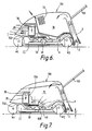
- FIG 2 shows, in longitudinal cross section, a hover-type lawn mower having a hood 100 in which a motor 2 which drives first and second fans 30 and 40 and a cutting blade 50 are coaxially mounted on the motor shaft.
- Air generated by the fan 40 produces a cushion of air for supporting the mower whereas air generated by the fan 30 is led via ducting 60 to a grass collection device described with reference to Figure 1 and disposed abaft the hood 1 as shown.
- Grass cuttings and other litter is, as described with reference to Figure 1, transported downstream within the duct 1 into a removable collector 70 which includes ventilation slots 71.
- a roller 80 is carried by two booms (of which only one is shown) 81 pivotally mounted about a transverse horizontal axis 82 which passes through the motor shaft.
- a handle 83 is supported from roller axle 84 for controlling operation of the mower.
- FIG 3 shows a modification of the mower of Figure 2 in which similar components bear the same reference numbers.
- air from the fan 30 is used for cooling the motor whereas a proportion of the air from the 40 is diverted through ducting 90 towards duct 1 of the collection device described with reference to Figure 1.
- Pressure air reaching the removable collector 70 is drawn through a grating or sieve 72 by the fan 40.
- FIGS 4 and 5 each illustrate a mower having a cylindrical cutter C mounted at the forward end of the mower which is supported on a cushion of air.
- the same reference numbers used in previous Figures are again used for similar components.
- the fan 40 of Figures 4 and 5 are indirectly driven by a belt, gear of other drive line fan the motor 20 which is housed towards the rear of the hood 100.
- the fan 40 of the embodiment of Figure 4 draws external air through a grid 75 to:-
- a roller 80 and handle 83 are mounted to the rear of the hood 100 as indicated.
- the embodiment of Figure 5 differs from that of Figure 4 in that the grass collector is a perforated bag 70A or other unit so that pressure air entering the bag from the collection duct 1 is drawn therefrom via perforations 10B by the fan 40.
- Figures 6 and 7 show two rotary mowers which are supported on four wheels of which one forward wheel W1 and one rearward wheel W2 may be replaced by a split or one piece roller in order to produce a striped effect upon a cut lawn.
- the cutting blade 50 and fan 40 are coaxially mounted on a common vertical shaft which is indirectly driven by the motor 20.
- a cooling motor fan 30 mounted above the motor serves to augment incoming external air drawn by the fan 40 via inlet I.
- pressure air from the fan 40 is led via ducting 6 to the collection duct 1 in the manner previously described with reference to Figure 2 into collector 70 which includes ventilator slots 71.
- Figure 7 operates on similar principles to that previously described with reference to Figure 5 in that pressure air is drawn from a perforated grass collector bag 70A or other unit via apertures 10B in a portion of the hood 1 above the fan 40.
- the position of collector mouth 2 of the collection duct - dimensions "X" Figure 7 may be raised according to pick-up conditions and the condition of the grass, for example, short or long grass, and wet or dry grass.
- the dimension "X" may be raised by constructing the collection duct 1 as a telescopic unit or means such as a parallel or other linkage or a mechanism for raising/lowering the duct perse may be used. If desired the above means for varying the positions of the collection mouth may be used in any of the machines according to the present invention.
- the mowers of Figures 6 and 7 have, as indicated, a conventional semi-corroded cutting chamber CC formed within a cast or moulded chassis 10D.
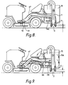
- FIGs 8 and 9 illustrate the use of a collection device in accordance with Figure 1 and constructed as an attachment for a ride-on grass cutting machine.
- grass and other debris exists from the collector duct 1 into a removable collection container 70.
- a parallel linkage mechanism PM permits variation of the position of the collection mouth 2 relative to ground datum.
- Figure 9 operates on a principle similar to that previously described with reference to Figures 5 and 7 in which the collection bag or unit 70A is perforated and air therefrom is drawn back to the fan 40 via ducting 6G.
- the plenum chamber 4 is disposed around a portion of the exterior of the collection duct 1.
- the plenum chamber may totally surround the collection duct as illustrated in Figures 1A and 1B. It will, therefore, be appreciated that the constructions shown in Figures 1, 1A and 1B are interchangeable.
Landscapes
- Life Sciences & Earth Sciences (AREA)
- Environmental Sciences (AREA)
- Harvester Elements (AREA)
- Soil Working Implements (AREA)
- Polysaccharides And Polysaccharide Derivatives (AREA)
- Photoreceptors In Electrophotography (AREA)
- Acyclic And Carbocyclic Compounds In Medicinal Compositions (AREA)
Applications Claiming Priority (3)
| Application Number | Priority Date | Filing Date | Title |
|---|---|---|---|
| GB919103860A GB9103860D0 (en) | 1991-02-25 | 1991-02-25 | Grass cutting machines |
| GB9103860 | 1991-02-25 | ||
| EP92301390A EP0501674B1 (fr) | 1991-02-25 | 1992-02-20 | Tondeuses à gazon |
Related Parent Applications (1)
| Application Number | Title | Priority Date | Filing Date |
|---|---|---|---|
| EP92301390.8 Division | 1992-02-20 |
Publications (1)
| Publication Number | Publication Date |
|---|---|
| EP0768024A1 true EP0768024A1 (fr) | 1997-04-16 |
Family
ID=10690507
Family Applications (2)
| Application Number | Title | Priority Date | Filing Date |
|---|---|---|---|
| EP92301390A Expired - Lifetime EP0501674B1 (fr) | 1991-02-25 | 1992-02-20 | Tondeuses à gazon |
| EP96118034A Withdrawn EP0768024A1 (fr) | 1991-02-25 | 1992-02-20 | Faucheuse |
Family Applications Before (1)
| Application Number | Title | Priority Date | Filing Date |
|---|---|---|---|
| EP92301390A Expired - Lifetime EP0501674B1 (fr) | 1991-02-25 | 1992-02-20 | Tondeuses à gazon |
Country Status (12)
| Country | Link |
|---|---|
| US (1) | US5317860A (fr) |
| EP (2) | EP0501674B1 (fr) |
| JP (1) | JPH06113641A (fr) |
| AT (1) | ATE156651T1 (fr) |
| AU (1) | AU660648B2 (fr) |
| CA (1) | CA2061684A1 (fr) |
| DE (1) | DE69221517T2 (fr) |
| FI (1) | FI920825L (fr) |
| GB (1) | GB9103860D0 (fr) |
| NO (1) | NO178011C (fr) |
| NZ (1) | NZ241729A (fr) |
| ZA (1) | ZA921263B (fr) |
Cited By (4)
| Publication number | Priority date | Publication date | Assignee | Title |
|---|---|---|---|---|
| WO2007017658A1 (fr) * | 2005-08-10 | 2007-02-15 | Gmca Pty Ltd | Tondeuse a gazon |
| CN104956840A (zh) * | 2015-07-13 | 2015-10-07 | 苏州金威特工具有限公司 | 一种具有滤网堵塞提示功能的电动割草机 |
| CN107318357A (zh) * | 2017-02-20 | 2017-11-07 | 佛山尘凡环保科技有限公司 | 一种园林用草坪修理机 |
| CN107318353A (zh) * | 2017-02-20 | 2017-11-07 | 佛山尘凡环保科技有限公司 | 一种园林草坪修剪机 |
Families Citing this family (30)
| Publication number | Priority date | Publication date | Assignee | Title |
|---|---|---|---|---|
| GB2254991B (en) * | 1991-04-08 | 1994-11-16 | Atco Qualcast Ltd | Rotary mowers with grass collection |
| GB9123912D0 (en) * | 1991-11-11 | 1992-01-02 | Electrolux Northern | Improvements in and relating to grass-cutting machines |
| GB9214930D0 (en) * | 1992-07-14 | 1992-08-26 | Electrolux Northern | Grass cutting machines |
| GB9301932D0 (en) * | 1993-02-01 | 1993-03-17 | Electrolux Northern | Improvements in and relating to collection devices |
| GB9304952D0 (en) * | 1993-03-11 | 1993-04-28 | Electrolux Northern | Improvements in and relating to grass cutting machines |
| GB9311024D0 (en) * | 1993-05-28 | 1993-07-14 | Electrolux Northern | Improvements in grass-mowing machines |
| GB9322528D0 (en) * | 1993-11-02 | 1993-12-22 | Electrolux Outdoor Prod Ltd | Collection trimmers |
| JP3260271B2 (ja) * | 1996-01-17 | 2002-02-25 | 株式会社共立 | 遊離物収集機 |
| GB2315658A (en) * | 1996-08-01 | 1998-02-11 | Electrolux Outdoor Prod Ltd | Lawnmower |
| GB2315659A (en) * | 1996-08-01 | 1998-02-11 | Electrolux Outdoor Prod Ltd | Lawnmower |
| US5926972A (en) * | 1996-12-16 | 1999-07-27 | Di Peso; Charles C. | Animal grooming apparatus |
| US6336312B1 (en) * | 1997-02-03 | 2002-01-08 | Textron Inc. | Gang-Type rotary lawn mower with multiple rear rollers |
| GB2333685B (en) * | 1998-02-03 | 2000-03-01 | Sabo Maschinenfabrik Gmbh | Lawn mower with collecting device for the cut material |
| GB2334421B (en) * | 1998-02-23 | 2002-11-13 | Electrolux Outdoor Prod Ltd | Lawnmower |
| US7272920B2 (en) * | 2003-02-03 | 2007-09-25 | Wright Manufacturing, Inc. | Grass catcher for lawn mower |
| US7008315B2 (en) * | 2004-04-26 | 2006-03-07 | Redekop Chaff Systems Ltd. | Venting of a combine harvester |
| DE202005017238U1 (de) * | 2005-07-15 | 2006-11-23 | Ettrich, Bruno | Vorrichtung zur Säuberung, insbesondere zur Sandentfernung, von Grasflächen |
| FI20070536L (fi) * | 2007-07-06 | 2009-01-07 | Actioneco Oy | Parannettu leikkuujätteen käsittelylaitteisto |
| US7849665B2 (en) * | 2009-03-23 | 2010-12-14 | Honda Motor Co., Ltd. | Recirculating grass bagging apparatuses and methods |
| JP2011211980A (ja) * | 2010-03-31 | 2011-10-27 | Hitachi Koki Co Ltd | 芝刈機 |
| EP2656719B1 (fr) * | 2012-04-24 | 2014-11-26 | Robert Bosch Gmbh | Gestion de l'écoulement d'air |
| GB2505713B (en) * | 2012-09-11 | 2017-02-08 | Husqvarna Ab | Lawn maintenance apparatus |
| US9351442B1 (en) * | 2012-11-19 | 2016-05-31 | Omar Jesus Cruz | Leaf collection apparatus and method utilizing automated raking, blowing and bagging techniques |
| JP6559113B2 (ja) * | 2016-11-30 | 2019-08-14 | 本田技研工業株式会社 | 電動芝刈機 |
| DE102016124896A1 (de) * | 2016-12-20 | 2018-06-21 | Amazonen-Werke H. Dreyer Gmbh & Co. Kg | Mobile Bearbeitungseinheit |
| WO2019123658A1 (fr) * | 2017-12-22 | 2019-06-27 | 本田技研工業株式会社 | Mécanisme principal de machine de travail |
| US10905047B2 (en) * | 2018-04-26 | 2021-02-02 | Kubota Corporation | Grass mower and flow booster |
| CN109463098B (zh) | 2018-12-25 | 2024-01-02 | 格力博(江苏)股份有限公司 | 动力组件和园林工具 |
| US11140821B2 (en) * | 2019-03-14 | 2021-10-12 | Honda Motor Co., Ltd. | Apparatus and method for cooling lawnmower components |
| CN110771354B (zh) * | 2019-12-06 | 2025-01-28 | 格力博(江苏)股份有限公司 | 动力头及割草机 |
Citations (6)
| Publication number | Priority date | Publication date | Assignee | Title |
|---|---|---|---|---|
| US4081947A (en) * | 1975-08-21 | 1978-04-04 | Canadian General Electric Company Limited | Rotary lawn mower with separate grass pick up |
| EP0003787B1 (fr) | 1978-02-16 | 1981-10-07 | LOCHER & CIE. AG. | Bassin pour l'aération d'eau usée |
| EP0037871A1 (fr) * | 1980-04-15 | 1981-10-21 | Flymo Limited | Dispositif collecteur pour une tondeuse à gazon supportée par un coussin d'air |
| GB2138280A (en) * | 1983-02-28 | 1984-10-24 | Gorenje Muta Tovarna Poljedels | Cleaning apparatus |
| EP0204573A1 (fr) * | 1985-06-05 | 1986-12-10 | Electrolux Northern Limited | Tondeuse à gazon |
| EP0457433A1 (fr) * | 1990-04-17 | 1991-11-21 | Electrolux Outdoor Products Limited | Tondeuse à gazon |
Family Cites Families (7)
| Publication number | Priority date | Publication date | Assignee | Title |
|---|---|---|---|---|
| US1383455A (en) * | 1919-05-05 | 1921-07-05 | William W Farnsworth | Cleaning apparatus |
| GB997528A (en) * | 1964-06-20 | 1965-07-07 | Flymo Ab | Improvements in lawn mowers |
| US3706189A (en) * | 1972-02-04 | 1972-12-19 | Harry T Rutherford | Safety mower and leaf harvester-mulcher |
| DE7609105U1 (de) * | 1976-03-24 | 1977-09-15 | Sukopp, Hans, 7959 Orsenhausen | Mit saugluft arbeitendes aufnahmegeraet fuer staub oder dergleichen |
| US4773205A (en) * | 1986-08-01 | 1988-09-27 | Outboard Marine Corporation | Anti-clogging means for bulk material flow duct |
| GB9004076D0 (en) * | 1990-02-23 | 1990-04-18 | Coathupe John E | Improvements relating to collection devices |
| GB9008569D0 (en) * | 1990-04-17 | 1990-06-13 | Electrolux Northern | Lawn mowers |
-
1991
- 1991-02-25 GB GB919103860A patent/GB9103860D0/en active Pending
-
1992
- 1992-02-20 AT AT92301390T patent/ATE156651T1/de not_active IP Right Cessation
- 1992-02-20 EP EP92301390A patent/EP0501674B1/fr not_active Expired - Lifetime
- 1992-02-20 DE DE69221517T patent/DE69221517T2/de not_active Expired - Fee Related
- 1992-02-20 EP EP96118034A patent/EP0768024A1/fr not_active Withdrawn
- 1992-02-21 CA CA002061684A patent/CA2061684A1/fr not_active Abandoned
- 1992-02-21 ZA ZA921263A patent/ZA921263B/xx unknown
- 1992-02-24 NO NO920733A patent/NO178011C/no unknown
- 1992-02-24 US US07/840,398 patent/US5317860A/en not_active Expired - Fee Related
- 1992-02-25 NZ NZ241729A patent/NZ241729A/en unknown
- 1992-02-25 AU AU11222/92A patent/AU660648B2/en not_active Ceased
- 1992-02-25 JP JP4086686A patent/JPH06113641A/ja active Pending
- 1992-02-25 FI FI920825A patent/FI920825L/fi not_active Application Discontinuation
Patent Citations (7)
| Publication number | Priority date | Publication date | Assignee | Title |
|---|---|---|---|---|
| US4081947A (en) * | 1975-08-21 | 1978-04-04 | Canadian General Electric Company Limited | Rotary lawn mower with separate grass pick up |
| EP0003787B1 (fr) | 1978-02-16 | 1981-10-07 | LOCHER & CIE. AG. | Bassin pour l'aération d'eau usée |
| EP0037871A1 (fr) * | 1980-04-15 | 1981-10-21 | Flymo Limited | Dispositif collecteur pour une tondeuse à gazon supportée par un coussin d'air |
| GB2138280A (en) * | 1983-02-28 | 1984-10-24 | Gorenje Muta Tovarna Poljedels | Cleaning apparatus |
| EP0204573A1 (fr) * | 1985-06-05 | 1986-12-10 | Electrolux Northern Limited | Tondeuse à gazon |
| US4738086A (en) * | 1985-06-05 | 1988-04-19 | Flymo Limited | Hover-type lawn mower |
| EP0457433A1 (fr) * | 1990-04-17 | 1991-11-21 | Electrolux Outdoor Products Limited | Tondeuse à gazon |
Cited By (6)
| Publication number | Priority date | Publication date | Assignee | Title |
|---|---|---|---|---|
| WO2007017658A1 (fr) * | 2005-08-10 | 2007-02-15 | Gmca Pty Ltd | Tondeuse a gazon |
| GB2442170A (en) * | 2005-08-10 | 2008-03-26 | Gmca Pty Ltd | Lawn mower |
| GB2442170B (en) * | 2005-08-10 | 2010-07-07 | Gmca Pty Ltd | Lawn mower |
| CN104956840A (zh) * | 2015-07-13 | 2015-10-07 | 苏州金威特工具有限公司 | 一种具有滤网堵塞提示功能的电动割草机 |
| CN107318357A (zh) * | 2017-02-20 | 2017-11-07 | 佛山尘凡环保科技有限公司 | 一种园林用草坪修理机 |
| CN107318353A (zh) * | 2017-02-20 | 2017-11-07 | 佛山尘凡环保科技有限公司 | 一种园林草坪修剪机 |
Also Published As
| Publication number | Publication date |
|---|---|
| NZ241729A (en) | 1994-09-27 |
| DE69221517T2 (de) | 1998-02-12 |
| CA2061684A1 (fr) | 1992-08-26 |
| ATE156651T1 (de) | 1997-08-15 |
| FI920825A7 (fi) | 1992-08-26 |
| FI920825L (fi) | 1992-08-26 |
| AU660648B2 (en) | 1995-07-06 |
| EP0501674A1 (fr) | 1992-09-02 |
| NO920733L (no) | 1992-08-26 |
| DE69221517D1 (de) | 1997-09-18 |
| NO178011C (no) | 1996-01-10 |
| NO178011B (no) | 1995-10-02 |
| EP0501674B1 (fr) | 1997-08-13 |
| FI920825A0 (fi) | 1992-02-25 |
| JPH06113641A (ja) | 1994-04-26 |
| AU1122292A (en) | 1992-08-27 |
| ZA921263B (en) | 1992-11-25 |
| NO920733D0 (no) | 1992-02-24 |
| GB9103860D0 (en) | 1991-04-10 |
| US5317860A (en) | 1994-06-07 |
Similar Documents
| Publication | Publication Date | Title |
|---|---|---|
| US5317860A (en) | Collection device for grass cutting machines | |
| CA1079981A (fr) | Tondeuse a lames multiples et a collecteur de gazon sans soufflante auxiliaire | |
| CA1109829A (fr) | Tondeuse de gazon | |
| US3757503A (en) | Lawnmower and grass collector | |
| CN101406123A (zh) | 割草机 | |
| EP2042017B1 (fr) | Châssis de tondeuse | |
| EP0443882B1 (fr) | Dispositif collecteur | |
| EP0579386B1 (fr) | Tondeuses à gazon | |
| EP0204573B1 (fr) | Tondeuse à gazon | |
| EP0821869B1 (fr) | Tondeuse à gazon | |
| NL1010999C2 (nl) | Grasmaaier met verzamelinrichting voor het snijsel. | |
| EP0511766A2 (fr) | Tondeuse à gazon | |
| EP0634090A1 (fr) | Améliorations sur et en relation avec des rotofaucheuses | |
| EP0542459A1 (fr) | Améliorations aux tondeuses à gazon | |
| EP0481655B1 (fr) | Tondeuse à gazon | |
| US7736422B2 (en) | Cyclonic separation grassbag apparatuses and methods for mowing machines | |
| EP0821868B1 (fr) | Tondeuse à gazon | |
| GB2505713A (en) | Lawn maintenance apparatus | |
| GB2053643A (en) | Lawn mower | |
| WO2007017658A1 (fr) | Tondeuse a gazon | |
| JP3754137B2 (ja) | ロータリーモアのモアデッキ | |
| EP0510882A1 (fr) | Tondeuse à gazon | |
| EP0937379B1 (fr) | Tondeuse à gazon | |
| JPH0418351Y2 (fr) | ||
| JPH0356172Y2 (fr) |
Legal Events
| Date | Code | Title | Description |
|---|---|---|---|
| PUAI | Public reference made under article 153(3) epc to a published international application that has entered the european phase |
Free format text: ORIGINAL CODE: 0009012 |
|
| AC | Divisional application: reference to earlier application |
Ref document number: 501674 Country of ref document: EP |
|
| AK | Designated contracting states |
Kind code of ref document: A1 Designated state(s): AT BE CH DE DK ES FR GB GR IT LI LU MC NL PT SE |
|
| 17P | Request for examination filed |
Effective date: 19971014 |
|
| 17Q | First examination report despatched |
Effective date: 19990126 |
|
| STAA | Information on the status of an ep patent application or granted ep patent |
Free format text: STATUS: THE APPLICATION IS DEEMED TO BE WITHDRAWN |
|
| 18D | Application deemed to be withdrawn |
Effective date: 19991111 |