EP0768065A1 - Dispositif de traction destiné à la correction d'une mâchoire supérieure - Google Patents
Dispositif de traction destiné à la correction d'une mâchoire supérieure Download PDFInfo
- Publication number
- EP0768065A1 EP0768065A1 EP96115753A EP96115753A EP0768065A1 EP 0768065 A1 EP0768065 A1 EP 0768065A1 EP 96115753 A EP96115753 A EP 96115753A EP 96115753 A EP96115753 A EP 96115753A EP 0768065 A1 EP0768065 A1 EP 0768065A1
- Authority
- EP
- European Patent Office
- Prior art keywords
- upper jaw
- shaft
- slide
- traction apparatus
- base body
- Prior art date
- Legal status (The legal status is an assumption and is not a legal conclusion. Google has not performed a legal analysis and makes no representation as to the accuracy of the status listed.)
- Withdrawn
Links
- 210000003625 skull Anatomy 0.000 claims description 11
- 238000012937 correction Methods 0.000 claims description 8
- 206010061274 Malocclusion Diseases 0.000 claims description 6
- RTAQQCXQSZGOHL-UHFFFAOYSA-N Titanium Chemical compound [Ti] RTAQQCXQSZGOHL-UHFFFAOYSA-N 0.000 claims description 5
- 229910052719 titanium Inorganic materials 0.000 claims description 5
- 239000010936 titanium Substances 0.000 claims description 5
- 206010009269 Cleft palate Diseases 0.000 claims description 3
- 208000006650 Overbite Diseases 0.000 claims description 3
- 210000002050 maxilla Anatomy 0.000 description 3
- 210000000216 zygoma Anatomy 0.000 description 3
- 210000003128 head Anatomy 0.000 description 2
- 210000001847 jaw Anatomy 0.000 description 2
- 238000004873 anchoring Methods 0.000 description 1
- 238000006073 displacement reaction Methods 0.000 description 1
- 210000002850 nasal mucosa Anatomy 0.000 description 1
- 230000000149 penetrating effect Effects 0.000 description 1
- 238000001356 surgical procedure Methods 0.000 description 1
- 230000003313 weakening effect Effects 0.000 description 1
Images
Classifications
-
- A—HUMAN NECESSITIES
- A61—MEDICAL OR VETERINARY SCIENCE; HYGIENE
- A61B—DIAGNOSIS; SURGERY; IDENTIFICATION
- A61B17/00—Surgical instruments, devices or methods
- A61B17/56—Surgical instruments or methods for treatment of bones or joints; Devices specially adapted therefor
- A61B17/58—Surgical instruments or methods for treatment of bones or joints; Devices specially adapted therefor for osteosynthesis, e.g. bone plates, screws or setting implements
- A61B17/60—Surgical instruments or methods for treatment of bones or joints; Devices specially adapted therefor for osteosynthesis, e.g. bone plates, screws or setting implements for external osteosynthesis, e.g. distractors, contractors
- A61B17/66—Alignment, compression or distraction mechanisms
- A61B17/663—Alignment, compression or distraction mechanisms for jaw bones, e.g. subcutaneous distractors with external access
-
- A—HUMAN NECESSITIES
- A61—MEDICAL OR VETERINARY SCIENCE; HYGIENE
- A61C—DENTISTRY; APPARATUS OR METHODS FOR ORAL OR DENTAL HYGIENE
- A61C7/00—Orthodontics, i.e. obtaining or maintaining the desired position of teeth, e.g. by straightening, evening, regulating, separating, or by correcting malocclusions
-
- Y—GENERAL TAGGING OF NEW TECHNOLOGICAL DEVELOPMENTS; GENERAL TAGGING OF CROSS-SECTIONAL TECHNOLOGIES SPANNING OVER SEVERAL SECTIONS OF THE IPC; TECHNICAL SUBJECTS COVERED BY FORMER USPC CROSS-REFERENCE ART COLLECTIONS [XRACs] AND DIGESTS
- Y10—TECHNICAL SUBJECTS COVERED BY FORMER USPC
- Y10S—TECHNICAL SUBJECTS COVERED BY FORMER USPC CROSS-REFERENCE ART COLLECTIONS [XRACs] AND DIGESTS
- Y10S606/00—Surgery
- Y10S606/902—Cortical plate specifically adapted for a particular bone
- Y10S606/903—Cranial and facial plate
- Y10S606/904—Jaw plate
Definitions
- the invention relates to a pulling device for correcting an upper jaw on a skull, for example for eliminating an overbite, cross bite or cleft palate.
- the upper jaw is completely separated from the skull and also the nasal mucosa is separated, the upper jaw is moved forward and mostly re-fixed with titanium plates.
- the present invention has for its object to develop a pulling device mentioned above, in which an outpatient treatment is sufficient and there is no risk of the jaw falling back.
- a base body is provided with elements for attachment to the upper jaw and can be moved in the correction direction.
- the patient himself can adjust the pulling device or readjust it, so that a new visit to the clinic is not necessary.
- the pulling device according to the invention is used to correct the upper jaw towards the front.
- the idea of the invention should also include that a correction of the upper jaw to the rear is possible, in which case corresponding fastening options must then be selected.
- a pulling device can be attached to one side or a pulling device on each side of the upper jaw, so that a uniform displacement of the upper jaw to the front or in exceptional cases to the rear is possible.
- a hook is provided for anchoring the upper jawbone above the last molar to anchor the base body to a shaft.
- the shaft is preferably connected in one piece to the hook via an arch, the arch and hook forming an undercut that receives the cheekbone in the position of use. This exerts a good pull on the cheekbones forward.
- a through hole is provided in the base body or the shaft, in which a slide is inserted, which can be moved by an actuating element.
- This slide can be moved against the direction of correction. This means that the moment the slider is moved, it will the base body or shaft moves in the opposite direction. For this, however, it is necessary that the slide remain as stationary as possible, which is why a flag is assigned to it, which protrudes from the shaft.
- a flag is assigned to it, which protrudes from the shaft.
- a holder is fixed, which connects the flag with another part of the upper jaw or the skull.
- the flag or the slider is indirectly fixed, so that when the actuating element is actuated, it is not the flag or the slider but rather the base body and thus the upper jaw connected to the base body that is moved.
- the holder consists of a wire which is connected at one end to the flag and at the other end to a titanium plate or the like. The latter is then fixed, for example, to another part of the skull or upper jaw via screws.
- the actuating element should be rotatable about its longitudinal axis, which is why it has a threaded section that rotates in the through hole.
- the threaded section has a corresponding external thread
- the through hole has a corresponding internal thread.
- the actuating element rotates freely relative to the slide, so that it can push the slide away in the through hole or pull the base body towards the slide.
- the actuating element on the one hand of the threaded section has a pin which engages in a blind hole at the end in the slide. This pin also turns freely with respect to the slide.
- a rod section is fixed to the threaded section, which has a hexagon head, for example.
- This hexagon head can be attacked by a corresponding tool and the actuating element can be rotated about its longitudinal axis by rotating the tool.
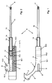
- a traction apparatus R according to the invention, the function of which is described in connection with FIGS. 3 and 4, has a base body 1 according to FIG.
- This base body 1 consists essentially of a shaft 2, to which a hook 4 is connected in one piece via an arc 3.
- This hook 4 forms, together with the arch 3, an undercut 5 with which the pulling device R, as described later, engages behind one upper jaw (maxilla) on one side.
- a through hole 6 is formed in the shaft 2, in which a slide 7 is received, which can be moved in the direction of the arrow x.
- a flag 8 is placed on one end of the slide 7 and protrudes from the shaft 2 or a shaft slot 9.
- This flag 8 has two holes 10.1 and 10.2, which serve to accommodate a holding element described later.
- the slide 7 has an end blind bore 11 into which a pin 12 is inserted.
- the pin 12 rotates freely in the blind hole 11 and is part of an actuating element 13 with which the slide 7 is moved in the direction x.
- the actuating element 13 has a threaded section 14 with an external thread 15, which meshes an internal thread (not shown in more detail) in the through bore 6.
- a rod section 16 adjoins the threaded section 14 and ends with a hexagon 17. If this hexagon 17 is attacked by a corresponding tool, the actuating element 13 can be rotated about its longitudinal axis A, whereby it rotates freely with respect to the slide 7. Via the external thread 15, however, the actuating element 13 screws further into the through bore 6, so that it moves the slide 7 in the direction x, which results in an opposite movement of the base body 1 in the direction x 1 .
- the shaft 2 Transversely to the longitudinal axis A, the shaft 2 has three transverse bores 18.1, 18.2 and 18.3 which serve to receive fastening elements, such as screws, which are not shown in detail.
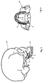
- the pulling device R is applied to an upper jaw 19 of a human skull 20 such that the hook 4 engages behind the upper jaw 19 behind the last molar tooth 21.
- the traction apparatus R is fixed by inserting screws 22 into the Cross bores 18, these screws 22 penetrating the cross bores 18 and being screwed into the upper jaw 19.
- the actuating element 13 runs approximately parallel to the upper jaw 19 or to the molar teeth 21.
- the above-mentioned holder 23 is connected to the flag 8, which can consist for example of a piece of wire.
- This holder 23 is fixed at the other end of the flag 8 at another location on the skull 20, preferably on the cheekbone, it being possible for this to be done using a titanium plate 24.
- the flag 8 shifts in the direction x, which at the same time causes the shaft 2 to be moved in the opposite direction x 1 and to take the upper jaw 19 forward with the hook 4.
- the pressure on the upper jaw 19 causes it to move forward over time, so that, for example, an overbite, cleft palate or cross bite is eliminated.
- the actuating element 13 is rotated further, so that over time the upper jaw 19 yields to this pressure and moves forward.
- the ultimate goal is a correct occlusion between the upper jaw and lower jaw.
Landscapes
- Health & Medical Sciences (AREA)
- Orthopedic Medicine & Surgery (AREA)
- Life Sciences & Earth Sciences (AREA)
- Veterinary Medicine (AREA)
- Surgery (AREA)
- Animal Behavior & Ethology (AREA)
- General Health & Medical Sciences (AREA)
- Public Health (AREA)
- Nuclear Medicine, Radiotherapy & Molecular Imaging (AREA)
- Oral & Maxillofacial Surgery (AREA)
- Epidemiology (AREA)
- Dentistry (AREA)
- Engineering & Computer Science (AREA)
- Biomedical Technology (AREA)
- Heart & Thoracic Surgery (AREA)
- Medical Informatics (AREA)
- Molecular Biology (AREA)
- Orthopedics, Nursing, And Contraception (AREA)
- Surgical Instruments (AREA)
Applications Claiming Priority (2)
| Application Number | Priority Date | Filing Date | Title |
|---|---|---|---|
| DE19538323 | 1995-10-14 | ||
| DE19538323A DE19538323A1 (de) | 1995-10-14 | 1995-10-14 | Zugapparat zur Korrektur eines Oberkiefers |
Publications (1)
| Publication Number | Publication Date |
|---|---|
| EP0768065A1 true EP0768065A1 (fr) | 1997-04-16 |
Family
ID=7774883
Family Applications (1)
| Application Number | Title | Priority Date | Filing Date |
|---|---|---|---|
| EP96115753A Withdrawn EP0768065A1 (fr) | 1995-10-14 | 1996-10-02 | Dispositif de traction destiné à la correction d'une mâchoire supérieure |
Country Status (3)
| Country | Link |
|---|---|
| US (1) | US5885289A (fr) |
| EP (1) | EP0768065A1 (fr) |
| DE (1) | DE19538323A1 (fr) |
Families Citing this family (16)
| Publication number | Priority date | Publication date | Assignee | Title |
|---|---|---|---|---|
| US6139316A (en) * | 1999-01-26 | 2000-10-31 | Sachdeva; Rohit C. L. | Device for bone distraction and tooth movement |
| EP1027868A1 (fr) * | 1999-02-09 | 2000-08-16 | Paul A. Dr. med. Müller | Dispositif de traction destiné à la correction d'une mâchoire supérieure |
| US6423069B1 (en) * | 1999-03-23 | 2002-07-23 | Synthes (Usa) | Orthopedic system having detachable bone anchors |
| US6908469B2 (en) | 2000-10-04 | 2005-06-21 | Synthes (Usa) | Compact maxillary distractor |
| AR033840A1 (es) * | 2000-10-04 | 2004-01-07 | Synthes Ag | Un aparato ortopedico para modificar la distancia entre el maxilar y el cigoma de un paciente |
| US6589250B2 (en) | 2001-11-20 | 2003-07-08 | Stephen A. Schendel | Maxillary distraction device |
| US7892241B2 (en) | 2001-11-20 | 2011-02-22 | Osteomed, L.P. | Method and system for facial osteodistraction using a cannulated device |
| US7621922B2 (en) * | 2001-11-20 | 2009-11-24 | Osteomed L.P. | Facial osteodistraction device |
| US20030233093A1 (en) * | 2002-06-13 | 2003-12-18 | Randall Moles | Osteogenic distraction device |
| US7485121B2 (en) * | 2004-05-04 | 2009-02-03 | Synthes (Usa) | Midface distractor |
| US7875033B2 (en) * | 2004-07-19 | 2011-01-25 | Synthes Usa, Llc | Bone distraction apparatus |
| CN100344265C (zh) * | 2004-07-30 | 2007-10-24 | 广东工业大学 | 镍钛形状记忆合金腭裂修复矫正器及其制造方法 |
| US20060229605A1 (en) * | 2005-03-18 | 2006-10-12 | Olsen Ron A | Adjustable splint for osteosynthesis with incrementing assembly for adjustment in predetermined increments |
| US7507240B2 (en) * | 2005-03-18 | 2009-03-24 | Ron Anthon Olsen | Adjustable splint for osteosynthesis |
| US7731738B2 (en) * | 2005-12-09 | 2010-06-08 | Orthopro, Llc | Cannulated screw |
| RU2380051C1 (ru) * | 2008-12-18 | 2010-01-27 | Муниципальное учреждение Центральная городская клиническая больница №23 | Способ остеосинтеза переломов верхней челюсти |
Citations (2)
| Publication number | Priority date | Publication date | Assignee | Title |
|---|---|---|---|---|
| EP0073455A2 (fr) * | 1981-08-28 | 1983-03-09 | Anton Dr. Härle | Dispositif pour tension avec une plaque ostéosynthétique |
| WO1994022400A1 (fr) * | 1993-03-29 | 1994-10-13 | Robinson Randolph C | Procede et appareil d'ecartement |
Family Cites Families (9)
| Publication number | Priority date | Publication date | Assignee | Title |
|---|---|---|---|---|
| US3473528A (en) * | 1966-04-20 | 1969-10-21 | Sidney Mishkin | Sternal stabilizer |
| US3680553A (en) * | 1970-12-07 | 1972-08-01 | Tallin Bolnitsa Tynismyae | Fixing apparatus for osteosynthesis of fractures of long tubular bones |
| AT378324B (de) * | 1982-09-13 | 1985-07-25 | Streli Elke | Zinkenplatte zur gegenseitigen lagefixierung der knochenteile bei knochenbruechen |
| DE3701533A1 (de) * | 1987-01-21 | 1988-08-04 | Medi System Gmbh | Osteosynthesehilfsmittel |
| DE8807909U1 (de) * | 1988-06-18 | 1988-10-20 | Howmedica GmbH, 2314 Schönkirchen | Knochenplatte, insbesondere Kleinknochenplatte |
| DE3838774A1 (de) * | 1988-11-11 | 1990-05-17 | Mecron Med Prod Gmbh | Gleitlochplatte |
| US5324291A (en) * | 1992-12-21 | 1994-06-28 | Smith & Nephew Richards, Inc. | Bone section reattachment apparatus and method |
| DE4316794C1 (de) * | 1993-05-19 | 1994-10-13 | Joerg Bischof | Vorrichtung zur Distraktion von Knochen |
| US5439465A (en) * | 1994-03-11 | 1995-08-08 | Tumibay; Delfin O. | Bone compression and distraction surgical tool |
-
1995
- 1995-10-14 DE DE19538323A patent/DE19538323A1/de not_active Withdrawn
-
1996
- 1996-10-02 EP EP96115753A patent/EP0768065A1/fr not_active Withdrawn
- 1996-10-11 US US08/730,302 patent/US5885289A/en not_active Expired - Fee Related
Patent Citations (2)
| Publication number | Priority date | Publication date | Assignee | Title |
|---|---|---|---|---|
| EP0073455A2 (fr) * | 1981-08-28 | 1983-03-09 | Anton Dr. Härle | Dispositif pour tension avec une plaque ostéosynthétique |
| WO1994022400A1 (fr) * | 1993-03-29 | 1994-10-13 | Robinson Randolph C | Procede et appareil d'ecartement |
Also Published As
| Publication number | Publication date |
|---|---|
| US5885289A (en) | 1999-03-23 |
| DE19538323A1 (de) | 1997-04-17 |
Similar Documents
| Publication | Publication Date | Title |
|---|---|---|
| DE60007092T2 (de) | Orthopädisches system mit ablösbaren knochenankern | |
| EP1474055B1 (fr) | Lame osseuse | |
| EP1147745B1 (fr) | Dispositif pour l'expansion du palais | |
| DE60022068T2 (de) | Gerät zur einstellung von knochenfragmenten mit einer rücklaufsperre | |
| EP0998237B1 (fr) | Separateur intra-buccal pour la separation de cals dans le maxillaire inferieur | |
| EP0789528A1 (fr) | Endoscope de soutien, notamment pour examens de la region de l'epipharynx, de l'oropharynx et/ou de l'hypopharynx et/ou du larynx | |
| WO2009152633A1 (fr) | Dispositif de fixation externe de fragments d'os | |
| CH686610A5 (de) | Kompressionsimplantat. | |
| WO2005037117A1 (fr) | Systeme pour le traitement a effraction minimale d'une fracture d'un os, notamment d'une fracture proximale de l'humerus ou du femur | |
| DE60114441T2 (de) | Distraktionsvorrichtung für den oberkiefer | |
| DE19538323A1 (de) | Zugapparat zur Korrektur eines Oberkiefers | |
| DE112017003415T5 (de) | Dornfortsatz-laminaklemmvorrichtung | |
| EP3064167B1 (fr) | Kit d'expansion comprenant un dispositif d'expansion ou d'élongation de segments osseux | |
| EP1489979B1 (fr) | Appareil de distraction pour osteogenese | |
| EP1467665B1 (fr) | Dispositif de distraction pour orthodontie ou chirurgie dentaire au niveau du maxillaire inferieur | |
| DE102017012032B4 (de) | Orthodontische Regulierungsvorrichtung | |
| EP3988049B1 (fr) | Dispositif distracteur | |
| EP2023847B1 (fr) | Distracteur palatin oral | |
| DE102006015290A1 (de) | Orthodontische Vorrichtung | |
| EP2727554B1 (fr) | Dispositif orthopédique pour le déplacement vers l'avant de la mâchoire inférieure | |
| DE60117955T2 (de) | Chirurgisches Instrument zur Fixierung gebrochener Gesichtsknochen | |
| EP1027868A1 (fr) | Dispositif de traction destiné à la correction d'une mâchoire supérieure | |
| EP1364621A1 (fr) | Dispositif pour la mise en place et fixation des os et/ou des fragments d'os | |
| EP2768401B1 (fr) | Kit d'implantation mtv | |
| CH693557A5 (de) | Vorrichtungssystem zur Distraktions-Osteogenese. |
Legal Events
| Date | Code | Title | Description |
|---|---|---|---|
| PUAI | Public reference made under article 153(3) epc to a published international application that has entered the european phase |
Free format text: ORIGINAL CODE: 0009012 |
|
| AK | Designated contracting states |
Kind code of ref document: A1 Designated state(s): AT BE CH DE DK ES FI FR GB IT LI NL PT SE |
|
| 17P | Request for examination filed |
Effective date: 19970821 |
|
| 17Q | First examination report despatched |
Effective date: 19990527 |
|
| GRAG | Despatch of communication of intention to grant |
Free format text: ORIGINAL CODE: EPIDOS AGRA |
|
| GRAG | Despatch of communication of intention to grant |
Free format text: ORIGINAL CODE: EPIDOS AGRA |
|
| GRAH | Despatch of communication of intention to grant a patent |
Free format text: ORIGINAL CODE: EPIDOS IGRA |
|
| STAA | Information on the status of an ep patent application or granted ep patent |
Free format text: STATUS: THE APPLICATION IS DEEMED TO BE WITHDRAWN |
|
| 18D | Application deemed to be withdrawn |
Effective date: 20010501 |