EP0768131A1 - Procédé de fabrication d'une large bande de métal - Google Patents
Procédé de fabrication d'une large bande de métal Download PDFInfo
- Publication number
- EP0768131A1 EP0768131A1 EP96115392A EP96115392A EP0768131A1 EP 0768131 A1 EP0768131 A1 EP 0768131A1 EP 96115392 A EP96115392 A EP 96115392A EP 96115392 A EP96115392 A EP 96115392A EP 0768131 A1 EP0768131 A1 EP 0768131A1
- Authority
- EP
- European Patent Office
- Prior art keywords
- nozzle
- gap
- cooling roll
- opening
- thin strip
- Prior art date
- Legal status (The legal status is an assumption and is not a legal conclusion. Google has not performed a legal analysis and makes no representation as to the accuracy of the status listed.)
- Granted
Links
- 239000002184 metal Substances 0.000 title claims abstract description 79
- 229910052751 metal Inorganic materials 0.000 title claims abstract description 79
- 238000004519 manufacturing process Methods 0.000 title claims abstract description 34
- 238000001816 cooling Methods 0.000 claims abstract description 67
- 238000000034 method Methods 0.000 claims description 22
- 238000007711 solidification Methods 0.000 claims description 14
- 230000008023 solidification Effects 0.000 claims description 14
- 230000000694 effects Effects 0.000 claims description 8
- 238000009826 distribution Methods 0.000 description 24
- 238000005266 casting Methods 0.000 description 6
- 230000002093 peripheral effect Effects 0.000 description 6
- 239000000203 mixture Substances 0.000 description 5
- 239000000956 alloy Substances 0.000 description 4
- 229910045601 alloy Inorganic materials 0.000 description 4
- 238000002474 experimental method Methods 0.000 description 4
- 230000006698 induction Effects 0.000 description 4
- 238000002844 melting Methods 0.000 description 4
- 230000008018 melting Effects 0.000 description 4
- 239000000126 substance Substances 0.000 description 4
- 230000001419 dependent effect Effects 0.000 description 3
- 229910000831 Steel Inorganic materials 0.000 description 2
- 230000002265 prevention Effects 0.000 description 2
- 238000012545 processing Methods 0.000 description 2
- 238000004088 simulation Methods 0.000 description 2
- 239000010959 steel Substances 0.000 description 2
- 238000004458 analytical method Methods 0.000 description 1
- 238000004364 calculation method Methods 0.000 description 1
- 238000010276 construction Methods 0.000 description 1
- 238000007796 conventional method Methods 0.000 description 1
- 238000011161 development Methods 0.000 description 1
- 239000000696 magnetic material Substances 0.000 description 1
- 230000008646 thermal stress Effects 0.000 description 1
- 238000012546 transfer Methods 0.000 description 1
Images




Classifications
-
- B—PERFORMING OPERATIONS; TRANSPORTING
- B22—CASTING; POWDER METALLURGY
- B22D—CASTING OF METALS; CASTING OF OTHER SUBSTANCES BY THE SAME PROCESSES OR DEVICES
- B22D11/00—Continuous casting of metals, i.e. casting in indefinite lengths
- B22D11/06—Continuous casting of metals, i.e. casting in indefinite lengths into moulds with travelling walls, e.g. with rolls, plates, belts, caterpillars
- B22D11/0637—Accessories therefor
- B22D11/064—Accessories therefor for supplying molten metal
-
- B—PERFORMING OPERATIONS; TRANSPORTING
- B22—CASTING; POWDER METALLURGY
- B22D—CASTING OF METALS; CASTING OF OTHER SUBSTANCES BY THE SAME PROCESSES OR DEVICES
- B22D11/00—Continuous casting of metals, i.e. casting in indefinite lengths
- B22D11/06—Continuous casting of metals, i.e. casting in indefinite lengths into moulds with travelling walls, e.g. with rolls, plates, belts, caterpillars
- B22D11/0611—Continuous casting of metals, i.e. casting in indefinite lengths into moulds with travelling walls, e.g. with rolls, plates, belts, caterpillars formed by a single casting wheel, e.g. for casting amorphous metal strips or wires
Definitions
- the present invention relates to a method of manufacturing a wide metal thin strip through rapid cooling of a molten metal on the surface of a cooling roll which rotates at high speeds, causing solidification of the molten metal.
- this method comprises arranging a nozzle having a slit-shaped opening, provided on the bottom of a molten metal vessel 2 in the vicinity of a cooling roll 1 which rotates at high speeds. Molten metal is ejected from an opening 3 of the nozzle onto the surface of the cooling roll 1. The molten metal rapidly cools on the cooling roll, causing it to solidify and form a thin strip 4.
- Important operational factors in this technique include the distance between the nozzle and the roll, the peripheral speed of the roll, the ejecting pressure of the molten metal and the gap of the slit-shaped opening of the nozzle.
- Japanese Unexamined Patent Publication No. 53-53525 discloses a similar method of continuously manufacturing a metal strip, which comprises providing a slotted nozzle having a rectangular opening in a position opposite to a moving cooling plate with a distance of from 0.03 to 1 mm in between. Molten metal is fed onto the cooling plate which moves at a prescribed speed, within a range of 100 to 2,000 m/minute, in a state in which an orifice of the nozzle is arranged substantially vertical to the surface of the cooling plate. The molten metal is rapidly cooled by bringing the molten metal into thermal contact to cause solidification.
- the shape of the rectangular opening of the nozzle can be made longer in a direction at right angles to the moving direction of the cooling plate, and hence, the width of the thin strip can be made larger, because, in theory, there is no restriction on the width of the thin strip.
- Japanese Unexamined Patent Publication No. 58-132357 discloses prevention of nozzle deformation by providing a weir in the interior of the nozzle slit.
- the disclosure suggests that it is possible to manufacture a thin strip with a width of 150 mm, having a uniform thickness in the width direction.
- Japanese Unexamined Patent Publication No. 63-220950 and Japanese Unexamined Patent Publication No. 1-170554 disclose a method of manufacturing a thin strip by means of a nozzle having a discontinuous opening in the width direction of the strip, in place of a rectangularly slotted nozzle. By this method, it is possible to manufacture a thin strip having a uniform thickness in the width direction by specifying the shape and arrangement of the opening. In theory, it is possible to increase the width of the thin strip without limitation.
- a deviation of the thin strip thickness in the width direction is caused by not only the slit deformation but by disturbance of the molten metal flow or non-uniform solidification under the effect of: (1) thermal deformation of the roll and the nozzle; (2) temperature of the roll, molten metal and the nozzle; (3) the puddle length due to surface tension of the molten metal; and (4) non-uniformity of the air flow produced by the roll rotation in the width direction of the thin strip. Therefore, thickness deviations in the width direction cannot be completely prevented by prevention of slit deformation alone.
- the present inventors carried out a casting experiment using a nozzle having an opening as shown in Fig. 2, with the goal of achieving uniform thin strip thickness by preventing deformation of the nozzle opening.
- the resultant thin strip displayed a thickness profile, as shown in Fig. 3, similar to that available when using a conventional nozzle having a rectangular opening. More specifically, the results illustrate the difficulty of achieving uniform thickness in the width direction through only preventing slit deformation. The results also illustrate the necessity of taking comprehensive measures to prevent slit deformation.
- Japanese Unexamined Patent Publication Nos. 57-103761, 57-103763 and 62-166056 disclose methods and apparatuses for eliminating the deviation of the molten steel flow rate through either varying the slit gap in the longitudinal direction or by longitudinally varying the bore diameter at the opening comprising a row of small holes.
- the present invention provides a method of manufacturing a thin strip with a uniform width thickness which overcomes the problems described above.
- a first embodiment of the invention comprises the steps of ejecting molten metal from the slit-shaped opening of a nozzle toward the surface of a cooling roll.
- the cooling roll located in the vicinity of the nozzle, rotates at high speeds.
- the resultant rapid cooling causes solidification of the molten metal.
- the opening plane(s) of the nozzle are longitudinally convex.
- the gap between the nozzle opening planes and the cooling roll is smaller at the center, in the longitudinal direction of the nozzle opening plane, and becomes larger toward the ends in the longitudinal direction.
- opening plane refers to the plane or planes, or curved plane, defined by the opening surfaces of the nozzle, as shown in Fig. 5.
- the opening planes are comprised of a center plane, which forms a surface parallel to the cooling roll, and two planes extending from the edges of the center plane which taper away from the cooling roll.
- a second embodiment comprises the steps of ejecting molten metal from the slit-shaped opening of a nozzle toward the surface of the cooling roll.
- the cooling roll rotates at high speeds.
- the resultant rapid cooling of the molten metal causes solidification.
- a third embodiment comprises the steps of ejecting a molten metal from a nozzle having a slit-shaped opening elongated in the axial direction of a cooling roll, toward the surface of the cooling roll.
- the cooling roll is rotating at high speed.
- the resultant rapid cooling of the molten metal causes solidification.
- the solidified thin strip may be collected by conventional methods, such as with windup rollers or similar devices.
- Fig. 1 illustrates the manufacture of thin strips under various conditions. Thin strips were manufactured under various conditions using nozzles having a rectangular opening and having a width within a range of from 50 to 250 mm. The thickness profiles of the resultant thin strips were investigated. The thickness profiles of the thin strips investigated were found to be mostly of convex parabolic shapes, as illustrated in Fig. 4. The results, shown in Fig. 4, were derived from manufacture of 200 mm-wide thin strip under conditions shown in Table 1.
- nozzle gap The relationship between the gap between the nozzle opening plane and the cooling roll (hereinafter referred to as the "nozzle gap") and the thin strip thickness (average in the width direction) was considered with reference to a report by Fiedler, et al. in J. Mater. Sci. 19 (1984) 3229.
- the following relation was derived: (Thickness) ⁇ (nozzle gap) n (n ⁇ 0.25)
- n is a constant dependent on the equipment configuration and operating conditions in the manufacture of a thin strip.
- a manufacturing experiment was carried out which varied the nozzle gap under the manufacturing conditions shown in Table 1. The experiment resulted in a value of n ⁇ .25.
- Adjusting the nozzle gap is an effective means of controlling the thin strip thickness.
- the thickness can be expected to be uniform in the width direction if the nozzle gap is adjusted so that it is smallest at the longitudinal center and becomes larger toward both end portions.
- the manufacturing conditions include g o : 0.12 mm and n ⁇ 0.25.
- Fig. 5 which illustrates a profile of the nozzle opening plane together with the surface of the cooling roll
- the longitudinal center, or the vicinity thereof, of the nozzle opening plane should be convex toward the cooling side.
- the convex shape is preferably formed by a parallel surface 5, which is parallel to the cooling roll surface, and tapered surfaces 6, which extend in a direction more distant from the cooling roll at both sides of the parallel surface 5.
- This construction permits a longitudinal distribution which substantially satisfies the foregoing equation (1) to the nozzle gap, and hence facilitates the working of the nozzle opening plane.
- optimum values can be selected for each of the operating conditions through a simple simulation or the like.
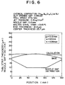
- Figs. 6 to 8 illustrate the thickness profile of a thin strip resulting from manufacture under the operating conditions listed in the individual graphs (center thickness: 25.7 ⁇ m, end thickness: 21 ⁇ m).
- the profile is approximated by a parabola.
- the nozzle gap distribution represents a distribution of the nozzle gap in the width direction which is dependent upon g o , w and h, as shown in the graphs.
- Fig. 6 shows an end basic thickness of 21 ⁇ m and a nozzle gap of 0.19 mm
- Adjusting the gap of the slit shaped opening is an effective means of controlling strip thickness. Under the conditions for the manufacture of a thin strip shown in Fig. 4, for example, the thickness becomes uniform in the width direction by using a nozzle in which the slit-shaped opening gap is small at the longitudinal center and becomes larger toward both ends.
- t(x) ⁇ -4(t ce - t ed )/L 2 ⁇ X 2 + t ce
- the gap of the slit-shaped opening conforms to a longitudinal distribution which satisfies the foregoing equation (2), it is desirable to completely satisfy the equation (2).
- the longitudinal distribution of the gap suffices to comply with the equation (2) by curved working of either one or both sides which form the gap.
- An alloy, in an amount of 250 kg and having a chemical composition comprising 80 at.% Fe, 10 at.% B, 9 at.% Si and 1 at.% C was melted in a high-frequency induction melting furnace.
- the resultant molten metal was heated to 1,325°C and was ejected under an ejecting pressure of 0.17 kgf/cm 2 from a nozzle having a slit-shaped opening gap of 0.75 mm.
- the molten metal was ejected onto the peripheral surface of a cooling roll rotating at 28 m/s, rapidly cooled and solidified.
- the result was a metal thin strip having a width of 200 mm.
- the resultant thin strip possessed a thickness profile illustrated in Fig. 4.
- the thin strip had a difference in thickness of about 4 ⁇ m (convex profile) between the center and the end of the thin strip.
- the resultant thin strip exhibited substantially uniform thickness, measuring 28 ⁇ m, in the width direction, as shown in Fig. 9.
- An alloy, in an amount of 250 kg, having a chemical composition comprising 80 at.% Fe, 10 at.% B, 9 at.% Si and 1 at.% C was melted in a high-frequency induction melting furnace.
- the resultant molten metal was heated to 1,325°C and was ejected under an ejecting pressure of 0.14 kgf/cm 2 from a nozzle having a slit-shaped opening gap of 0.60 mm.
- the molten metal was ejected onto a peripheral surface of a cooling roll rotating at 26 m/s, and rapidly cooled for solidification.
- the resultant metal thin strip had a width of 150 mm.
- the resultant thin strip possessed a thickness profile as illustrated in Fig. 10.
- the thin strip had a difference in thickness of about 3 ⁇ m (convex profile) between the center and the end of the thin strip.
- a thin strip was manufactured in the same manner as above, in accordance with the present invention, using a nozzle having a nozzle opening gap worked in compliance with the foregoing equation (1).
- the resultant thin strip exhibited a substantially uniform thickness, measuring 25 ⁇ m, in the width direction, as shown in Fig. 10.
- An alloy in an amount of 250 kg, having a chemical composition comprising 80 at.% Fe, 10 at.% B, 9 at.% Si and 1 at.% C, was melted in a high-frequency induction melting furnace.
- the resultant molten metal was heated to 1,325°C and was ejected under an ejecting pressure of 0.17 kgf/cm 2 from a nozzle having a slit-shaped opening gap of 0.12 mm.
- the molten metal was ejected onto a peripheral surface of a cooling roll rotating at 28 m/s, and rapidly cooled for solidification.
- the resultant metal thin strip had a width of 200 mm.
- the resultant thin strip possessed a thickness profile as illustrated in Fig. 4.
- the thin strip had a difference in thickness of about 4 ⁇ m (convex profile) between the center and the end of the thin strip.
- a thin strip was manufactured in the same manner as above, in accordance with the present invention, using a nozzle having a nozzle opening gap worked in compliance with the foregoing equation (2).
- the resultant thin strip exhibited a substantially uniform thickness, measuring 28 ⁇ m, in the width direction, as shown in Fig. 11.
- An alloy, in an amount of 250 kg, having a chemical composition comprising 80 at.% Fe, 10 at.% B, 9 at.% Si and 1 at.% C was melted in a high-frequency induction melting furnace.
- the resultant molten metal was heated to 1,325°C and was ejected under an ejecting pressure of 0.14 kgf/cm 2 from a nozzle having a slit-shaped opening gap of 0.10 mm.
- the molten metal was ejected onto a peripheral surface of a cooling roll rotating at 26 m/s, and rapidly cooled for solidification.
- the resultant metal thin strip had a width of 150 mm.
- the resultant thin strip possessed a thickness profile as illustrated in Fig. 12.
- the thin strip had a difference in thickness of about 3 ⁇ m (convex profile) between the center and the end of the thin strip.
- a thin strip was manufactured in the same manner as above, in accordance with the present invention, using a nozzle having a nozzle opening gap worked in compliance with the foregoing equation (2).
- the resultant thin strip exhibited a substantially uniform thickness, measuring 25 ⁇ m, in the width direction, as shown in Fig. 12.
- the opening shape of a nozzle is optimized, thus permitting easy manufacture of a wide thin strip having a uniform thickness in the width direction.
Landscapes
- Engineering & Computer Science (AREA)
- Mechanical Engineering (AREA)
- Continuous Casting (AREA)
Applications Claiming Priority (6)
| Application Number | Priority Date | Filing Date | Title |
|---|---|---|---|
| JP7253231A JP3020850B2 (ja) | 1995-09-29 | 1995-09-29 | 広幅金属薄帯の製造方法および製造装置 |
| JP25323195 | 1995-09-29 | ||
| JP25323295A JP2971372B2 (ja) | 1995-09-29 | 1995-09-29 | 広幅金属薄帯の製造方法および製造装置 |
| JP253231/95 | 1995-09-29 | ||
| JP253232/95 | 1995-09-29 | ||
| JP25323295 | 1995-09-29 |
Publications (2)
| Publication Number | Publication Date |
|---|---|
| EP0768131A1 true EP0768131A1 (fr) | 1997-04-16 |
| EP0768131B1 EP0768131B1 (fr) | 2000-12-06 |
Family
ID=26541091
Family Applications (1)
| Application Number | Title | Priority Date | Filing Date |
|---|---|---|---|
| EP96115392A Expired - Lifetime EP0768131B1 (fr) | 1995-09-29 | 1996-09-25 | Procédé et dispositif de fabrication d'une large bande de métal |
Country Status (3)
| Country | Link |
|---|---|
| US (2) | US5758715A (fr) |
| EP (1) | EP0768131B1 (fr) |
| DE (1) | DE69611144T2 (fr) |
Families Citing this family (3)
| Publication number | Priority date | Publication date | Assignee | Title |
|---|---|---|---|---|
| US8038704B2 (en) * | 2005-07-27 | 2011-10-18 | Paul S. Sherburne | Stent and other objects removal from a body |
| CN102314985B (zh) * | 2011-09-29 | 2013-01-09 | 安泰科技股份有限公司 | 一种铁基非晶合金宽带及其制造方法 |
| CN114472822A (zh) * | 2020-10-27 | 2022-05-13 | 安泰非晶科技有限责任公司 | 一种非晶纳米晶合金带材及其制造方法 |
Citations (5)
| Publication number | Priority date | Publication date | Assignee | Title |
|---|---|---|---|---|
| JPS57103763A (en) * | 1980-12-17 | 1982-06-28 | Matsushita Electric Ind Co Ltd | Nozzle for production of strip |
| JPS57103761A (en) * | 1980-12-17 | 1982-06-28 | Matsushita Electric Ind Co Ltd | Multipored nozzle for production of strip |
| JPS58132357A (ja) * | 1982-02-02 | 1983-08-06 | Nippon Steel Corp | 広巾非晶質合金薄帯の製造用ノズル |
| JPS62166056A (ja) * | 1986-01-16 | 1987-07-22 | Daido Steel Co Ltd | 急冷凝固金属薄帯の製造方法および製造装置 |
| JPS63220950A (ja) * | 1986-06-28 | 1988-09-14 | Nippon Steel Corp | 金属薄帯の製造方法および製造用ノズル |
Family Cites Families (4)
| Publication number | Priority date | Publication date | Assignee | Title |
|---|---|---|---|---|
| US4142571A (en) * | 1976-10-22 | 1979-03-06 | Allied Chemical Corporation | Continuous casting method for metallic strips |
| US4331739A (en) * | 1978-10-10 | 1982-05-25 | Allied Corporation | Amorphous metallic strips |
| US4221257A (en) * | 1978-10-10 | 1980-09-09 | Allied Chemical Corporation | Continuous casting method for metallic amorphous strips |
| JPH0673719B2 (ja) * | 1987-12-26 | 1994-09-21 | 新日本製鐵株式会社 | 金属薄帯の製造方法および製造用ノズル |
-
1996
- 1996-09-23 US US08/717,907 patent/US5758715A/en not_active Expired - Fee Related
- 1996-09-25 DE DE69611144T patent/DE69611144T2/de not_active Expired - Fee Related
- 1996-09-25 EP EP96115392A patent/EP0768131B1/fr not_active Expired - Lifetime
-
1997
- 1997-05-29 US US08/864,892 patent/US5908068A/en not_active Expired - Fee Related
Patent Citations (5)
| Publication number | Priority date | Publication date | Assignee | Title |
|---|---|---|---|---|
| JPS57103763A (en) * | 1980-12-17 | 1982-06-28 | Matsushita Electric Ind Co Ltd | Nozzle for production of strip |
| JPS57103761A (en) * | 1980-12-17 | 1982-06-28 | Matsushita Electric Ind Co Ltd | Multipored nozzle for production of strip |
| JPS58132357A (ja) * | 1982-02-02 | 1983-08-06 | Nippon Steel Corp | 広巾非晶質合金薄帯の製造用ノズル |
| JPS62166056A (ja) * | 1986-01-16 | 1987-07-22 | Daido Steel Co Ltd | 急冷凝固金属薄帯の製造方法および製造装置 |
| JPS63220950A (ja) * | 1986-06-28 | 1988-09-14 | Nippon Steel Corp | 金属薄帯の製造方法および製造用ノズル |
Non-Patent Citations (5)
| Title |
|---|
| H.FIEDLER: "The effect of the main processing parameters on the geometry of amorphous metal ribbons during planar flow casting (PFC)", JOURNAL OF MATERIALS SCIENCE, vol. 19, 1984, pages 3229 - 3235, XP002024227 * |
| PATENT ABSTRACTS OF JAPAN vol. 006, no. 196 (M - 161) 5 October 1982 (1982-10-05) * |
| PATENT ABSTRACTS OF JAPAN vol. 007, no. 246 (M - 253) 2 November 1983 (1983-11-02) * |
| PATENT ABSTRACTS OF JAPAN vol. 012, no. 001 (M - 656) 6 January 1988 (1988-01-06) * |
| PATENT ABSTRACTS OF JAPAN vol. 013, no. 010 (M - 782) 11 January 1989 (1989-01-11) * |
Also Published As
| Publication number | Publication date |
|---|---|
| DE69611144D1 (de) | 2001-01-11 |
| US5758715A (en) | 1998-06-02 |
| EP0768131B1 (fr) | 2000-12-06 |
| DE69611144T2 (de) | 2001-04-05 |
| US5908068A (en) | 1999-06-01 |
Similar Documents
| Publication | Publication Date | Title |
|---|---|---|
| EP1455973B1 (fr) | Dispositif pour controler l'epaisseur d'une couche gazeuse a la surface d'un rouleau de coulee dans un systeme de coulee de bandes a deux rouleaux | |
| EP1634657B1 (fr) | Procede et dispositif de refroidissement controle pour plaque en acier epaisse, et plaque en acier epaisse ainsi obtenue | |
| EP3488947B1 (fr) | Procédé de coulée continue d'acier | |
| EP0768131B1 (fr) | Procédé et dispositif de fabrication d'une large bande de métal | |
| EP1677927B1 (fr) | Texturation de surface de ruban de coulee de machines de coulee continue | |
| JPH10249429A (ja) | 鋼板の冷却装置及び方法 | |
| EP0605094A1 (fr) | Système de refroidissment autonome pour le refroidissement contrôlé d'une bande continue | |
| US4790368A (en) | Method of manufacturing thin metal sheet directly from molten metal and apparatus for manufacturing same | |
| DE60316568T3 (de) | Bandtemperaturregelvorrichtung in einer kontinuierlichen bandgiessanlage | |
| EP0127319B1 (fr) | Appareil de coulée continue pour la production de bandes coulées | |
| JP3526705B2 (ja) | 高炭素鋼の連続鋳造方法 | |
| US4529030A (en) | Electromagnetic stirring method in horizontal continuous casting process | |
| US6161608A (en) | Method and apparatus for producing coated slabs of metal, particularly strips of steel | |
| DE69806136T2 (de) | Vorrichtung und verfahren zum kühlen von walzdraht | |
| JPS6077924A (ja) | 圧延材の冷却方法と装置 | |
| JP3020850B2 (ja) | 広幅金属薄帯の製造方法および製造装置 | |
| EP1064113B1 (fr) | Procede et dispositif pour homogeneiser un film metallique en fusion | |
| JP3023299B2 (ja) | 金属薄帯製造用ノズルの加工方法 | |
| EP0482730A1 (fr) | Appareil pour refroidir une bande en mouvement | |
| SU1611561A1 (ru) | Способ непрерывного лить стальных заготовок и устройство дл его осуществлени | |
| JP3482338B2 (ja) | 圧延鋼板の均一冷却方法 | |
| JP2971372B2 (ja) | 広幅金属薄帯の製造方法および製造装置 | |
| JP3267545B2 (ja) | 連続鋳造方法 | |
| JP2867894B2 (ja) | 連続鋳造方法 | |
| JP2783146B2 (ja) | 鋼板の下面冷却装置 |
Legal Events
| Date | Code | Title | Description |
|---|---|---|---|
| PUAI | Public reference made under article 153(3) epc to a published international application that has entered the european phase |
Free format text: ORIGINAL CODE: 0009012 |
|
| AK | Designated contracting states |
Kind code of ref document: A1 Designated state(s): DE |
|
| 17P | Request for examination filed |
Effective date: 19970428 |
|
| 17Q | First examination report despatched |
Effective date: 19970804 |
|
| GRAG | Despatch of communication of intention to grant |
Free format text: ORIGINAL CODE: EPIDOS AGRA |
|
| RTI1 | Title (correction) |
Free format text: METHOD AND APPARATUS OF MANUFACTURING A WIDE METAL THIN STRIP |
|
| 17Q | First examination report despatched |
Effective date: 19970804 |
|
| GRAG | Despatch of communication of intention to grant |
Free format text: ORIGINAL CODE: EPIDOS AGRA |
|
| GRAH | Despatch of communication of intention to grant a patent |
Free format text: ORIGINAL CODE: EPIDOS IGRA |
|
| GRAH | Despatch of communication of intention to grant a patent |
Free format text: ORIGINAL CODE: EPIDOS IGRA |
|
| GRAA | (expected) grant |
Free format text: ORIGINAL CODE: 0009210 |
|
| AK | Designated contracting states |
Kind code of ref document: B1 Designated state(s): DE |
|
| REF | Corresponds to: |
Ref document number: 69611144 Country of ref document: DE Date of ref document: 20010111 |
|
| EN | Fr: translation not filed | ||
| PLBE | No opposition filed within time limit |
Free format text: ORIGINAL CODE: 0009261 |
|
| STAA | Information on the status of an ep patent application or granted ep patent |
Free format text: STATUS: NO OPPOSITION FILED WITHIN TIME LIMIT |
|
| 26N | No opposition filed | ||
| PGFP | Annual fee paid to national office [announced via postgrant information from national office to epo] |
Ref country code: DE Payment date: 20040923 Year of fee payment: 9 |
|
| PG25 | Lapsed in a contracting state [announced via postgrant information from national office to epo] |
Ref country code: DE Free format text: LAPSE BECAUSE OF NON-PAYMENT OF DUE FEES Effective date: 20060401 |