EP0768174A1 - Procédé et dispositif pour accoupler un cylindre - Google Patents
Procédé et dispositif pour accoupler un cylindre Download PDFInfo
- Publication number
- EP0768174A1 EP0768174A1 EP96115767A EP96115767A EP0768174A1 EP 0768174 A1 EP0768174 A1 EP 0768174A1 EP 96115767 A EP96115767 A EP 96115767A EP 96115767 A EP96115767 A EP 96115767A EP 0768174 A1 EP0768174 A1 EP 0768174A1
- Authority
- EP
- European Patent Office
- Prior art keywords
- pressure
- clutch
- cylinder
- control valve
- working cylinder
- Prior art date
- Legal status (The legal status is an assumption and is not a legal conclusion. Google has not performed a legal analysis and makes no representation as to the accuracy of the status listed.)
- Granted
Links
- 238000000034 method Methods 0.000 title claims description 7
- 238000010168 coupling process Methods 0.000 claims abstract description 17
- 230000008878 coupling Effects 0.000 claims abstract description 9
- 238000005859 coupling reaction Methods 0.000 claims abstract description 9
- 230000006835 compression Effects 0.000 claims description 10
- 238000007906 compression Methods 0.000 claims description 10
- 238000007789 sealing Methods 0.000 claims description 10
- 230000005540 biological transmission Effects 0.000 description 1
- 238000007599 discharging Methods 0.000 description 1
- 238000005553 drilling Methods 0.000 description 1
- 210000003746 feather Anatomy 0.000 description 1
- 230000003993 interaction Effects 0.000 description 1
- 239000003595 mist Substances 0.000 description 1
Images

Classifications
-
- B—PERFORMING OPERATIONS; TRANSPORTING
- B41—PRINTING; LINING MACHINES; TYPEWRITERS; STAMPS
- B41F—PRINTING MACHINES OR PRESSES
- B41F13/00—Common details of rotary presses or machines
- B41F13/008—Mechanical features of drives, e.g. gears, clutches
Definitions
- the invention relates to a method and a device for coupling a cylinder of a rotary printing press to a drive gear according to the preamble of claims 1 and 4.
- DE-Gbm 1 858 031 shows a device for coupling a cylinder of a rotary printing press to a drive gear.
- a cylinder barrel provided with a first clutch disc is pressed against a second, axially adjustable clutch disc by means of a working cylinder. This clutch disc is rigidly connected to the drive gear.
- a disadvantage of this device is that it is not possible to decouple the drive wheel from the cylinder barrel without dismantling the cylinder barrel.
- the invention has for its object to provide a method and an apparatus for coupling a cylinder of a rotary printing press.
- the device according to the invention achieves a gentle, low-wear engagement during a controllable engagement process, since two rotating relative to each other Clutch discs are pressed against each other with reduced force compared to the engaged state.
- the two pressures occurring in a working cylinder are measured by means of a pressure switch and used to display the clutch status.
- This pressure switch can be arranged in the feed line of the working cylinder. This means that there are no problems due to oil mist, data transmission from rotating or axially displaceable parts.
- a control valve used in the device for discharging a certain amount of pressure medium from the working cylinder is small and simple. It is operated directly by the interaction of the clutch discs. It is particularly advantageous that an annular gap formed by the control piston and pressure sleeve discharges a quantity of pressure medium into the open when the control valve is open and at the same time serves as a guide for the control piston.
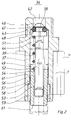
- the device according to the invention is shown in the drawing and is described in more detail below.
- a cylinder of a rotary printing press can be connected to a drive gear 3 on a cylinder journal 1 by means of a switchable clutch 2.
- This switchable clutch 2 consists of a first 6 and a second 4, each annular clutch disc, which are each provided on their opposite plane sides with end teeth 7, 8.
- the spur gears 7, 8 are adapted to one another in such a way that the clutch 2 can only engage in a single position in which the two clutch plates 4, 6 are clearly in relation to one another, ie the clutch 2 is designed as a unique clutch.
- the one clutch disk 4 can be provided with one or more teeth, for example wider teeth or teeth, which differ from the other teeth of the spur teeth 7, 8, and the other associated clutch disk 6 can be provided with tooth gaps adapted thereon.
- One of the two clutch disks 4, 6 is rigidly connected to the cylinder journal 1.
- the left clutch disc 4, which is closest to a cylinder barrel, and a gearwheel 9 for driving further cylinders (not shown) or an inking unit are fastened on the cylinder journal 1 by means of a feather key 11.
- the cylinder is axially displaceable with the clutch disc 4 and the gear 9 for setting the side register.
- the right clutch disc 6 is torsionally rigid, but axially displaceably connected to the drive gear 3.
- the clutch disc 6 on its circumference an external toothing 12 with a width b12, z. B.
- b12 18 mm, which in an introduced into the drive gear 3 internal teeth 13 with a width b13, z. B.
- the drive gear 3 is attached to a hub 14.
- This hub 14 has a bore 16 adapted to the cylinder pin 1, so that the hub 14 with the drive gear 3 is rotatably and axially displaceably mounted on the cylinder pin 1.
- the axial shift which is used to set the circumferential register, takes place by means of an axially displaceable spindle 17, which is mounted in the cylinder journal 1 and is connected to a register setting device (not shown), which is rigidly connected to the drive gear 3 via a disk 18.
- a working cylinder 19 is flanged to this hub 14 of the drive gear 3.
- the working cylinder 19 has an annular, axially displaceable piston 21, which acts on cylindrical pressure pieces 22.
- a plurality, e.g. B. 8 pieces, these pressure pieces 22 are evenly supported in the circumferential direction in bores 23 of the hub 14 and connected by means of screws 24 to the right clutch disc 6.
- the pressure pieces 22 are provided with a collar 26 at their end cooperating with the piston 21. Between this collar 26 and the hub 14 22 compression springs 27 are arranged on the pressure pieces.
- With the working cylinder 19 is a rotary entry 28 connected, which supplies a cylinder space 31 with pressure medium via a bore 29.
- a feed line 32 to the rotary inlet 28 is a not shown, for. B.
- the switching point is set to 5 bar, for example.
- the cylinder space 31 is connected via a bore 33 made in the piston 21 to a line 34 which in turn connects to a control valve 36.
- the control valve 36 is fixedly mounted in the right clutch disc 6 and interacts temporarily with the left clutch disc 4.
- This control valve 36 consists essentially of a housing 37, a control piston 38, a compression spring 39 and a pressure sleeve 41 has provided.
- a second, continuous bore 44 with an inner diameter d44, z. B. d44 6.5 mm.
- the control piston 38 is arranged to be movable in the longitudinal direction.
- This control piston 38 has at its first end a conical sealing head 46, this conical sealing head 46 having an annular circumferential groove 47 for receiving a sealing ring 48, for. B. an O-ring is provided.
- This compression spring 39 presses with its first end against an underside 51 of the sealing head 46 and with its second end against an upper end face 52 of the pressure sleeve 41.
- the bore 53 of the pressure sleeve 41 and the shaft 49 of the control piston 38 form an annular gap 54.
- An outer diameter D41, for. B. D41 6.4 mm, the pressure sleeve 41 is adapted in the region of a shoulder 56 to the inside diameter d44 of the housing 37 in such a way that the pressure sleeve 41 is displaceably mounted in the longitudinal direction.
- an end face 57 of the shoulder 56 serving as a stop
- an end face 58 of a stop sleeve 59 interacts, which is fastened in the bore 44 of the housing 37 to limit the path of the pressure sleeve 41.
- a lower end face 61 of the pressure sleeve 41 protrudes from the housing 37.
- This control valve 36 is mounted in the right clutch disc 6 so that the end face 61 of the pressure sleeve 41 cooperates with the left clutch half 4 in the coupled state.
- pressure medium is supplied to the working cylinder 19 via the rotary inlet 28.
- This pressure medium flows through the line 34 to the control valve 36 and presses the cone-like sealing head 46 of the control piston 38 away from the cone-like depression 43 by the pressure which builds up, so that pressure medium flows through a resulting annular gap.
- This pressure medium escapes through the annular gap 54 of the control piston 38 and the pressure sleeve 41 to the outside.
- This annular gap 54 and the amount of pressure medium supplied to the working cylinder 19 are matched to one another such that a pressure builds up in the working cylinder 19 and the two clutch disks 4, 6 are pressed against one another by means of the pressure pieces 22.
- p1 3.5 bar
- the size of the pressure p1 is preferably 1/3 to 2/3 of the final pressure p2.
- the cylinder is now rotated by means of an auxiliary drive, not shown, so that the two clutch disks 4, 6 pressed onto one another rotate relative to one another.
- the pressure sleeve 41 of the control valve 36 does not touch the left clutch disc 4 and the control valve 36 remains open.
- an electromagnetic valve can also be used.
- This solenoid valve is controlled by means of a sensor which removes the position of the clutch disc 6.
Landscapes
- Engineering & Computer Science (AREA)
- Mechanical Engineering (AREA)
- Hydraulic Clutches, Magnetic Clutches, Fluid Clutches, And Fluid Joints (AREA)
- Inking, Control Or Cleaning Of Printing Machines (AREA)
- Rotary Presses (AREA)
- Mechanical Operated Clutches (AREA)
Applications Claiming Priority (2)
| Application Number | Priority Date | Filing Date | Title |
|---|---|---|---|
| DE19537421 | 1995-10-07 | ||
| DE19537421A DE19537421C1 (de) | 1995-10-07 | 1995-10-07 | Verfahren und Vorrichtung zum Ankuppeln eines Zylinders |
Publications (2)
| Publication Number | Publication Date |
|---|---|
| EP0768174A1 true EP0768174A1 (fr) | 1997-04-16 |
| EP0768174B1 EP0768174B1 (fr) | 2000-01-19 |
Family
ID=7774296
Family Applications (1)
| Application Number | Title | Priority Date | Filing Date |
|---|---|---|---|
| EP96115767A Expired - Lifetime EP0768174B1 (fr) | 1995-10-07 | 1996-10-02 | Procédé et dispositif pour accoupler un cylindre |
Country Status (4)
| Country | Link |
|---|---|
| US (1) | US5701818A (fr) |
| EP (1) | EP0768174B1 (fr) |
| JP (1) | JP2849073B2 (fr) |
| DE (2) | DE19537421C1 (fr) |
Cited By (5)
| Publication number | Priority date | Publication date | Assignee | Title |
|---|---|---|---|---|
| WO1999038690A1 (fr) * | 1998-01-30 | 1999-08-05 | Koenig & Bauer Aktiengesellschaft | Dispositif d'entrainement pour un composant rotatif d'une machine a imprimer |
| EP0933202A3 (fr) * | 1998-01-24 | 2000-03-29 | MAN Roland Druckmaschinen AG | Entraínement d'un appareil de marge |
| WO2002024452A3 (fr) * | 2000-09-20 | 2002-10-17 | Koenig & Bauer Ag | Unite d'impression |
| US6601681B1 (en) | 1998-01-30 | 2003-08-05 | Koenig & Bauer Aktiengesellschaft | Drive mechanism for a rotating component of a printing machine |
| ES2377412A1 (es) * | 2009-04-23 | 2012-03-27 | Comexi, S.A. | Dispositivo de soporte liberable para un extremo de un eje giratorio, aplicable a una máquina impresora. |
Families Citing this family (13)
| Publication number | Priority date | Publication date | Assignee | Title |
|---|---|---|---|---|
| DE19826891A1 (de) * | 1998-06-17 | 1999-12-23 | Heidelberger Druckmasch Ag | Bogenrotationsdruckmaschine |
| DE19961866A1 (de) * | 1999-12-22 | 2001-06-28 | Roland Man Druckmasch | Vorrichtung zur Zufuhr eines Druckmediums zu einem eine Druckform oder ein Gummituch tragenden Zylinder |
| DE19962421C1 (de) | 1999-12-22 | 2001-06-07 | Roland Man Druckmasch | Verfahren und Vorrichtung zum Kuppeln/Entkuppeln eines Zylinders in einer Druckmaschine |
| DE10066068A1 (de) * | 2000-05-17 | 2002-09-26 | Koenig & Bauer Ag | Antrieb eines rotierenden Bauteils |
| DE10152838B4 (de) * | 2000-11-30 | 2013-10-31 | Heidelberger Druckmaschinen Ag | Verfahren zum Betreiben einer Bogenrotationsdruckmaschine und Bogenrotationsdruckmaschine |
| US7156018B2 (en) * | 2001-04-09 | 2007-01-02 | Koenig & Bauer Aktiengesellschaft | Printing couple in a printing machine with a pivotable transfer cylinder |
| ITFI20040226A1 (it) * | 2004-11-08 | 2005-02-08 | Om Futura S P A | Dispositivo e procedimento per la rimozione della camicia dai rulli cliche' in macchine per stampa |
| JP5140265B2 (ja) * | 2005-11-21 | 2013-02-06 | ハイデルベルガー ドルツクマシーネン アクチエンゲゼルシヤフト | 印刷機の回転可能に支承された胴にて作動プロセスを実施するための装置 |
| DE102009005065B4 (de) * | 2008-02-18 | 2021-04-29 | Heidelberger Druckmaschinen Ag | Verfahren und Vorrichtung zum Ein- und Auskuppeln eines Plattenzylinders in einer Bogendruckmaschine |
| DE102008009631A1 (de) * | 2008-02-18 | 2009-08-27 | Heidelberger Druckmaschinen Ag | Vorrichtung zum Ein- und Auskuppeln eines Antriebes an einen Zylinder einer Verarbeitungsmaschine |
| DE102008001651A1 (de) * | 2008-05-08 | 2009-11-12 | Zf Friedrichshafen Ag | Getriebe eines Feuchtwerks |
| US20100122638A1 (en) * | 2008-11-18 | 2010-05-20 | C.G. Bretting Manufacturing Co., Inc. | Flexographic Printing Apparatus And Method |
| DE102009002495A1 (de) * | 2009-04-20 | 2010-10-21 | Manroland Ag | Druckmaschinen-Kupplung und damit ausgerüstete Druckeinheit |
Citations (4)
| Publication number | Priority date | Publication date | Assignee | Title |
|---|---|---|---|---|
| DE396871C (de) * | 1922-06-18 | 1924-06-23 | Karges Hammer Maschinenfabrik | Eintourenkupplung fuer Boerdelmaschinen, Stanzen u. dgl. |
| US4566566A (en) * | 1983-09-19 | 1986-01-28 | Societe Alsacienne De Construction De Material Textile | Device for temporarily uncoupling two coaxial rotating elements |
| US5060776A (en) * | 1988-04-22 | 1991-10-29 | Saab Automobile Aktiebolag | Arrangement for controlling a hydraulically operated friction disc clutch with diaphragm spring |
| US5170708A (en) * | 1992-01-02 | 1992-12-15 | Rdp Marathon Inc. | Register control device for a printing press |
Family Cites Families (7)
| Publication number | Priority date | Publication date | Assignee | Title |
|---|---|---|---|---|
| DE1858031U (de) * | 1962-07-21 | 1962-09-06 | Windmoeller & Hoelscher | Vorrichtung in rotations-druckmaschinen zum tragen eines achslosen klischeezylinders. |
| US3785157A (en) * | 1972-11-24 | 1974-01-15 | Deere & Co | Flow control dump valve |
| FI67675C (fi) * | 1980-09-04 | 1985-05-10 | Frankenthal Ag Albert | Cylinder foer banformiga material bearbetande maskiner |
| US4581979A (en) * | 1983-07-01 | 1986-04-15 | Automotive Products Plc | Shipping and installation restraining clip for master cylinder input member |
| DE4005890A1 (de) * | 1990-02-24 | 1991-09-05 | Bielomatik Leuze & Co | Klischeehuelsen-montagevorrichtung |
| US5105922A (en) * | 1991-04-01 | 1992-04-21 | Dana Corporation | Hydraulic clutch and transmission actuating system |
| DE4214228A1 (de) * | 1992-04-30 | 1993-11-04 | Kba Planeta Ag | Feststelleinrichtung fuer zylinder und druckwerke |
-
1995
- 1995-10-07 DE DE19537421A patent/DE19537421C1/de not_active Expired - Fee Related
-
1996
- 1996-10-02 DE DE59604218T patent/DE59604218D1/de not_active Expired - Lifetime
- 1996-10-02 EP EP96115767A patent/EP0768174B1/fr not_active Expired - Lifetime
- 1996-10-07 US US08/726,684 patent/US5701818A/en not_active Expired - Fee Related
- 1996-10-07 JP JP8266297A patent/JP2849073B2/ja not_active Expired - Fee Related
Patent Citations (4)
| Publication number | Priority date | Publication date | Assignee | Title |
|---|---|---|---|---|
| DE396871C (de) * | 1922-06-18 | 1924-06-23 | Karges Hammer Maschinenfabrik | Eintourenkupplung fuer Boerdelmaschinen, Stanzen u. dgl. |
| US4566566A (en) * | 1983-09-19 | 1986-01-28 | Societe Alsacienne De Construction De Material Textile | Device for temporarily uncoupling two coaxial rotating elements |
| US5060776A (en) * | 1988-04-22 | 1991-10-29 | Saab Automobile Aktiebolag | Arrangement for controlling a hydraulically operated friction disc clutch with diaphragm spring |
| US5170708A (en) * | 1992-01-02 | 1992-12-15 | Rdp Marathon Inc. | Register control device for a printing press |
Cited By (6)
| Publication number | Priority date | Publication date | Assignee | Title |
|---|---|---|---|---|
| EP0933202A3 (fr) * | 1998-01-24 | 2000-03-29 | MAN Roland Druckmaschinen AG | Entraínement d'un appareil de marge |
| WO1999038690A1 (fr) * | 1998-01-30 | 1999-08-05 | Koenig & Bauer Aktiengesellschaft | Dispositif d'entrainement pour un composant rotatif d'une machine a imprimer |
| US6601681B1 (en) | 1998-01-30 | 2003-08-05 | Koenig & Bauer Aktiengesellschaft | Drive mechanism for a rotating component of a printing machine |
| WO2002024452A3 (fr) * | 2000-09-20 | 2002-10-17 | Koenig & Bauer Ag | Unite d'impression |
| US6817292B2 (en) | 2000-09-20 | 2004-11-16 | Koenig & Bauer Aktiengesellschaft | Printing unit |
| ES2377412A1 (es) * | 2009-04-23 | 2012-03-27 | Comexi, S.A. | Dispositivo de soporte liberable para un extremo de un eje giratorio, aplicable a una máquina impresora. |
Also Published As
| Publication number | Publication date |
|---|---|
| DE59604218D1 (de) | 2000-02-24 |
| US5701818A (en) | 1997-12-30 |
| DE19537421C1 (de) | 1997-03-27 |
| JP2849073B2 (ja) | 1999-01-20 |
| EP0768174B1 (fr) | 2000-01-19 |
| JPH09131852A (ja) | 1997-05-20 |
Similar Documents
| Publication | Publication Date | Title |
|---|---|---|
| EP0768174B1 (fr) | Procédé et dispositif pour accoupler un cylindre | |
| EP0435164B1 (fr) | Transformateur rotatif pour introduire de l'air comprimé dans une partie de machine à imprimer en rotation | |
| EP0248917A1 (fr) | Dispositif de réglage de la course du coulisseau dans une presse à arbre à excentrique | |
| EP0239830A2 (fr) | Dispositif de réglage de la position angulaire relative entre une roue dentée et une couronne dentée coaxiale | |
| EP0719640B1 (fr) | Cylindre pour une machine à imprimer rotative | |
| DE2853901C2 (de) | Eindruckvorrichtung für eine Druckmaschine, insbesondere Rotationsdruckmaschine | |
| DE2947242A1 (de) | Hydraulisch betaetigbare reibungskupplung | |
| EP1101538A2 (fr) | Appareil d'extrusion électrique pour cartouches | |
| DE3108249A1 (de) | Dehnspannwerkzeug | |
| EP0993561B1 (fr) | Servo-moteur pour embrayage de vehicule | |
| DE453698C (de) | Walzenlager mit hydraulischer Anpressvorrichtung | |
| DE2802153A1 (de) | Schmitzringverbindung zwischen zwei druckwerkszylindern | |
| DE2450973C3 (de) | Vorrichtung zur Verstellung des Stößelhubes bei Doppelständerpressen mit zwei nebeneinander liegenden Exzenterwellen | |
| WO1999014014A1 (fr) | Dispositif d'entrainement pour plusieurs organes d'une machine | |
| DE10122260B4 (de) | Linearantriebseinrichtung zum Öffnen und Schließen von Formwerkzeugen sowie Aufbringen einer Schließkraft hierauf | |
| CH660055A5 (de) | Einrichtung zur aenderung der ventil- und/oder einspritzsteuerzeiten an einer hubkolbenbrennkraftmaschine. | |
| EP0545004A2 (fr) | Entraînement pour rotatives | |
| DE4209341C2 (de) | Druckluftzuführeinrichtung an Zylindern von Druckmaschinen | |
| DE19746180B4 (de) | Werkzeug und Verfahren zum Einstellen der exzentrischen zeitlichen Position bei Kurbelwellen mit einstellbarem Hub | |
| DE3611243C2 (de) | Vorrichtung zur Zuführung von Energie zu einem Zylinder einer Druckmaschine | |
| DE3337309C2 (de) | Vorrichtung zum Druckan- und abstellen eines auf einen Formzylinder wirkenden Gegendruckzylinders einer Rollen-Rotationsdruckmaschine | |
| DE3813829C2 (fr) | ||
| DE3424539A1 (de) | Kombinierte kupplungs- und bremsvorrichtung mit schleichgangantrieb fuer pressen | |
| DE2626557C3 (de) | Spannvorrichtung, insbesondere Maschinenschraubstock | |
| DD203606A1 (de) | Reibungskupplung und-bremse mit automatischer verschleissnachstellung |
Legal Events
| Date | Code | Title | Description |
|---|---|---|---|
| PUAI | Public reference made under article 153(3) epc to a published international application that has entered the european phase |
Free format text: ORIGINAL CODE: 0009012 |
|
| AK | Designated contracting states |
Kind code of ref document: A1 Designated state(s): CH DE FR GB IT LI SE |
|
| 17P | Request for examination filed |
Effective date: 19971004 |
|
| RAP1 | Party data changed (applicant data changed or rights of an application transferred) |
Owner name: KOENIG & BAUER AKTIENGESELLSCHAFT |
|
| GRAG | Despatch of communication of intention to grant |
Free format text: ORIGINAL CODE: EPIDOS AGRA |
|
| 17Q | First examination report despatched |
Effective date: 19990125 |
|
| GRAG | Despatch of communication of intention to grant |
Free format text: ORIGINAL CODE: EPIDOS AGRA |
|
| GRAH | Despatch of communication of intention to grant a patent |
Free format text: ORIGINAL CODE: EPIDOS IGRA |
|
| GRAH | Despatch of communication of intention to grant a patent |
Free format text: ORIGINAL CODE: EPIDOS IGRA |
|
| GRAA | (expected) grant |
Free format text: ORIGINAL CODE: 0009210 |
|
| ITF | It: translation for a ep patent filed | ||
| AK | Designated contracting states |
Kind code of ref document: B1 Designated state(s): CH DE FR GB IT LI SE |
|
| REG | Reference to a national code |
Ref country code: CH Ref legal event code: EP |
|
| REF | Corresponds to: |
Ref document number: 59604218 Country of ref document: DE Date of ref document: 20000224 |
|
| GBT | Gb: translation of ep patent filed (gb section 77(6)(a)/1977) |
Effective date: 20000314 |
|
| ET | Fr: translation filed | ||
| PLBE | No opposition filed within time limit |
Free format text: ORIGINAL CODE: 0009261 |
|
| STAA | Information on the status of an ep patent application or granted ep patent |
Free format text: STATUS: NO OPPOSITION FILED WITHIN TIME LIMIT |
|
| 26N | No opposition filed | ||
| REG | Reference to a national code |
Ref country code: GB Ref legal event code: IF02 |
|
| PGFP | Annual fee paid to national office [announced via postgrant information from national office to epo] |
Ref country code: GB Payment date: 20030922 Year of fee payment: 8 |
|
| PGFP | Annual fee paid to national office [announced via postgrant information from national office to epo] |
Ref country code: FR Payment date: 20031022 Year of fee payment: 8 |
|
| PGFP | Annual fee paid to national office [announced via postgrant information from national office to epo] |
Ref country code: CH Payment date: 20031024 Year of fee payment: 8 |
|
| PGFP | Annual fee paid to national office [announced via postgrant information from national office to epo] |
Ref country code: SE Payment date: 20031027 Year of fee payment: 8 |
|
| PG25 | Lapsed in a contracting state [announced via postgrant information from national office to epo] |
Ref country code: GB Free format text: LAPSE BECAUSE OF NON-PAYMENT OF DUE FEES Effective date: 20041002 |
|
| PG25 | Lapsed in a contracting state [announced via postgrant information from national office to epo] |
Ref country code: SE Free format text: LAPSE BECAUSE OF NON-PAYMENT OF DUE FEES Effective date: 20041003 |
|
| PG25 | Lapsed in a contracting state [announced via postgrant information from national office to epo] |
Ref country code: LI Free format text: LAPSE BECAUSE OF NON-PAYMENT OF DUE FEES Effective date: 20041031 Ref country code: CH Free format text: LAPSE BECAUSE OF NON-PAYMENT OF DUE FEES Effective date: 20041031 |
|
| GBPC | Gb: european patent ceased through non-payment of renewal fee |
Effective date: 20041002 |
|
| EUG | Se: european patent has lapsed | ||
| REG | Reference to a national code |
Ref country code: CH Ref legal event code: PL |
|
| PG25 | Lapsed in a contracting state [announced via postgrant information from national office to epo] |
Ref country code: FR Free format text: LAPSE BECAUSE OF NON-PAYMENT OF DUE FEES Effective date: 20050630 |
|
| REG | Reference to a national code |
Ref country code: FR Ref legal event code: ST |
|
| PG25 | Lapsed in a contracting state [announced via postgrant information from national office to epo] |
Ref country code: IT Free format text: LAPSE BECAUSE OF NON-PAYMENT OF DUE FEES;WARNING: LAPSES OF ITALIAN PATENTS WITH EFFECTIVE DATE BEFORE 2007 MAY HAVE OCCURRED AT ANY TIME BEFORE 2007. THE CORRECT EFFECTIVE DATE MAY BE DIFFERENT FROM THE ONE RECORDED. Effective date: 20051002 |
|
| PGFP | Annual fee paid to national office [announced via postgrant information from national office to epo] |
Ref country code: DE Payment date: 20111212 Year of fee payment: 16 |
|
| PG25 | Lapsed in a contracting state [announced via postgrant information from national office to epo] |
Ref country code: DE Free format text: LAPSE BECAUSE OF NON-PAYMENT OF DUE FEES Effective date: 20130501 |
|
| REG | Reference to a national code |
Ref country code: DE Ref legal event code: R119 Ref document number: 59604218 Country of ref document: DE Effective date: 20130501 |