EP0768175A1 - Dispositif de distribution d'encre pour une machine rotative de sérigraphie - Google Patents
Dispositif de distribution d'encre pour une machine rotative de sérigraphie Download PDFInfo
- Publication number
- EP0768175A1 EP0768175A1 EP96116174A EP96116174A EP0768175A1 EP 0768175 A1 EP0768175 A1 EP 0768175A1 EP 96116174 A EP96116174 A EP 96116174A EP 96116174 A EP96116174 A EP 96116174A EP 0768175 A1 EP0768175 A1 EP 0768175A1
- Authority
- EP
- European Patent Office
- Prior art keywords
- substance
- pipe
- tube
- screen printing
- main
- Prior art date
- Legal status (The legal status is an assumption and is not a legal conclusion. Google has not performed a legal analysis and makes no representation as to the accuracy of the status listed.)
- Withdrawn
Links
- 238000009826 distribution Methods 0.000 title claims abstract description 25
- 238000010022 rotary screen printing Methods 0.000 title claims abstract description 9
- 239000000126 substance Substances 0.000 claims abstract description 56
- 229910001220 stainless steel Inorganic materials 0.000 claims abstract description 3
- 239000010935 stainless steel Substances 0.000 claims abstract description 3
- 239000000463 material Substances 0.000 claims description 5
- 238000007650 screen-printing Methods 0.000 claims description 5
- 238000011084 recovery Methods 0.000 abstract description 2
- 230000003670 easy-to-clean Effects 0.000 abstract 1
- 238000004519 manufacturing process Methods 0.000 abstract 1
- 238000004140 cleaning Methods 0.000 description 9
- 238000007639 printing Methods 0.000 description 9
- 239000003973 paint Substances 0.000 description 7
- 238000009434 installation Methods 0.000 description 3
- 230000004323 axial length Effects 0.000 description 2
- 239000012459 cleaning agent Substances 0.000 description 1
- 239000003086 colorant Substances 0.000 description 1
- 238000010276 construction Methods 0.000 description 1
- 239000004744 fabric Substances 0.000 description 1
- 238000011010 flushing procedure Methods 0.000 description 1
- 238000000034 method Methods 0.000 description 1
- 229920000642 polymer Polymers 0.000 description 1
- 239000002904 solvent Substances 0.000 description 1
- 239000004753 textile Substances 0.000 description 1
- 238000009827 uniform distribution Methods 0.000 description 1
Images
Classifications
-
- B—PERFORMING OPERATIONS; TRANSPORTING
- B05—SPRAYING OR ATOMISING IN GENERAL; APPLYING FLUENT MATERIALS TO SURFACES, IN GENERAL
- B05C—APPARATUS FOR APPLYING FLUENT MATERIALS TO SURFACES, IN GENERAL
- B05C1/00—Apparatus in which liquid or other fluent material is applied to the surface of the work by contact with a member carrying the liquid or other fluent material, e.g. a porous member loaded with a liquid to be applied as a coating
- B05C1/04—Apparatus in which liquid or other fluent material is applied to the surface of the work by contact with a member carrying the liquid or other fluent material, e.g. a porous member loaded with a liquid to be applied as a coating for applying liquid or other fluent material to work of indefinite length
- B05C1/08—Apparatus in which liquid or other fluent material is applied to the surface of the work by contact with a member carrying the liquid or other fluent material, e.g. a porous member loaded with a liquid to be applied as a coating for applying liquid or other fluent material to work of indefinite length using a roller or other rotating member which contacts the work along a generating line
- B05C1/10—Apparatus in which liquid or other fluent material is applied to the surface of the work by contact with a member carrying the liquid or other fluent material, e.g. a porous member loaded with a liquid to be applied as a coating for applying liquid or other fluent material to work of indefinite length using a roller or other rotating member which contacts the work along a generating line the liquid or other fluent material being supplied from inside the roller
-
- B—PERFORMING OPERATIONS; TRANSPORTING
- B41—PRINTING; LINING MACHINES; TYPEWRITERS; STAMPS
- B41F—PRINTING MACHINES OR PRESSES
- B41F15/00—Screen printers
- B41F15/14—Details
- B41F15/40—Inking units
Definitions
- the invention relates to a device for uniformly supplying and distributing ink, paste or the like substances, also referred to below as the application substance, in a rotary screen printing machine.
- the invention is therefore based on the object of creating a small volume, simple to produce, light weight and easily replaceable printing substance distributor for rotary screen printing machines, which can be produced inexpensively and for a wide variety of printing widths.
- the invention is characterized in a device for uniformly distributing ink, paste and the like substances in a rotary screen printing machine according to the invention by a parallel arrangement of two round tubes extending essentially axially over the clear length of a screen printing cylinder, one of which serves as a substance feed tube with a larger diameter and one A proximal end is provided with a connection for a pump that can be adjusted to the flow resistance in the tube arrangement and / or the substance consumption, and is preferably provided with an interchangeable closure at the distal end, while the other round tube, provided as a substance distributor tube, has a much smaller diameter via a
- a plurality of axially parallel, equally spaced and orthogonal to the axis of the main pipe connecting channels is integrally connected to the substance feed pipe and along one of the connecting channels should be provided with a large number of substance distribution nozzles over substantially its entire length is.
- the substance distributor tube which runs parallel to the substance feed tube, is provided with ball valves at both ends and is connected to the substance feed tube either directly or via these on both sides.
- the ball valves are then closed in the ink tube inserted in the rotary screen printing cylinder. After removal and for suctioning off residual paint or for cleaning, the ball valves are opened, so that a simple flushing is generally sufficient for complete cleaning, whereby it should be emphasized that, as a rule, suctioning off the then reusable paint or application substance is sufficient.
- the two ends of the substance distribution pipe preferably open into the substance supply pipe at an obtuse angle.
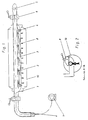
- Fig. 1 you can see a small in diameter compared to known substance distribution devices main pipe, here referred to as material feed pipe 1, which can be connected at its proximal curved end with a hose connection 6 for connection to a pump 7 matched to the flow resistance and the consumption of pressure substance .
- the substance feed tube extends over substantially the entire clear axial length of a screen printing cylinder 10 and is provided at its distal end with a locking pin 5 which is easily removable for internal cleaning.
- the main pipe or substance feed pipe 1 is connected over a substantial part of its axial length via a plurality of short connecting channels 2 to an additional pipe running parallel to it, here referred to as substance distributor pipe 3. Both ends of the substance distributor pipe 3 also open into the substance feed pipe 1 at an obtuse angle. These two openings can each be closed by a shut-off valve, preferably a ball valve 4.
- the substance distribution pipe 3 is thus, as is readily apparent to the person skilled in the art, connected in one piece to the substance supply pipe 1 both via the connecting channels 2 and via the two ends of the mouth.
- the substance distributor pipe 3 has a much smaller diameter than the substance feed pipe 1.
- the substance distributor pipe 3 Along an outer surface line facing away from the connecting channels 2, the substance distributor pipe 3 has a multiplicity of equally spaced substance distributor nozzles 8, the mutual axial spacing and diameter of which are dimensioned such that a substance application line is largely completely uniform and uniform material application or substance leakage is given.
- the substance distribution device also referred to here briefly as a “paint tube”, is held easily replaceable within the pressure cylinder 10 (see FIG. 2) by two clamping devices 9 (clamps).
- the new substance distribution device offers advantages, above all for users who want frequent and rapid color changes, with a particular ecological advantage being that a largely complete recovery of residual color can be ensured without any problems.
Landscapes
- Engineering & Computer Science (AREA)
- Mechanical Engineering (AREA)
- Screen Printers (AREA)
- Inking, Control Or Cleaning Of Printing Machines (AREA)
Applications Claiming Priority (2)
| Application Number | Priority Date | Filing Date | Title |
|---|---|---|---|
| DE1995138467 DE19538467C1 (de) | 1995-10-16 | 1995-10-16 | Farbverteilvorrichtung für eine Rotationssiebdruckmaschine |
| DE19538467 | 1995-10-16 |
Publications (1)
| Publication Number | Publication Date |
|---|---|
| EP0768175A1 true EP0768175A1 (fr) | 1997-04-16 |
Family
ID=7774972
Family Applications (1)
| Application Number | Title | Priority Date | Filing Date |
|---|---|---|---|
| EP96116174A Withdrawn EP0768175A1 (fr) | 1995-10-16 | 1996-10-09 | Dispositif de distribution d'encre pour une machine rotative de sérigraphie |
Country Status (2)
| Country | Link |
|---|---|
| EP (1) | EP0768175A1 (fr) |
| DE (1) | DE19538467C1 (fr) |
Cited By (2)
| Publication number | Priority date | Publication date | Assignee | Title |
|---|---|---|---|---|
| DE29921450U1 (de) * | 1999-12-08 | 2000-10-05 | Planatol Klebetechnik GmbH, 83101 Rohrdorf | Farbbalken für Farbkästen in Druckmaschinen |
| CN113415074A (zh) * | 2021-07-15 | 2021-09-21 | 呼和浩特市吉宏印刷包装有限公司 | 一种丝网上uv光油的圆压圆上光设备 |
Citations (4)
| Publication number | Priority date | Publication date | Assignee | Title |
|---|---|---|---|---|
| DE1029834B (de) * | 1956-01-05 | 1958-05-14 | Pelikan Werke Wagner Guenther | Farbzufuehrvorrichtung fuer Buerodruckmaschinen, insbesondere Rotationsschablonendrucker |
| DE2259225A1 (de) * | 1971-12-06 | 1973-06-20 | Peter Zimmer | Verfahren zum faerben oder bedrucken von warenbahnen |
| EP0056630A1 (fr) * | 1981-01-21 | 1982-07-28 | Kleinewefers, Jaeggli AG | Machine rotative de sérigraphie |
| DE3524127A1 (de) * | 1985-07-05 | 1987-01-08 | Guenter Butz | Auftragsvorrichtung bzw. schlitzrakel zum kontinuierlichen auftragen eines verschaeumten, pastoesen oder trockenen auftragsmediums |
Family Cites Families (5)
| Publication number | Priority date | Publication date | Assignee | Title |
|---|---|---|---|---|
| AT289157B (de) * | 1967-06-23 | 1971-04-13 | Peter Zimmer | Rakeleinrichtung für Siebdruckmaschinen |
| AT327144B (de) * | 1972-03-01 | 1976-01-12 | Zimmer Peter | Rakeleinrichtung |
| AT376612B (de) * | 1982-10-07 | 1984-12-10 | Johannes Zimmer | Einrichtung zum gleichmaessigen bzw. regelmaessigen verteilen fliessfaehiger medien in vorgegebener breite |
| DE9111789U1 (de) * | 1991-09-20 | 1991-11-14 | Wako Walzen Konstruktion Systembau GmbH, 4150 Krefeld | Vorrichtung zum kontinuierlichen Auftragen einer Flüssigkeit auf eine Materialbahn |
| DE9302207U1 (de) * | 1993-02-12 | 1994-06-09 | Zimmer, Johannes, Klagenfurt | Vorrichtung zum breitenverteilenden Auftragen fließfähiger Substanzen |
-
1995
- 1995-10-16 DE DE1995138467 patent/DE19538467C1/de not_active Expired - Lifetime
-
1996
- 1996-10-09 EP EP96116174A patent/EP0768175A1/fr not_active Withdrawn
Patent Citations (4)
| Publication number | Priority date | Publication date | Assignee | Title |
|---|---|---|---|---|
| DE1029834B (de) * | 1956-01-05 | 1958-05-14 | Pelikan Werke Wagner Guenther | Farbzufuehrvorrichtung fuer Buerodruckmaschinen, insbesondere Rotationsschablonendrucker |
| DE2259225A1 (de) * | 1971-12-06 | 1973-06-20 | Peter Zimmer | Verfahren zum faerben oder bedrucken von warenbahnen |
| EP0056630A1 (fr) * | 1981-01-21 | 1982-07-28 | Kleinewefers, Jaeggli AG | Machine rotative de sérigraphie |
| DE3524127A1 (de) * | 1985-07-05 | 1987-01-08 | Guenter Butz | Auftragsvorrichtung bzw. schlitzrakel zum kontinuierlichen auftragen eines verschaeumten, pastoesen oder trockenen auftragsmediums |
Cited By (2)
| Publication number | Priority date | Publication date | Assignee | Title |
|---|---|---|---|---|
| DE29921450U1 (de) * | 1999-12-08 | 2000-10-05 | Planatol Klebetechnik GmbH, 83101 Rohrdorf | Farbbalken für Farbkästen in Druckmaschinen |
| CN113415074A (zh) * | 2021-07-15 | 2021-09-21 | 呼和浩特市吉宏印刷包装有限公司 | 一种丝网上uv光油的圆压圆上光设备 |
Also Published As
| Publication number | Publication date |
|---|---|
| DE19538467C1 (de) | 1996-11-21 |
Similar Documents
| Publication | Publication Date | Title |
|---|---|---|
| DE69022051T2 (de) | Düse für zerstäubungsröhre. | |
| AT393246B (de) | Auftragsvorrichtung zum aufbringen fliessfaehiger medien auf ebene flaechen, bahnen, walzen od. dgl. | |
| EP0472050B1 (fr) | Dispositif pour l'application d'un film liquide sur une matière en bande | |
| DE2921554A1 (de) | Vorrichtung und verfahren zum aufbringen von fluessigkeit auf eine sich fortbewegende gutbahn | |
| EP0310826B1 (fr) | Installation permettant d'amener un liquide dans un réservoir allongé | |
| EP1122338B1 (fr) | Appareil pour projeter des liquides de décapage ou de rinçage sur des objets métalliques | |
| DE2419617A1 (de) | Vorrichtung zum behandeln von garnoder bandfoermigem material | |
| DE602005002888T2 (de) | Flexodruckmaschine mit Farbübertragungsvorrichtung | |
| DE19723802A1 (de) | Rohrelement und damit ausgerüstete Vorrichtung zum Auftragen eines fluiden Behandlungsmittels auf eine Bahn | |
| DE102013104921A1 (de) | Vorrichtung zum Beschichten und/oder Imprägnieren einer textilen Warenbahn | |
| DE19651576A1 (de) | Vorrichtung zum Aufbringen eines Flüssigkeitsfilmes auf eine kontinuierlich vorbewegte Warenbahn, Verfahren zur Herstellung eines Farbmusters auf einer Warenbahn und Muster hergestellt nach diesem Verfahren | |
| DE19538467C1 (de) | Farbverteilvorrichtung für eine Rotationssiebdruckmaschine | |
| DE2724888C3 (de) | Vorrichtung zur Reinigung von Tuscheschreiberspitzen | |
| EP0570763A1 (fr) | Dispositif de lavage pour machine à imprimer | |
| EP1867481A2 (fr) | Barre de pulvérisation pour liquide de nettoyage | |
| DE551246C (de) | Maschine zum mustermaessigen Faerben von Textilstoffbahnen mit Schablonen und Zerstaeubern | |
| EP3736236A1 (fr) | Tête d'épissure pour un dispositif d'épissure, dispositif d'épissure doté d'au moins une tête d'épissure, procédé d'épissure de fils au moyen d'une tête d'épissure, produit de programme informatique | |
| DE102017110774A1 (de) | Saugfuß für eine Bodenreinigungsmaschine | |
| DE102004022954B4 (de) | Bandreinigung und -behandlung | |
| EP0683700B1 (fr) | Procede et dispositif d'amenee d'une substance a un lieu d'application, ainsi que procede de nettoyage du dispositif | |
| DE29908005U1 (de) | Sprühvorrichtung, insbesondere für eine Druckmaschine | |
| EP1106728A1 (fr) | Procédé et dispositif pour le nettoyage local de surface textile | |
| DE575254C (de) | Brausenkopf fuer Streckspinnvorrichtungen | |
| DE102008042741B4 (de) | Reinigungsvorrichtung für einen Zylinder oder eine Walze einer Druckmaschine | |
| DE102005003030A1 (de) | Druckmaschinen-Befeuchtungsvorrichtung und Druckmaschinen-Waschvorrichtung |
Legal Events
| Date | Code | Title | Description |
|---|---|---|---|
| PUAI | Public reference made under article 153(3) epc to a published international application that has entered the european phase |
Free format text: ORIGINAL CODE: 0009012 |
|
| AK | Designated contracting states |
Kind code of ref document: A1 Designated state(s): AT CH DE IT LI NL |
|
| 17P | Request for examination filed |
Effective date: 19970324 |
|
| GRAG | Despatch of communication of intention to grant |
Free format text: ORIGINAL CODE: EPIDOS AGRA |
|
| GRAH | Despatch of communication of intention to grant a patent |
Free format text: ORIGINAL CODE: EPIDOS IGRA |
|
| 17Q | First examination report despatched |
Effective date: 19971125 |
|
| STAA | Information on the status of an ep patent application or granted ep patent |
Free format text: STATUS: THE APPLICATION HAS BEEN WITHDRAWN |
|
| 18W | Application withdrawn |
Withdrawal date: 19980709 |