EP0768193B1 - Système de détermination d'une réduction de la pression des pneumatiques d'un véhicule - Google Patents
Système de détermination d'une réduction de la pression des pneumatiques d'un véhicule Download PDFInfo
- Publication number
- EP0768193B1 EP0768193B1 EP96116334A EP96116334A EP0768193B1 EP 0768193 B1 EP0768193 B1 EP 0768193B1 EP 96116334 A EP96116334 A EP 96116334A EP 96116334 A EP96116334 A EP 96116334A EP 0768193 B1 EP0768193 B1 EP 0768193B1
- Authority
- EP
- European Patent Office
- Prior art keywords
- driven wheel
- wheels
- torque
- driven
- reduction
- Prior art date
- Legal status (The legal status is an assumption and is not a legal conclusion. Google has not performed a legal analysis and makes no representation as to the accuracy of the status listed.)
- Expired - Lifetime
Links
- 230000009467 reduction Effects 0.000 claims description 27
- 230000001133 acceleration Effects 0.000 description 6
- 238000010586 diagram Methods 0.000 description 4
- 238000012545 processing Methods 0.000 description 3
- 230000005540 biological transmission Effects 0.000 description 2
- 238000000034 method Methods 0.000 description 2
- 238000010420 art technique Methods 0.000 description 1
- 238000012986 modification Methods 0.000 description 1
- 230000004048 modification Effects 0.000 description 1
Images

Classifications
-
- B—PERFORMING OPERATIONS; TRANSPORTING
- B60—VEHICLES IN GENERAL
- B60C—VEHICLE TYRES; TYRE INFLATION; TYRE CHANGING; CONNECTING VALVES TO INFLATABLE ELASTIC BODIES IN GENERAL; DEVICES OR ARRANGEMENTS RELATED TO TYRES
- B60C23/00—Devices for measuring, signalling, controlling, or distributing tyre pressure or temperature, specially adapted for mounting on vehicles; Arrangement of tyre inflating devices on vehicles, e.g. of pumps or of tanks; Tyre cooling arrangements
- B60C23/06—Signalling devices actuated by deformation of the tyre, e.g. tyre mounted deformation sensors or indirect determination of tyre deformation based on wheel speed, wheel-centre to ground distance or inclination of wheel axle
- B60C23/061—Signalling devices actuated by deformation of the tyre, e.g. tyre mounted deformation sensors or indirect determination of tyre deformation based on wheel speed, wheel-centre to ground distance or inclination of wheel axle by monitoring wheel speed
Definitions
- the present invention relates to a tire pressure-reduction determining system for a vehicle for determining a reduction in pressure in a tire based on a difference in diameter between the tires fitted on the follower and driven wheels.
- a traction control system or an antilock brake system in a vehicle includes rotation-number sensors in the follower and driven wheels to detect follower wheel speeds and driven wheel speeds used for calculation of a slip rate of a wheel or the like.
- rotation-number sensors in the follower and driven wheels to detect follower wheel speeds and driven wheel speeds used for calculation of a slip rate of a wheel or the like.
- the above prior art technique suffers from the following problem: If the driven wheel is in a slipping state, the ratio of the number of rotations of the follower wheel to the number of rotations of the driven wheel cannot be correctly determined. Therefore, an error is generated in the difference in diameter between the follower and driven wheels, and the reduction in tire pressure cannot be accurately detected.
- the present invention addresses the afore-mentioned concerns, and it is an object of the present invention to provide a tire pressure-reduction determining system for a vehicle, wherein a reduction in pressure in the tires fitted to the follower wheels and the tires fitted to the driven wheels can be precisely determined irrespective of slipping states of the driven wheels.
- the invention provides a tire pressure-reduction determining system for wheels of a vehicle according to the subject-matter of claim 1.
- the system comprises : a driven wheel slip rate calculating means calculating driven wheel slip rates based on follower wheels speeds and driven wheel speeds; a driven wheel torque calculating means calculating a driven wheel torque based on an engine torque; a driven wheel slip rate estimating means estimating a characteristic variation in said driven wheel slip rates relative to the driven wheel torque based on the driven wheel slip rates and the driven wheel torque; and a tire pressure-reduction determining means determining a reduction in pressure of tires fitted to said driven wheels based on said variation characteristic estimated by said driven wheel slip rate estimating means, characterized in that a rotation-number ratio calculating means is provided which calculates rotation-number ratios between follower wheels and driven wheels as the driven wheel slip rates at the time when the driven wheel torque is zero, from said variation characteristic estimated by said driven wheel slip rate estimating means; and that said tire pressure-reduction determining means is capable of determining a
- a reduction in pressure in one of the tires fitted to the left and right follower wheels and one of the tires fitted to the left and right driven wheels is determined by calculating a rotation-number ratio between one of the left and right follower wheels and one of the left and right driven wheels based on one of the left and right follower wheels speeds and one of the driven wheel speeds.
- the driven wheel slip rate estimating means obtains data for estimating the variation characteristic of the driven wheel slip rates relative to the driven wheel torque in each of a plurality of torque areas classified depending upon the magnitude of the driven wheel torque, and obtains data in the torque area including a state of the driven wheel torque of zero in an amount greater than the amount of data in the other torque areas.
- a driven wheel torque area limiting means for limiting the torque area inputs data for estimating the variation characteristic by the driven wheel slip rate estimating means, in accordance with the friction coefficient of a road surface.
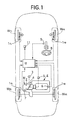
- Fig. 1 is a diagrammatic illustration of a vehicle including tire pressure-reduction determining system of the present invention.
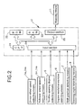
- Fig. 2 is a block diagram of a control system.
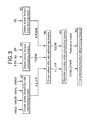
- Fig. 3 is a block diagram of the tire pressure-reduction determining system.
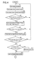
- Fig. 4 is a first portion of a flow chart for determining the tire pressure-reduction.
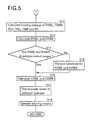
- Fig. 5 is a second portion of the flow chart for determining the tire pressure-reduction.
- Fig. 6 is a graph illustrating the characteristic of variation in slip rate of driven wheels.
- Figs. 1 to 6 illustrate a preferred embodiment of the present invention, where Fig. 1 is a diagrammatic illustration of a vehicle including a wheel pressure-reduction determining system, Fig. 2 is a block diagram of a control system, Fig. 3 is a block diagram of the tire pressure-reduction determining system, Fig. 4 is a first portion of a flow chart for determining the tire pressure-reduction, Fig. 5 is a second portion of the flow chart for determining the tire pressure-reduction, and Fig. 6 is a graph illustrating the characteristic of variation in slip rate of driven wheels.
- the vehicle is a rear-wheel drive vehicle and includes a pair of left and right driven wheels W RL and W RR driven by an engine E, and a pair of steerable follower wheels W FL and W FR .
- Driven wheel speed detecting means 1 RL and 1 RR are mounted on the driven wheels W RL and W RR
- follower wheel speed detecting means 1 FL and 1 FR are mounted on the follower wheels W FL and W FR .
- a throttle valve 4 is mounted in an intake passage 2 in the engine E and connected to and opened and closed by a pulse motor 3.
- the opening degree ⁇ TH of the throttle valve 4 is detected by a throttle opening degree detecting means 5.
- An engine revolution-number detecting means 6 is mounted in the engine E for detecting a number Ne of revolutions of the engine E, and a shift position detecting means 7 is mounted in a transmission M for detecting a shift position SP. Further, a steering angle detecting means 9 is mounted on a steering wheel 8 for detecting steering angle ⁇ .
- the driven wheel speed detecting means 1 RL and 1 RR , the follower wheel speed detecting means 1 FL and 1 FR , the throttle opening degree detecting means 5, the engine revolution-number detecting means 6, the shift position detecting means 7 and the steering angle detecting means 9 are connected to an electronic control unit U including a microcomputer. Further, a warning means 11 such as a lamp, a buzzer, chime or the like is connected to the electronic control unit U to give a warning when a difference in diameter is generated between tires fitted to the wheels due to a reduction in tire pressure.
- Fig. 2 shows the electronic control unit U which calculates signals from the various detecting means according to a control program to operate the warning means 11 in order to give a warning when the reduction in pressure in the tire is generated.
- the electronic control unit U includes a central processing unit (CPU) 21 for carrying out the calculations, a read-only memory (ROM) 22 having the control program and data such as various maps and the like stored therein, a random access memory (RAM) 23 for temporarily storing the output signals from the various detecting means and the calculation means, an input section 24 to which the various detecting means, i.e., the driven wheel speed detecting means 1 RL and 1 RR , the follower wheel speed detecting means 1 FL and 1 FR , the throttle opening degree detecting means 6, the shift position detecting means 7 and the steering angle detecting means are connected, and an output section 25 to which the warning means 11 is connected.
- the electronic control unit U calculates the various signals inputted through the input section and the data stored in the read-only memory 22 in the central processing unit 21 according to
- the tire pressure-reduction determining system includes a driven wheel slip rate calculating means M1, a driven wheel torque calculating means M2, a driven wheel torque area limiting means M3, a driven wheel slip rate estimating means M4, a rotation-number ration calculating means M5, and a tire pressure-reduction determining means M6.
- the driven wheel slip rate calculating means M1 calculates slip rates ⁇ L and ⁇ R of the left and right driven wheels based on driven wheel speeds VWDL and VWDR detected by the driven wheel speed detecting means 1 RL and 1 RR and follower wheel speeds VWNL and VWNR detected by the follower wheel speed detecting means 1 FL and 1 FR .
- the driven wheel torque calculating means M2 calculates a driven wheel torque TQDW based on the throttle opening degree ⁇ TH detected by the throttle opening degree detecting means 5, the engine revolution-number Ne detected by the engine revolution-number detecting means 6 and the shift position SP detected by the shift position detecting means 7.
- the driven wheel torque area limiting means M3 calculates a driven wheel limit torque KTQDW depending upon the friction coefficient of a road surface based on a longitudinal acceleration FG of the vehicle.
- the driven wheel slip rate estimating means M4 presumes a characteristic of variation in driven wheel slip rates ⁇ L and ⁇ R relative to the driven wheel torque TQDW, based on the driven wheel slip rates ⁇ L and ⁇ R, the driven wheel torque TQDW and the driven wheel limit torque KTQDW.
- the rotation-number ratio calculating means M5 calculates rotation-number ratios CVWL and CVWR between the follower wheels W FL and W FR and the driven wheels W RL and W RR , based on the characteristic of variation in driven wheel slip rates ⁇ L and ⁇ R relative to the driven wheel torque TQDW.
- the tire pressure-reduction determining means M6 determines reductions in pressure in the tires fitted to the follower wheels W FL and W FR and the tires fitted to the driven wheels W RL and W RR by comparing the rotation-number ratios CVWL and CVWR between the follower wheels W FL and W FR and the driven wheels W RL and W RR with a predetermined reference value.
- an engine torque is calculated from the opening degree ⁇ TH of the throttle valve 4 detected by the throttle opening degree detecting means 5 and the engine revolution-number Ne detected by the engine revolution-number detecting means 6, and a driven wheel torque TQDW is calculated by multiplying a primary filtered value of the engine torque by a gear ratio in the shift position SP detected by the shift position detecting means 7 (at step S2).
- the driven wheel torque TQDW may assume a negative value, for example, during operation of an engine brake.
- the driven wheel limit torque KTQDW is a value which varies depending upon the friction coefficient ⁇ of the road surface. The value is smaller on a road surface having a lower friction coefficient ⁇ and larger on a road surface having a higher friction coefficient ⁇ .
- the driven wheel slip rate estimating means M4 it is determined whether stability conditions for carrying out the determination of the reduction in pressure of the wheel have been established (at step S5). More specifically, it is determined whether any of the four wheel speeds VWDL, VWDR, VWNL and VWNR are in predetermined ranges; whether the amounts of variation in driven wheel speeds VWDL and VWDR and in follower wheel speeds VWNL and VWNR within a predetermined time are in predetermined ranges; whether the longitudinal acceleration and the lateral acceleration are in predetermined ranges; whether the number Ne of revolutions of the engine is in a predetermined range; whether the driven wheel torque TQDW is in a predetermined range; whether the variation rate of the steering angle ⁇ is in a predetermined range; whether the vehicle is not being braked; whether the vehicle is not being subjected to a traction control; whether the transmission is not being shift-changed; whether the travelling of the vehicle is not on a bad road; whether the difference between the left and right driven wheel speeds VWDL and VWDR and the difference between the left and right follower
- the driven wheel torque TQDW and the left and right driven wheel slip rates ⁇ L and ⁇ R calculated in every loop are added in sequence until a lapse of a stable time (a time for which an n-loop is carried out) according to the following equations (1) to (6) to calculate six addition values TVWL, TVWR, TCV, TWL, TWR and TC (at steps S5 and S6):
- TVWL (n) TQDW (1) x ⁇ L (1) + TQDW (2) x ⁇ L (2) + ... + TQDW(n) x ⁇ L(n)
- TVWR (n) TQDW (1) x ⁇ R (1) + TQDW (2) x ⁇ R (2) + ...
- TQDW(n) x ⁇ R(n) TCV (n) TQDW (1) 2 + TQDW (2) 2 + ... + TQDW (n) 2
- TWL (n) ⁇ L (1) + ⁇ L (2) + ... + ⁇ L (n)
- TWR (n) ⁇ R (1) + ⁇ R (2) + ...+ ⁇ R (n)
- TC (n) TQDW (1) + TQDW (2) + ... + TQDW (n)
- the addition value TC of the driven wheel torque TQDW calculated according to the equation (6) is divided by n to calculate an average value of the driven wheel torques (at step S7).
- the average value of the driven wheel torques TQDW calculated at step S7 is compared with the driven wheel limit torque KTQDW calculated at step S3. If the average value of the driven wheel torques TQDW does not exceed the driven wheel limit torque KTQDW, i.e., when the torque area is an area in which a linearity is maintained in the relationship between the driven wheel torque and the driven wheel slip rate, the processings at step S10 and subsequent steps are carried out (at step S8).
- the characteristic of variation in driven wheel slip rates ⁇ L and ⁇ R relative to the variation in driven wheel torque TQDW which will be described hereinafter.
- the average value of the driven wheel torques TQDW is classified into, for example, eight torque areas (1), (2), (3), (4), (5), (6), (7) and (8).
- the area (1) is a minimum torque area (a negative value); the area (8) is a maximum torque are (a positive value); and the area (3) is a zero-torque area (a torque area in which the driven wheel torque is near zero).
- the eight torque areas (1) to (8) are established in correspondence to the left driven wheel W RL and W RL , respectively.
- Corresponding counters are provided in the eight torque areas (1) to (8), respectively.
- the moving average of the four addition values TVWL, TVWR, TCV TWL, TWR and TC is calculated for each of the eight torque areas (1) to (8).
- the value of the counter in each of the torque areas (1) to (8) assumed 1 which is the maximum value at that time, the calculation of the six addition values TVWL, TVWR, TCV TWL, TWR and TC and the moving average of them in each of the torque areas (1) to (8) is discontinued.
- a gradient KVWL is calculated from an equation (8) based on the moving average of the four addition values TVWL, TCV, TWL and TC, and a gradient KVWR is calculated from an equation (9) based on the moving average of the four addition values TVWL, TCV, TWR and TC (at step S13).
- KVWL ⁇ n x TVWL - TWL x TC ⁇ / ⁇ n x TCV - TC 2 ⁇
- KVWR ⁇ n x TVWR - TWR x TC ⁇ / ⁇ n x TCV - TC 2 ⁇
- the gradient KVWL obtained from the equation (6) corresponds to a gradient when the driven wheel torque TQDW in the characteristic curve of the left front and rear wheels W FL and W RL is equal to 0 (zero)
- the gradient KVWR obtained from the equation (9) corresponds to a gradient when the driven wheel torque TQDW in the characteristic curve of the right front and rear wheels W FR and W RR is equal to 0 (zero).
- the intercept CVWL represents a ratio of the number of rotations of the left follower wheel W FL to the number of rotations of the left driven wheel W RL when the left driven wheel W RL is not in a slipping state
- the intercept CVWR represents a ratio of the number of rotations of the right follower wheel W FR to the number of rotations of the right driven wheel W RR when the right driven wheel W RR is not in a slipping state.
- a difference between the intercept CVWL and a stored referenced value determined by learning, or a difference between the intercept CVWL and a previously set reference value is calculated. If such difference is greater than predetermined threshold value, it is determined that a reduction in diameter due to a reduction in the pressure has been produced in the left driven wheel W RL or the left follower wheel W FL (at step S17), and the warning means 11 is operated to give a warning to a driver (at step S18). At this time, it can be determined which of the left driven wheel W RL or the left follower wheel W FL has been reduced in diameter, based on the magnitude of the relationship between the intercept CVWL and the reference value.
- a difference between the intercept CVWR and a reference value is calculated. If such difference is greater than a predetermined threshold value, it is determined that a reduction in diameter has been produced in the right driven wheel W RR or the right follower wheel W FR , and the warning means 11 is operated (at steps S17 and S18). At this time, it can be determined which of the right driven wheel W RR or the right follower wheel W FR has been reduced in diameter, based on the magnitude of the relationship between the intercept CVWR and the reference value.
- the driven wheel slip rates ⁇ L and ⁇ R at the time when the driven wheel torque is extremely small are estimated, and the ratios CVWL and CVWR of the numbers of rotations of the follower wheels W FL and W RR to the numbers of rotations of the driven wheels W FL and W RR are calculated based on the driven wheel slip rates ⁇ L and ⁇ R. Therefore, a reduction in pressure of the tires fitted to the follower wheels W FL and W FR and the tires fitted to the driven wheels W RL and W RR can be accurately determined while eliminating an influence of the slips of the driven wheels W RL and W RR .
- the ratio CVWL of the number of rotations of the left follower wheels W FL to the number of rotations of the left driven wheels W RL and the ratio CVWR of the number of rotations of the right follower wheels W FR to the number of rotations of the right driven wheels W RR are individually calculated. Therefore, it is possible not only to determine the reduction in diameter of the follower wheels W FL and W FR or the reduction in diameter of the driven wheel W RL and W RR , but also to accurately determine which of the left and right follower wheels W FL and W FR has been reduced in diameter, or which of the left and right driven wheels W RL and W RR has been reduced in diameter.
- the ratio CVWL of the number of rotations of the left follower wheels W FL to the number of rotations of the left driven wheels W RL and the ratio CVWR of the number of rotations of the right follower wheels W FR to the number of rotations of the right driven wheels W RR are individually calculated in the embodiment.
- the ratios CVWL and CVWR of the numbers of rotations of the follower wheels W FL and W FR to the numbers of rotations of the driven wheels W RL and W RR may be calculated using an average value of the left and right follower wheel speeds VWNL and VWNR as a follower wheel speed and using an average value of the left and right driven wheel speeds VWDL and VWDR.
- the reduction in wheel diameter cannot be determined in a wheelspecifying manner, but it can be determined that a reduction in diameter has been produced in the follower wheels W FL and W FR , or that a reduction in diameter has been produced in the driven wheels W RL and W RR .
- a reduction in pressure in tires fitted to follower wheels and driven wheels is precisely determined irrespective of slipping states of the driven wheels.
- a driven wheel slip rate calculating means M1 calculates driven wheel slip rates ⁇ L and ⁇ R.
- a driven wheel torque calculating means M2 calculates a driven wheel torque TQDW.
- a driven wheel slip rate estimating means M4 estimates a characteristic of variation in driven wheel slip rates ⁇ L and ⁇ R relative to the variation in driven wheel torque TQDW using a least squares method.
- a rotation-number ratio calculating means M5 calculates ratios CVWL and CVWR of the numbers of rotations of the follower wheels to the numbers of rotations of the driven wheels in a state in which the driven wheel torque in a graph of the variation characteristic is equal to zero.
- a tire pressure-reduction determining means M6 determines a reduction in pressure from a difference in diameter between the follower wheels and the driven wheels by comparing the rotation-number ratios CVWL and CVWR with a reference value.
Landscapes
- Engineering & Computer Science (AREA)
- Mechanical Engineering (AREA)
- Regulating Braking Force (AREA)
- Control Of Driving Devices And Active Controlling Of Vehicle (AREA)
- Control Of Vehicle Engines Or Engines For Specific Uses (AREA)
Claims (4)
- Système pour déterminer une réduction de pression de pneumatique destiné aux roues d'un véhicule, comprenant :caractérisé en ce qu'un moyen de calcul de rapport de nombre de tours (M5) sont prévus, lesquels calculent les rapports de nombre de tours (CVWL et CVWR) entre les roues subordonnées (WFL et WFR) et les roues menées (WRL et WRR) comme les degrés de patinage de roue menée (λL et λR) au moment où le couple de roue menée (TQDW) est nul, à partir de ladite caractéristique de variation estimée par ledit moyen d'estimation de degré de patinage de roue menée (M4) ; etun moyen de calcul de degré de patinage de roue menée (M1) calculant des degrés de patinage de roue menée (λL et λR) en se basant sur des vitesses de roue subordonnée (VWNL et VWNR) et sur des vitesses de roue menée (VWDL et VWDR) ;un moyen de calcul de couple de roue menée (M2) calculant un couple de roue menée (TQDW) en se basant sur un couple moteur ;un moyen d'estimation de degré de patinage de roue menée (M4) estimant une variation caractéristique desdits degrés de patinage de roue menée (λL et λR) par rapport au couple de roue menée (TQDW) en se basant sur les degrés de patinage de roue menée (λL et λR) et sur le couple de roue menée (TQDW) ; etun moyen de détermination de réduction de pression de pneumatique déterminant une réduction de pression de pneumatiques montés sur lesdites roues menées (WRL et WRR) en se basant sur ladite caractéristique de variation estimée par ledit moyen d'estimation de degré de patinage de roue menée (M4),
en ce que ledit moyen de détermination de réduction de pression de pneumatique est apte à déterminer une réduction de pression de pneumatiques montés sur les roues subordonnées (WFL et WFR), en plus des pneumatiques montés sur les roues menées (WRL et WRR) en comparant les rapports de nombre de tours (CVWL et CVWR) calculés par lesdits moyens de calcul de rapport de nombre de tours (M5) avec une valeur de référence prédéterminée. - Système pour déterminer une réduction de pression de pneumatique destiné aux roues d'un véhicule selon la revendication 1, dans lequel une réduction de pression dans un des pneumatiques montés sur les roues subordonnées gauche et droite (WFL et WFR) et dans un des pneumatiques montés sur les roues menées gauche et droite (WRL et WRR) est déterminée en calculant un rapport de nombre de tours (CVWL et CVWR) entre l'une des roues subordonnées gauche et droite (WFL et WFR) et l'une des roues menées gauche et droite (WRL et WRR) en se basant sur l'une des vitesses des roues subordonnées gauche et droite (VWNL et VWNR) et sur l'une des vitesses des roues menées (VWDL et VWDR).
- Système pour déterminer une réduction de pression de pneumatique destiné aux roues d'un véhicule selon la revendication 1, dans lequel ledit moyen d'estimation de degré de patinage de roue menée (M4) obtient des données d'estimation de ladite caractéristique de variation des degrés de patinage de roue menée (λL et λR) par rapport au couple de roue menée (TQDW) dans chacune d'une pluralité de zones de couple classées en fonction de l'amplitude du couple de roue menée (TQDW), et obtiennent des données dans les zones de couple comprenant un état dans lequel le couple de roue menée est nul dans une quantité supérieure à la quantité de données dans les autres zones de couple.
- Système pour déterminer une réduction de pression de pneumatique destiné aux roues d'un véhicule selon la revendication 1, comprenant en outre un moyen limitant la zone de couple de roue menée (M3) afin de limiter la zone de couple qui introduit des données pour estimer ladite caractéristique de variation à l'aide dudit moyen d'estimation de degré de patinage de roue menée (M4) selon le coefficient de frottement de la surface d'une route.
Applications Claiming Priority (3)
| Application Number | Priority Date | Filing Date | Title |
|---|---|---|---|
| JP262684/95 | 1995-10-11 | ||
| JP26268495 | 1995-10-11 | ||
| JP26268495A JP3509330B2 (ja) | 1995-10-11 | 1995-10-11 | 車両の車輪減圧判定装置 |
Publications (2)
| Publication Number | Publication Date |
|---|---|
| EP0768193A1 EP0768193A1 (fr) | 1997-04-16 |
| EP0768193B1 true EP0768193B1 (fr) | 2001-08-01 |
Family
ID=17379160
Family Applications (1)
| Application Number | Title | Priority Date | Filing Date |
|---|---|---|---|
| EP96116334A Expired - Lifetime EP0768193B1 (fr) | 1995-10-11 | 1996-10-11 | Système de détermination d'une réduction de la pression des pneumatiques d'un véhicule |
Country Status (4)
| Country | Link |
|---|---|
| US (1) | US5747686A (fr) |
| EP (1) | EP0768193B1 (fr) |
| JP (1) | JP3509330B2 (fr) |
| DE (1) | DE69614216T2 (fr) |
Cited By (1)
| Publication number | Priority date | Publication date | Assignee | Title |
|---|---|---|---|---|
| CN104709002A (zh) * | 2013-12-13 | 2015-06-17 | 北汽福田汽车股份有限公司 | 胎压报警方法、胎压报警装置和车辆 |
Families Citing this family (27)
| Publication number | Priority date | Publication date | Assignee | Title |
|---|---|---|---|---|
| US5839801A (en) * | 1997-04-04 | 1998-11-24 | Itt Manufacturing Enterprises, Inc. | Variable tire pressure traction control enhancement |
| US6137400A (en) * | 1997-08-22 | 2000-10-24 | Sumitomo Rubber Industries, Ltd. | Apparatus and method for detecting decrease in tire air-pressure |
| JP3340961B2 (ja) * | 1997-10-06 | 2002-11-05 | 住友ゴム工業株式会社 | タイヤ空気圧低下警報装置および方法 |
| DE19807880A1 (de) * | 1998-02-25 | 1999-09-09 | Daimler Chrysler Ag | Verfahren und Vorrichtung zur Überwachung des Reifenluftdrucks von Rädern eines Kraftfahrzeuges |
| DE10024178A1 (de) * | 2000-05-17 | 2001-12-06 | Wabco Gmbh & Co Ohg | Verfahren zur verbesserten Bestimmung des Verhältnisses der Radien der Räder eines Fahrzeuges zueinander |
| US6285280B1 (en) | 2000-06-26 | 2001-09-04 | Robert Bosch Corporation | Method for detecting a deflated tire on a vehicle |
| DE10129737B4 (de) * | 2000-10-18 | 2015-04-02 | Continental Teves Ag & Co. Ohg | Verfahren und Vorrichtung zur Erkennung eines Reifendruckverlusts in Abhängigkeit von Fahrdynamikgrößen |
| US6459369B1 (en) | 2000-11-22 | 2002-10-01 | Robert Bosch Corporation | Tire deflation detection system with feedback component |
| CN1491166A (zh) | 2001-02-08 | 2004-04-21 | ��ʽ�����װ | 基于车速信号检测气压的轮胎气压检测装置 |
| JP3869685B2 (ja) | 2001-06-20 | 2007-01-17 | 住友ゴム工業株式会社 | 二輪車用空気圧低下検出装置および方法、ならびに二輪車用減圧判定プログラム |
| WO2003016115A1 (fr) * | 2001-07-30 | 2003-02-27 | Continental Teves Ag & Co. Ohg | Procede destine a determiner la charge imposee a un pneumatique de vehicule |
| JP2003267012A (ja) * | 2002-01-09 | 2003-09-25 | Sumitomo Rubber Ind Ltd | タイヤ空気圧低下検出方法および装置、ならびにタイヤ減圧判定のプログラム |
| JP3923808B2 (ja) * | 2002-01-23 | 2007-06-06 | 住友ゴム工業株式会社 | タイヤ空気圧低下警報方法および装置、ならびにタイヤ減圧判定のプログラム |
| EP1487649A1 (fr) * | 2002-03-16 | 2004-12-22 | Robert Bosch Gmbh | Systeme de surveillance de l'etat d'un pneumatique |
| JP3834261B2 (ja) * | 2002-05-10 | 2006-10-18 | 住友ゴム工業株式会社 | タイヤ空気圧低下検出方法および装置、ならびにタイヤ減圧判定のプログラム |
| JP2004203214A (ja) * | 2002-12-25 | 2004-07-22 | Sumitomo Rubber Ind Ltd | タイヤ空気圧低下検出方法および装置、ならびにタイヤ減圧判定のプログラム |
| US20040191923A1 (en) * | 2003-03-31 | 2004-09-30 | Tomasso David Angelo | Test element holder with a probe guide for an analyzer |
| JP4028842B2 (ja) * | 2003-12-25 | 2007-12-26 | 住友ゴム工業株式会社 | タイヤ空気圧低下検出方法および装置、ならびにタイヤ減圧判定のプログラム |
| CN101448660B (zh) | 2006-05-31 | 2010-12-01 | 住友橡胶工业株式会社 | 轮胎气压下降警报方法 |
| FR2933033B1 (fr) * | 2008-06-30 | 2010-08-20 | Renault Sas | Procede et dispositif de detection de perte de pression dans les pneumatiques |
| JP4742158B2 (ja) * | 2008-11-26 | 2011-08-10 | 住友ゴム工業株式会社 | タイヤ空気圧低下検出装置及び方法、並びにタイヤの空気圧低下検出プログラム |
| DE102012023463B4 (de) * | 2012-11-30 | 2023-03-23 | Volkswagen Aktiengesellschaft | Verfahren und Erkennungssystem zur Erkennung eines Luftdruckabfalls in mindestens einem Fahrzeugreifen, sowie ein Fahrzeug mit einem derartigen Erkennungssystem |
| JP6337528B2 (ja) | 2014-03-10 | 2018-06-06 | 村田機械株式会社 | 走行車輪の劣化検出方法と検出システム、及び走行台車 |
| KR101566748B1 (ko) * | 2014-06-02 | 2015-11-06 | 현대자동차 주식회사 | 모터 구동 차량의 타이어 압력 모니터링 시스템 및 이를 이용한 타이어 압력 모니터링 방법 |
| TR201517733A2 (tr) | 2015-12-31 | 2017-07-21 | Mehmet Selcuk Arslan | Taşitlarda lasti̇k basinci i̇çi̇n bi̇r öneri̇ si̇stemi̇ |
| JP7103010B2 (ja) * | 2018-07-19 | 2022-07-20 | 住友ゴム工業株式会社 | 路面状態の判定装置、方法及びプログラム |
| CN110978911B (zh) * | 2019-12-20 | 2021-09-14 | 福建农林大学 | 一种汽车胎压监测装置及应用其监测系统 |
Family Cites Families (6)
| Publication number | Priority date | Publication date | Assignee | Title |
|---|---|---|---|---|
| DE4102769C2 (de) * | 1991-01-31 | 1995-11-09 | Telefunken Microelectron | Verfahren zur Luftdruckkontrolle von Kraftfahrzeugreifen |
| US5327346A (en) * | 1991-08-23 | 1994-07-05 | Harsco Corporation | Automatic control for central tire inflation system |
| JP2780887B2 (ja) * | 1992-01-31 | 1998-07-30 | 本田技研工業株式会社 | 車両のタイヤ空気圧判定装置 |
| DE4327492C1 (de) * | 1993-08-16 | 1995-02-16 | Daimler Benz Ag | Verfahren zur Reifendruckwarnung |
| JP2746338B2 (ja) * | 1993-09-30 | 1998-05-06 | 本田技研工業株式会社 | タイヤ空気圧判定装置 |
| DE4400913B4 (de) * | 1994-01-14 | 2004-09-09 | Continental Aktiengesellschaft | Verfahren und Vorrichtung zur Ermittlung eines Fülldruckverlusts in einem Reifen |
-
1995
- 1995-10-11 JP JP26268495A patent/JP3509330B2/ja not_active Expired - Fee Related
-
1996
- 1996-10-09 US US08/729,235 patent/US5747686A/en not_active Expired - Fee Related
- 1996-10-11 EP EP96116334A patent/EP0768193B1/fr not_active Expired - Lifetime
- 1996-10-11 DE DE69614216T patent/DE69614216T2/de not_active Expired - Fee Related
Cited By (2)
| Publication number | Priority date | Publication date | Assignee | Title |
|---|---|---|---|---|
| CN104709002A (zh) * | 2013-12-13 | 2015-06-17 | 北汽福田汽车股份有限公司 | 胎压报警方法、胎压报警装置和车辆 |
| CN104709002B (zh) * | 2013-12-13 | 2017-02-15 | 北汽福田汽车股份有限公司 | 胎压报警方法、胎压报警装置和车辆 |
Also Published As
| Publication number | Publication date |
|---|---|
| JP3509330B2 (ja) | 2004-03-22 |
| JPH09104209A (ja) | 1997-04-22 |
| EP0768193A1 (fr) | 1997-04-16 |
| DE69614216D1 (de) | 2001-09-06 |
| DE69614216T2 (de) | 2001-11-15 |
| US5747686A (en) | 1998-05-05 |
Similar Documents
| Publication | Publication Date | Title |
|---|---|---|
| EP0768193B1 (fr) | Système de détermination d'une réduction de la pression des pneumatiques d'un véhicule | |
| EP0773118B1 (fr) | Système de détermination d'une réduction de la pression des pneumatiques d'un véhicule | |
| US6456920B1 (en) | Apparatus for estimating a vehicle side slip angle | |
| JP3334647B2 (ja) | 車両のヨーレイト検出装置 | |
| US6473682B2 (en) | Apparatus and method for estimating maximum road friction coefficient | |
| US5370199A (en) | Vehicle traction control system | |
| US6015192A (en) | System for estimating vehicle body speed and road surface friction coefficient | |
| US5828975A (en) | Method and device for calculating turning radius of vehicle taking load movement thereof into consideration | |
| US6564140B2 (en) | Vehicle dynamics control system and vehicle having the vehicle dynamics control system | |
| US6904351B1 (en) | Operating a vehicle control system | |
| US20020032512A1 (en) | Vehicle drive force control system and method | |
| JP3607985B2 (ja) | 車輌の車体速度推定装置及び制御装置 | |
| US7058541B2 (en) | Device for a vehicle for estimating friction coefficient of a road surface | |
| US6427130B1 (en) | Method and device for regulating a quantity of motion representing the movement of a vehicle | |
| US5725067A (en) | Wheel speed correcting system | |
| US20030141128A1 (en) | Method and system for controlling and/or regulating the handling characteristics of a motor vehicle | |
| US6266599B1 (en) | Method and device for adjusting an amount of movement representing the vehicle motion | |
| US5771479A (en) | Wheel diameter difference judging system and wheel speed correcting system | |
| EP1332895B1 (fr) | Appareil et procédé concernant la détection d'une baisse de pression dans un pneumatique | |
| JP3236391B2 (ja) | 4輪駆動車の車体速度算出方法 | |
| US5329805A (en) | Vehicle body speed estimating method in anti-lock control system for vehicle | |
| US20050029862A1 (en) | Vehicle motion control apparatus | |
| JPH0986367A (ja) | 車輌の車体速度推定装置及び車輪の自由回転速度推定装置 | |
| US5652383A (en) | Longitudinal grip force estimating device and slip control device for vehicle | |
| JP3290457B2 (ja) | 車両の車体速度検出装置 |
Legal Events
| Date | Code | Title | Description |
|---|---|---|---|
| PUAI | Public reference made under article 153(3) epc to a published international application that has entered the european phase |
Free format text: ORIGINAL CODE: 0009012 |
|
| AK | Designated contracting states |
Kind code of ref document: A1 Designated state(s): DE GB |
|
| 17P | Request for examination filed |
Effective date: 19970425 |
|
| 17Q | First examination report despatched |
Effective date: 19991014 |
|
| GRAG | Despatch of communication of intention to grant |
Free format text: ORIGINAL CODE: EPIDOS AGRA |
|
| GRAG | Despatch of communication of intention to grant |
Free format text: ORIGINAL CODE: EPIDOS AGRA |
|
| GRAH | Despatch of communication of intention to grant a patent |
Free format text: ORIGINAL CODE: EPIDOS IGRA |
|
| GRAH | Despatch of communication of intention to grant a patent |
Free format text: ORIGINAL CODE: EPIDOS IGRA |
|
| GRAA | (expected) grant |
Free format text: ORIGINAL CODE: 0009210 |
|
| AK | Designated contracting states |
Kind code of ref document: B1 Designated state(s): DE GB |
|
| REF | Corresponds to: |
Ref document number: 69614216 Country of ref document: DE Date of ref document: 20010906 |
|
| REG | Reference to a national code |
Ref country code: GB Ref legal event code: IF02 |
|
| PLBE | No opposition filed within time limit |
Free format text: ORIGINAL CODE: 0009261 |
|
| STAA | Information on the status of an ep patent application or granted ep patent |
Free format text: STATUS: NO OPPOSITION FILED WITHIN TIME LIMIT |
|
| 26N | No opposition filed | ||
| PGFP | Annual fee paid to national office [announced via postgrant information from national office to epo] |
Ref country code: GB Payment date: 20041006 Year of fee payment: 9 |
|
| PGFP | Annual fee paid to national office [announced via postgrant information from national office to epo] |
Ref country code: DE Payment date: 20041007 Year of fee payment: 9 |
|
| PG25 | Lapsed in a contracting state [announced via postgrant information from national office to epo] |
Ref country code: GB Free format text: LAPSE BECAUSE OF NON-PAYMENT OF DUE FEES Effective date: 20051011 |
|
| PG25 | Lapsed in a contracting state [announced via postgrant information from national office to epo] |
Ref country code: DE Free format text: LAPSE BECAUSE OF NON-PAYMENT OF DUE FEES Effective date: 20060503 |
|
| GBPC | Gb: european patent ceased through non-payment of renewal fee |
Effective date: 20051011 |