EP0768224B1 - Dispositif d'actionnement pour un système de freinage à commande électronique d'un véhicule à moteur - Google Patents
Dispositif d'actionnement pour un système de freinage à commande électronique d'un véhicule à moteur Download PDFInfo
- Publication number
- EP0768224B1 EP0768224B1 EP95307220A EP95307220A EP0768224B1 EP 0768224 B1 EP0768224 B1 EP 0768224B1 EP 95307220 A EP95307220 A EP 95307220A EP 95307220 A EP95307220 A EP 95307220A EP 0768224 B1 EP0768224 B1 EP 0768224B1
- Authority
- EP
- European Patent Office
- Prior art keywords
- piston
- actuation
- cylinder
- brake system
- brake pedal
- Prior art date
- Legal status (The legal status is an assumption and is not a legal conclusion. Google has not performed a legal analysis and makes no representation as to the accuracy of the status listed.)
- Expired - Lifetime
Links
- 239000012530 fluid Substances 0.000 claims description 10
- 230000001133 acceleration Effects 0.000 claims description 6
- 230000006835 compression Effects 0.000 description 2
- 238000007906 compression Methods 0.000 description 2
- 238000010276 construction Methods 0.000 description 2
- 230000001419 dependent effect Effects 0.000 description 1
- 238000006073 displacement reaction Methods 0.000 description 1
- 230000007257 malfunction Effects 0.000 description 1
- 230000000750 progressive effect Effects 0.000 description 1
- 238000007789 sealing Methods 0.000 description 1
Images

Classifications
-
- B—PERFORMING OPERATIONS; TRANSPORTING
- B60—VEHICLES IN GENERAL
- B60T—VEHICLE BRAKE CONTROL SYSTEMS OR PARTS THEREOF; BRAKE CONTROL SYSTEMS OR PARTS THEREOF, IN GENERAL; ARRANGEMENT OF BRAKING ELEMENTS ON VEHICLES IN GENERAL; PORTABLE DEVICES FOR PREVENTING UNWANTED MOVEMENT OF VEHICLES; VEHICLE MODIFICATIONS TO FACILITATE COOLING OF BRAKES
- B60T13/00—Transmitting braking action from initiating means to ultimate brake actuator with power assistance or drive; Brake systems incorporating such transmitting means, e.g. air-pressure brake systems
- B60T13/10—Transmitting braking action from initiating means to ultimate brake actuator with power assistance or drive; Brake systems incorporating such transmitting means, e.g. air-pressure brake systems with fluid assistance, drive, or release
- B60T13/66—Electrical control in fluid-pressure brake systems
- B60T13/68—Electrical control in fluid-pressure brake systems by electrically-controlled valves
- B60T13/686—Electrical control in fluid-pressure brake systems by electrically-controlled valves in hydraulic systems or parts thereof
-
- B—PERFORMING OPERATIONS; TRANSPORTING
- B60—VEHICLES IN GENERAL
- B60T—VEHICLE BRAKE CONTROL SYSTEMS OR PARTS THEREOF; BRAKE CONTROL SYSTEMS OR PARTS THEREOF, IN GENERAL; ARRANGEMENT OF BRAKING ELEMENTS ON VEHICLES IN GENERAL; PORTABLE DEVICES FOR PREVENTING UNWANTED MOVEMENT OF VEHICLES; VEHICLE MODIFICATIONS TO FACILITATE COOLING OF BRAKES
- B60T11/00—Transmitting braking action from initiating means to ultimate brake actuator without power assistance or drive or where such assistance or drive is irrelevant
- B60T11/10—Transmitting braking action from initiating means to ultimate brake actuator without power assistance or drive or where such assistance or drive is irrelevant transmitting by fluid means, e.g. hydraulic
- B60T11/16—Master control, e.g. master cylinders
-
- B—PERFORMING OPERATIONS; TRANSPORTING
- B60—VEHICLES IN GENERAL
- B60T—VEHICLE BRAKE CONTROL SYSTEMS OR PARTS THEREOF; BRAKE CONTROL SYSTEMS OR PARTS THEREOF, IN GENERAL; ARRANGEMENT OF BRAKING ELEMENTS ON VEHICLES IN GENERAL; PORTABLE DEVICES FOR PREVENTING UNWANTED MOVEMENT OF VEHICLES; VEHICLE MODIFICATIONS TO FACILITATE COOLING OF BRAKES
- B60T13/00—Transmitting braking action from initiating means to ultimate brake actuator with power assistance or drive; Brake systems incorporating such transmitting means, e.g. air-pressure brake systems
- B60T13/10—Transmitting braking action from initiating means to ultimate brake actuator with power assistance or drive; Brake systems incorporating such transmitting means, e.g. air-pressure brake systems with fluid assistance, drive, or release
- B60T13/66—Electrical control in fluid-pressure brake systems
-
- B—PERFORMING OPERATIONS; TRANSPORTING
- B60—VEHICLES IN GENERAL
- B60T—VEHICLE BRAKE CONTROL SYSTEMS OR PARTS THEREOF; BRAKE CONTROL SYSTEMS OR PARTS THEREOF, IN GENERAL; ARRANGEMENT OF BRAKING ELEMENTS ON VEHICLES IN GENERAL; PORTABLE DEVICES FOR PREVENTING UNWANTED MOVEMENT OF VEHICLES; VEHICLE MODIFICATIONS TO FACILITATE COOLING OF BRAKES
- B60T7/00—Brake-action initiating means
- B60T7/02—Brake-action initiating means for personal initiation
- B60T7/04—Brake-action initiating means for personal initiation foot actuated
- B60T7/042—Brake-action initiating means for personal initiation foot actuated by electrical means, e.g. using travel or force sensors
-
- B—PERFORMING OPERATIONS; TRANSPORTING
- B60—VEHICLES IN GENERAL
- B60T—VEHICLE BRAKE CONTROL SYSTEMS OR PARTS THEREOF; BRAKE CONTROL SYSTEMS OR PARTS THEREOF, IN GENERAL; ARRANGEMENT OF BRAKING ELEMENTS ON VEHICLES IN GENERAL; PORTABLE DEVICES FOR PREVENTING UNWANTED MOVEMENT OF VEHICLES; VEHICLE MODIFICATIONS TO FACILITATE COOLING OF BRAKES
- B60T8/00—Arrangements for adjusting wheel-braking force to meet varying vehicular or ground-surface conditions, e.g. limiting or varying distribution of braking force
- B60T8/32—Arrangements for adjusting wheel-braking force to meet varying vehicular or ground-surface conditions, e.g. limiting or varying distribution of braking force responsive to a speed condition, e.g. acceleration or deceleration
- B60T8/34—Arrangements for adjusting wheel-braking force to meet varying vehicular or ground-surface conditions, e.g. limiting or varying distribution of braking force responsive to a speed condition, e.g. acceleration or deceleration having a fluid pressure regulator responsive to a speed condition
- B60T8/40—Arrangements for adjusting wheel-braking force to meet varying vehicular or ground-surface conditions, e.g. limiting or varying distribution of braking force responsive to a speed condition, e.g. acceleration or deceleration having a fluid pressure regulator responsive to a speed condition comprising an additional fluid circuit including fluid pressurising means for modifying the pressure of the braking fluid, e.g. including wheel driven pumps for detecting a speed condition, or pumps which are controlled by means independent of the braking system
- B60T8/4072—Systems in which a driver input signal is used as a control signal for the additional fluid circuit which is normally used for braking
- B60T8/4081—Systems with stroke simulating devices for driver input
-
- B—PERFORMING OPERATIONS; TRANSPORTING
- B60—VEHICLES IN GENERAL
- B60T—VEHICLE BRAKE CONTROL SYSTEMS OR PARTS THEREOF; BRAKE CONTROL SYSTEMS OR PARTS THEREOF, IN GENERAL; ARRANGEMENT OF BRAKING ELEMENTS ON VEHICLES IN GENERAL; PORTABLE DEVICES FOR PREVENTING UNWANTED MOVEMENT OF VEHICLES; VEHICLE MODIFICATIONS TO FACILITATE COOLING OF BRAKES
- B60T8/00—Arrangements for adjusting wheel-braking force to meet varying vehicular or ground-surface conditions, e.g. limiting or varying distribution of braking force
- B60T8/32—Arrangements for adjusting wheel-braking force to meet varying vehicular or ground-surface conditions, e.g. limiting or varying distribution of braking force responsive to a speed condition, e.g. acceleration or deceleration
- B60T8/34—Arrangements for adjusting wheel-braking force to meet varying vehicular or ground-surface conditions, e.g. limiting or varying distribution of braking force responsive to a speed condition, e.g. acceleration or deceleration having a fluid pressure regulator responsive to a speed condition
- B60T8/40—Arrangements for adjusting wheel-braking force to meet varying vehicular or ground-surface conditions, e.g. limiting or varying distribution of braking force responsive to a speed condition, e.g. acceleration or deceleration having a fluid pressure regulator responsive to a speed condition comprising an additional fluid circuit including fluid pressurising means for modifying the pressure of the braking fluid, e.g. including wheel driven pumps for detecting a speed condition, or pumps which are controlled by means independent of the braking system
- B60T8/4072—Systems in which a driver input signal is used as a control signal for the additional fluid circuit which is normally used for braking
- B60T8/4081—Systems with stroke simulating devices for driver input
- B60T8/4086—Systems with stroke simulating devices for driver input the stroke simulating device being connected to, or integrated in the driver input device
-
- B—PERFORMING OPERATIONS; TRANSPORTING
- B60—VEHICLES IN GENERAL
- B60T—VEHICLE BRAKE CONTROL SYSTEMS OR PARTS THEREOF; BRAKE CONTROL SYSTEMS OR PARTS THEREOF, IN GENERAL; ARRANGEMENT OF BRAKING ELEMENTS ON VEHICLES IN GENERAL; PORTABLE DEVICES FOR PREVENTING UNWANTED MOVEMENT OF VEHICLES; VEHICLE MODIFICATIONS TO FACILITATE COOLING OF BRAKES
- B60T8/00—Arrangements for adjusting wheel-braking force to meet varying vehicular or ground-surface conditions, e.g. limiting or varying distribution of braking force
- B60T8/32—Arrangements for adjusting wheel-braking force to meet varying vehicular or ground-surface conditions, e.g. limiting or varying distribution of braking force responsive to a speed condition, e.g. acceleration or deceleration
- B60T8/34—Arrangements for adjusting wheel-braking force to meet varying vehicular or ground-surface conditions, e.g. limiting or varying distribution of braking force responsive to a speed condition, e.g. acceleration or deceleration having a fluid pressure regulator responsive to a speed condition
- B60T8/40—Arrangements for adjusting wheel-braking force to meet varying vehicular or ground-surface conditions, e.g. limiting or varying distribution of braking force responsive to a speed condition, e.g. acceleration or deceleration having a fluid pressure regulator responsive to a speed condition comprising an additional fluid circuit including fluid pressurising means for modifying the pressure of the braking fluid, e.g. including wheel driven pumps for detecting a speed condition, or pumps which are controlled by means independent of the braking system
- B60T8/4072—Systems in which a driver input signal is used as a control signal for the additional fluid circuit which is normally used for braking
- B60T8/4081—Systems with stroke simulating devices for driver input
- B60T8/409—Systems with stroke simulating devices for driver input characterised by details of the stroke simulating device
Definitions
- the present invention relates to an actuation means suitable for use in an electronically controlled brake system of a motor vehicle, according to the preamble of claim 1.
- Brake cylinder means of differing designs are well known in the art.
- brake by wire systems the actuation of the brake pedal by a driver is sensed electronically by a sensor means coupled to the brake pedal.
- the signal derived from said sensor means is fed into an electronic control unit (ECU).
- ECU electronice control unit
- the input signal is processed and an electronical output signal is provided to activate an electromechanical actuator which operates on brake pads at the wheels.
- This parallel path is from the brake pedal means via a fluid brake cylinder to an hydraulic actuator operating the brake pads at the wheels in case the brake by wire path fails.
- Such a system is called a "push-through-system".
- the hydraulic piston is inoperative.
- the signal from the sensor means is ignored or not present, the brake pedal is "pushing-through” the brake cylinder and feeds hydraulic fluid to the brake pads at the vehicle wheels in order to decelerate the vehicle.
- DE 43 43 314 A1 discloses a "Brake-By-Wire" brake system for motor vehicles, with an electric motor driving a pump for supplying hydraulic fluid under high pressure, and a piston sliding in a chamber of a housing.
- the chamber is optionally connected to brake circuits of the brake system during an emergency actuation.
- the piston is connected to a brake pedal.
- a pedal feeling simulator is provided, including a spring resiliently biasing the brake pedal.
- Two sensors one sensing the pedal angle, the other sensing the pressure in the chamber of the piston, supply signals concerning the state of the system. The signals are compared in a control unit to identify an emergency situation.
- the spring of the pedal feeling simulator is connected to the brake pedal and mounted within the housing in parallel to the piston.
- DE 23 27 508 A1 discloses a break actuation device, having an emergency break piston for feeding hydraulic fluid into hydraulic circuits of a break system.
- the piston is actuated by an actuation rod of a break pedal.
- a signal generator is connected with the break actuation device for generating a signal representative for the degree of break pedal actuation.
- the signal generator is located between the actuation rod and the piston, outside of the break actuation device and comprises a spring.
- By actuating the break pedal the actuation rod is moved and the spring is compressed.
- the applied force is related to the amount of compression.
- the signal generator works as a force sensor.
- the force signal is compared with an acceleration signal of the vehicle acceleration and the brakes are controlled accordingly.
- DE 22 49 007 A1 which shows all the features of the preamble of claim 1, discloses an emergency break piston actuated by an actuation rod of a break pedal and a signal generator located between the actuation rod and the piston, outside of the break actuation device.
- the signal generator comprises a spring for generating a signal representative for the degree of force applied to the break pedal.
- DE 22 49 007 A1 further describes a pressure sensor and a comparator.
- the coparator triggers switching operations of hydraulic valves.
- the construction of the sensors is not relevant for the control principle of this disclosure. Thus, the principle of this prior art is to control the pressure in the hydraulic circuits related to the degree of force applied at the break pedal.
- the pressure sensor can also be used for detecting leakage in the hydraulic circuits.
- JP-042 32 154 A a force and a stroke sensor at a brake operation member are disclosed.
- the two sensors are used as redundant system for detecting whether one of them failed.
- the spring means is responsible for the "pedal feeling" for a driver. If the spring means is inoperative, the brake pedal can not be used in a satisfactory manner. Moreover, during an absence of a properly working spring means the brake pedal might be actuated once but will not be returned to its rest position. Therefore, it would be impossible to safely drive the motor vehicle.
- One object underlying the present invention is to provide an actuation means suitable for use in an electronically controlled brake system which is simple and reliable.
- the prior art actuation means includes at least a force sensor, a pressure sensor and an acceleration sensor for sensing these dimension related to an actuation of the brake pedal.
- the sensor adapted for sensing a force representative for an actuation force acting on the brake pedal allows for a very accurate and direct sensing of the actuation of the brake pedal means by a driver.
- a pressure sensor is influenced by all kinds of pressure variation within the hydraulic circuits.
- An acceleration sensor is influenced by the inertia of the vehicle.
- prior art sensor combinations are not sufficient for checking functionality and operability of the spring means.
- break actuation devices as described in DE 23 27 508 A1 and DE 22 49 007 A1
- a rupture of the spring would cause a situation of serious danger, as the brake pedal could move without any force being applied to it.
- the movement would be detected by the displacement sensor of the force sensor, the signal would be interpreted as a brake demand by the driver and this would lead to a brake actuation.
- Such an undefined brake actuation could lead to uncontrolled performance and could cause accidents.
- the actuation means according to the invention is characterized in that the member is a second piston of the cylinder/piston means not for feeding hydraulic fluid into the brake system of the motor vehicle, in that the second piston and the spring means being located within the cylinder/piston means, and in that a second of the sensor means is sensing the distance between a predetermined location on said brake pedal and a location being in a fixed relation to a support means of said brake pedal, or resulting from a movement of the second piston relative to the cylinder of said cylinder/piston means.
- a force sensor and a linear detector allows for sensing physical dimensions and values that are suitable for recognising any malfunction of the actuation means and especially of the spring means resiliently biasing the brake pedal against an actuation direction of the brake pedal.
- the distance measured by the linear detector is inconsistent with the force acting on the stepping plate sensed by the force sensor.
- a third of said sensor means is adapted for sensing a pressure representative for a pressure in a chamber of the cylinder/piston means delimited by the first piston. Since this pressure may be sensed in the brake system also to check other situations, there are usually no additional costs involved.
- the spring means is mounted coaxially to the first and second piston of said cylinder/piston means and/or said actuation rod.
- a support means for supporting the cylinder of the cylinder/piston means relative to the brake pedal means is rigidly mounted to the cylinder of the cylinder/piston means.
- the present invention also relates to an electronically controlled brake system of a motor vehicle having an actuation means as described above, wherein a valve means is mounted intermediate said cylinder/piston means and the brake system of the motor vehicle to separate a chamber of the cylinder/piston means delimited by the first piston from the brake system during a normal actuation and to connect the chamber of the cylinder/piston means with the brake system for an emergency actuation.
- said electronic control unit is adapted to put sensor signals representing a dimension resulting from an actuation of the brake pedal into a relation with a speed, acceleration and/or traction signal resulting from the rotational behaviour of the wheels of said motor vehicle.
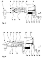
- a prior art actuation means for an electronically controlled brake system of a motor vehicle comprises a cylinder/piston means 10 formed of a hydraulic cylinder 12 and a hydraulic piston 14 axially movable within said cylinder 12.
- the piston 14 is biased into its rest position by a helical spring means 16 abutting the bottom 18 of the cylinder 12 and the front face 22 of the piston 14.
- the piston 14 is provided with a hollow cylindrical tube 24 at the side opposite the front face 22. In this tube 24 one end portion of a pushing rod 26 is slidably mounted. The other end portion of the pushing rod 26 is rotatably connected to a brake pedal 28 by a fulcrum 30.
- the brake pedal 28 is provided with a stepping plate 32 at the free end thereof and is rotatably supported at the other end of the brake pedal 22 by a supporting pin 34.
- a first sensor means 36 is coupled to the brake pedal 28 or the pin 34 to sense a rotational movement of the brake pedal 28 about the pin 34 relative to a support 38 of the brake pedal 28.
- a spring means 40 is provided coaxially to the actuation rod 26 and the hollow cylindrical tube 24 intermediate the brake pedal 28 and the piston 14 of the cylinder/piston means 10.
- a second sensor means 42 is provided in a fluid conduit 44 connecting a hydraulic chamber 46 in the cylinder/piston means 10 with an electromagnetic valve 48.
- the second sensor means 42 is a pressure sensor adapted for sensing the pressure in the chamber 46 defined by the cylinder 10 and the piston 14 of the cylinder/piston means 10 and/or in the conduit 44.
- the electromagnetic valve means 48 In the normal actuation position, the electromagnetic valve means 48 is in its closed position. Consequently, the volume of the hydraulic chamber 46 can not be changed by actuating the brake pedal 28. However, the pressure in the hydraulic chamber 46 is increased as the spring means 40 pushes the piston 14 in the direction P upon depression of the brake pedal 28. This is sensed by the second sensor means 42 sensing the pressure in the chamber 46. At the same time, the rotational angle ⁇ of the brake pedal 28 about the pin 34 is sensed with the first sensor means 36. The output signals of the two sensor means 36, 42 are fed into an electronic control unit ECU (not shown). Within the electronic control unit, these two sensor signals are processed and among other operations checked for consistency.
- ECU electronice control unit
- the valve means 48 is an electromagnetic valve having two positions, the first position where an inlet port 48a of the valve means 48 is separated from an outlet port 48b and a second position where the inlet port 48a is in fluid connection with the outlet port 48b.
- an electromagnetic means 48c the electromagnetic valve means 48 is forced into the first position against the force of a spring means 48d.
- the spring means 48d forces the valve 48 into the second position.
- the first position where the chamber 46 of the cylinder/piston means 10 is separated from the brake system is the normal actuation position, whereas the second position is the emergency actuation position, where the hydraulic fluid from the chamber 46 is fed into the brake system via the valve means 48 upon an actuation of the brake pedal 28.
- the signal from the first sensor means 36 representing the rotational angle of the brake pedal 28 with respect to the pin 34 is inconsistent with the signal from the second sensor means 42 detecting the pressure in the hydraulic chamber 46.
- the spring means 40 is surrounding the actuation rod 26. Consequently, the cylinder/piston means 10 can be designed as a encapsulated unit independently from the type of motor vehicle in which the actuation means is to be used. The spring means can be selected as desired and mounted in the actuation means without the necessity of changing the design and construction of the cylinder/piston means 10.
- the main difference between the prior art embodiment of fig. 1 and the prior art embodiment of fig. 2 is the type of sensor used to replace the rotational angle sensor 36 in fig. 1.
- a sensor adapted for sensing the distances between a predetermined location along the brake pedal 28 and the support means 32, namely a linear detector 54 is provided.
- a part from that, the structure and mode of operation as well as the advantages obtained thereby are the same as with the prior-art embodiment of fig. 1.
- the spring means 40 being mounted within the cylinder/piston means 10.
- the piston 14 is comprised of two parts 14a and 14b.
- the first part 14a is sealing the chamber 46.
- the second part 14b is rigidly connected with the actuation rod 26 and is held separated from the first part 14a by the spring means 40 in the rest position (shown in fig. 3).
- the travel path of the brake pedal 28 is sensed with the linear detector 54 between the support 38 and the brake pedal 28.
- the force acting on the stepping plate 32 is sensed by a force sensor 56 mounted in the stepping plate 32. If a rupture of the spring 40 occurs, the distance measured by the linear detector 54 is inconsistent with the force acting on the stepping plate 32 sensed by the force sensor 56.
- the main difference between the first embodiment of the invention of fig. 3 and the second embodiment of the invention of fig. 4 is the sensing of the movement of the actuation rod 26 or the second part 14b of the piston 14 which are rigidly connected to each other relative to the support means 38 of the brake pedal 28 or the cylinder 12 of the cylinder/piston means 10 which are also rigidly coupled to each other.
- the signal provided by the force sensor 56 representing the force acted on the stepping plate 32 is inconsistent with the signal provided by the linear detector 54 representing the relative movement between the actuation rod and the second part of the piston 14b relative to the cylinder 12 or the support means 38.
- the force sensor means 56 mounted intermediate the piston 14 and the spring means 40 surrounding the actuation rod 26.
- the spring means 40 may be more than one spring element or several spring elements.
- the spring means 40 can have a non-linear, preferably progressive, spring characteristic in order to give the driver the same or similar pedal feeling as with an conventional brake system during a normal actuation.
- An inconsistency between the signal derived from the force sensor 56 and the sensor signal from the distance sensor means provided in the actuation means can be detected by an electronic control unit ECU and indicates the failure of a component in the actuation means.
Landscapes
- Engineering & Computer Science (AREA)
- Transportation (AREA)
- Mechanical Engineering (AREA)
- Physics & Mathematics (AREA)
- Fluid Mechanics (AREA)
- Braking Systems And Boosters (AREA)
- Regulating Braking Force (AREA)
- Braking Elements And Transmission Devices (AREA)
- Braking Arrangements (AREA)
Claims (6)
- Moyen d'actionnement convenant pour une utilisation dans un système de freinage à commande électronique d'un véhicule à moteur, comprenantun moyen cylindre/piston (10) ayant un premier piston (14a) pour amener un fluide hydraulique à un système de freinage d'un véhicule à moteur,un élément (14b) n'amenant pas de fluide hydraulique dans le système de freinage du véhicule à moteur, étant connecté à une tige d'actionnement (26) et étant maintenu séparé dudit premier piston (14a) par un moyen à ressort (40) monté entre ledit élément et ledit premier piston,ladite tige d'actionnement (26) étant montée entre une pédale de frein (28) et ledit élément (14b) et étant alignée avec ledit premier piston (14a),ledit moyen à ressort (40) poussant de manière élastique la pédale de frein (28) contre la direction d'actionnement (P) de cette pédale de frein (28),au moins deux capteurs (36, 42, 54, 56) pour détecter des dimensions relatives à un actionnement normal de la pédale de frein (28), lesdits au moins deux capteurs (36, 42, 54, 56) émettant des signaux de détection vers une unité de commande électronique où ils sont traités et vérifiés,un premier capteur (56) parmi les capteurs détectant une force (F) représentant une force d'actionnement agissant sur ladite pédale de frein (28),
caractérisé en ce queledit élément (14b) est un second piston du moyen cylindre/piston (10) n'amenant pas de fluide hydraulique au système de freinage du véhicule à moteur,en ce que ledit second piston (14b) et ledit moyen à ressort (40) sont situés à l'intérieur du moyen cylindre/piston (10), et en ce queun second capteur (54) parmi lesdits capteurs détecte la distance (S), entre un lieu prédéterminé sur ladite pédale de frein (28) et un lieu en relation fixe avec un moyen de support (38) de ladite pédale de frein (28), résultant d'un mouvement du second piston (14b) par rapport au cylindre (12) dudit moyen cylindre/piston (10). - Moyen d'actionnement convenant pour une utilisation dans un système de freinage à commande électronique selon la revendication 1, caractérisée en ce queun troisième capteur (42) parmi les capteurs est conçu pour détecter une pression (P) représentative de la pression dans une chambre (46) du moyen cylindre/piston (10) délimitée par ledit premier piston (14a).
- Moyen d'actionnement convenant pour une utilisation dans un système de freinage à commande électronique selon l'une quelconque des revendications 1 ou 2, caractérisé en ce queledit moyen à ressort (40) est monté de manière coaxiale auxdits premier et second pistons (14a, 14b) et/ou à ladite tige d'actionnement (26).
- Moyen d'actionnement convenant pour une utilisation dans un système de freinage à commande électronique selon l'une quelconque des revendications 1 ou 3, caractérisé en ce que ledit moyen de support (38) est coupé rigidement audit cylindre (12) du moyen cylindre/piston (10).
- Système de freinage à commande électronique d'un véhicule à moteur comprenant un moyen d'actionnement selon l'une quelconque des revendications 1 à 4, caractérisé en ce queune soupape (48) est montée entre ledit moyen cylindre/piston (10) et le système de freinage du véhicule à moteur pour séparer une chambre (46) du moyen cylindre/piston (10), délimitée par ledit premier piston (14a), du système de freinage pendant un actionnement normal et pour connecter ladite chambre (46) au système de freinage pour un actionnement d'urgence.
- Système de freinage à commande électronique d'un véhicule à moteur comprenant un moyen d'actionnement selon l'une quelconque des revendications 1 à 4, caractérisé en ce queladite unité de commande électronique (ECU) est adaptée pour mettre les signaux de détection représentant une dimension résultant de l'actionnement de la pédale de frein (28) en relation avec une vitesse, une accélération et/ou signal de traction résultant du comportement rotatif des roues dudit véhicule à moteur.
Priority Applications (4)
| Application Number | Priority Date | Filing Date | Title |
|---|---|---|---|
| DE69514360T DE69514360T2 (de) | 1995-10-11 | 1995-10-11 | Betätigungseinrichtung für ein elektronisch gesteuertes Bremssystem eines Kraftfahrzeuges |
| EP95307220A EP0768224B1 (fr) | 1995-10-11 | 1995-10-11 | Dispositif d'actionnement pour un système de freinage à commande électronique d'un véhicule à moteur |
| ES95307220T ES2139847T3 (es) | 1995-10-11 | 1995-10-11 | Medio de accionamiento para sistema de freno controlado electronicamente de un vehiculo a motor. |
| KR1019960044056A KR970021824A (ko) | 1995-10-11 | 1996-10-05 | 자동차용 브레이크 실린더 수단 |
Applications Claiming Priority (1)
| Application Number | Priority Date | Filing Date | Title |
|---|---|---|---|
| EP95307220A EP0768224B1 (fr) | 1995-10-11 | 1995-10-11 | Dispositif d'actionnement pour un système de freinage à commande électronique d'un véhicule à moteur |
Publications (2)
| Publication Number | Publication Date |
|---|---|
| EP0768224A1 EP0768224A1 (fr) | 1997-04-16 |
| EP0768224B1 true EP0768224B1 (fr) | 2000-01-05 |
Family
ID=8221358
Family Applications (1)
| Application Number | Title | Priority Date | Filing Date |
|---|---|---|---|
| EP95307220A Expired - Lifetime EP0768224B1 (fr) | 1995-10-11 | 1995-10-11 | Dispositif d'actionnement pour un système de freinage à commande électronique d'un véhicule à moteur |
Country Status (4)
| Country | Link |
|---|---|
| EP (1) | EP0768224B1 (fr) |
| KR (1) | KR970021824A (fr) |
| DE (1) | DE69514360T2 (fr) |
| ES (1) | ES2139847T3 (fr) |
Cited By (1)
| Publication number | Priority date | Publication date | Assignee | Title |
|---|---|---|---|---|
| CN102123894B (zh) * | 2008-08-19 | 2014-10-15 | 罗伯特.博世有限公司 | 用于测量车辆制动设备的操纵力的连接元件 |
Families Citing this family (23)
| Publication number | Priority date | Publication date | Assignee | Title |
|---|---|---|---|---|
| DE59801376D1 (de) | 1997-04-16 | 2001-10-11 | Siemens Ag | Bremswertgeber für eine elektrisch gesteuerte und betätigte bremsanlage |
| AU8279598A (en) * | 1997-06-30 | 1999-01-19 | Kelsey-Hayes Company | Braking system with remote boost valve |
| WO1999039950A1 (fr) * | 1998-02-07 | 1999-08-12 | Continental Teves Ag & Co. Ohg | Procede et dispositif pour la commande ou la regulation du systeme de freinage d'un vehicule selon le principe du frein par cable |
| DE19836690A1 (de) * | 1998-08-13 | 2000-02-17 | Continental Teves Ag & Co Ohg | Pedaleinheit für eine elektromechanische Bremsanlage |
| JP4399947B2 (ja) * | 2000-03-30 | 2010-01-20 | 株式会社アドヴィックス | 車両用液圧ブレーキシステムの制御方法 |
| FR2813841B1 (fr) * | 2000-09-14 | 2002-10-25 | Renault | Systeme et procede d'analyse de freinage d'un vehicule |
| DE10137602B4 (de) * | 2001-08-01 | 2004-08-26 | Hella Kg Hueck & Co. | Elektrisches Bremssystem |
| JP2005075162A (ja) * | 2003-09-01 | 2005-03-24 | Matsushita Electric Ind Co Ltd | ブレーキシステム |
| JP4313219B2 (ja) | 2004-02-09 | 2009-08-12 | 豊田鉄工株式会社 | ペダル反力装置 |
| JP4313233B2 (ja) | 2004-03-19 | 2009-08-12 | 豊田鉄工株式会社 | 車両用ブレーキ装置 |
| JP4313243B2 (ja) | 2004-04-26 | 2009-08-12 | 豊田鉄工株式会社 | 車両用電気式操作装置 |
| US8180545B2 (en) | 2009-04-29 | 2012-05-15 | GM Global Technology Operations LLC | Methods and systems for calibrating braking systems and controlling braking in vehicles |
| DE102010034671A1 (de) * | 2010-08-18 | 2012-02-23 | Volkswagen Ag | Fahrzeugbremsanlage mit Pedalsimulator |
| DE102011016125A1 (de) | 2011-04-05 | 2012-10-11 | Lucas Automotive Gmbh | Technik zum redundanten Erfassen einer Betätigung einer Kraftfahrzeug-Bremsanlage |
| DE102011016241A1 (de) * | 2011-04-06 | 2012-10-11 | Volkswagen Ag | Pedalkraftsimulator für eine Fahrzeugbremse mit elektronischer Signalübertragung |
| US10059322B2 (en) * | 2015-10-23 | 2018-08-28 | Tse Brakes, Inc. | Apparatuses, systems, and methods for detecting air brake spring failure on a vehicle |
| CN106515686B (zh) * | 2016-12-05 | 2019-05-28 | 潍柴动力股份有限公司 | 制动踏板控制器、制动踏板信号处理方法及制动踏板 |
| WO2018123530A1 (fr) * | 2016-12-26 | 2018-07-05 | 日立オートモティブシステムズ株式会社 | Suramplificateur électrique |
| AU2020314797A1 (en) * | 2019-07-15 | 2022-02-03 | Jay Leroy THOMSON | Motorcycle braking arrangement |
| DE102019121245A1 (de) * | 2019-08-06 | 2021-02-11 | HELLA GmbH & Co. KGaA | Bremspedal für ein Fahrzeug, Kraftsensor und Verfahren zum Betrieb eines Bremspedals |
| DE102021119443A1 (de) * | 2021-07-27 | 2023-02-02 | Zf Active Safety Gmbh | Bremspedalmodul |
| DE102021119446A1 (de) | 2021-07-27 | 2023-02-02 | Zf Active Safety Gmbh | Bremspedalmodul |
| CN114397110B (zh) * | 2021-12-15 | 2023-07-07 | 重庆长安汽车股份有限公司 | 一种汽车制动系统耐久性测试装置及方法 |
Citations (2)
| Publication number | Priority date | Publication date | Assignee | Title |
|---|---|---|---|---|
| US3690737A (en) * | 1970-12-07 | 1972-09-12 | Gen Motors Corp | Anti-lock brake system |
| WO1995029830A1 (fr) * | 1994-05-03 | 1995-11-09 | Itt Automotive Europe Gmbh | Systeme d'actionnement de frein regulable electroniquement |
Family Cites Families (10)
| Publication number | Priority date | Publication date | Assignee | Title |
|---|---|---|---|---|
| DE2249007A1 (de) * | 1972-10-06 | 1974-04-18 | Teldix Gmbh | Fahrzeugbremsanlage mit antiblockierschutz |
| DE2327508A1 (de) * | 1973-05-30 | 1974-12-19 | Teldix Gmbh | Fahrzeugbremsanlage |
| DE2531264C2 (de) * | 1975-07-12 | 1986-10-02 | Robert Bosch Gmbh, 7000 Stuttgart | Hauptbremszylinder für Zweikreisbremsanlagen |
| DE3236582A1 (de) * | 1982-10-02 | 1984-04-05 | Robert Bosch Gmbh, 7000 Stuttgart | Hydraulischer bremsdruckerzeuger |
| JP2590825B2 (ja) * | 1986-07-12 | 1997-03-12 | トヨタ自動車株式会社 | マニユアル・電気二系統ブレーキ装置 |
| JPH04232154A (ja) * | 1990-12-28 | 1992-08-20 | Toyota Motor Corp | ブレーキ装置のセンサフェール検出方法 |
| DE4102497C1 (fr) * | 1991-01-29 | 1992-05-07 | Mercedes-Benz Aktiengesellschaft, 7000 Stuttgart, De | |
| JP3191245B2 (ja) * | 1992-02-28 | 2001-07-23 | アイシン精機株式会社 | 制動力制御装置 |
| DE4343314A1 (de) * | 1993-12-18 | 1995-06-22 | Bosch Gmbh Robert | Fremdkraftbremsanlage |
| DE4343386B4 (de) * | 1993-12-18 | 2004-04-22 | Robert Bosch Gmbh | Hydraulische Bremsanlage für Straßenfahrzeuge, insbesondere Personenkraftwagen |
-
1995
- 1995-10-11 ES ES95307220T patent/ES2139847T3/es not_active Expired - Lifetime
- 1995-10-11 DE DE69514360T patent/DE69514360T2/de not_active Expired - Fee Related
- 1995-10-11 EP EP95307220A patent/EP0768224B1/fr not_active Expired - Lifetime
-
1996
- 1996-10-05 KR KR1019960044056A patent/KR970021824A/ko not_active Withdrawn
Patent Citations (2)
| Publication number | Priority date | Publication date | Assignee | Title |
|---|---|---|---|---|
| US3690737A (en) * | 1970-12-07 | 1972-09-12 | Gen Motors Corp | Anti-lock brake system |
| WO1995029830A1 (fr) * | 1994-05-03 | 1995-11-09 | Itt Automotive Europe Gmbh | Systeme d'actionnement de frein regulable electroniquement |
Cited By (1)
| Publication number | Priority date | Publication date | Assignee | Title |
|---|---|---|---|---|
| CN102123894B (zh) * | 2008-08-19 | 2014-10-15 | 罗伯特.博世有限公司 | 用于测量车辆制动设备的操纵力的连接元件 |
Also Published As
| Publication number | Publication date |
|---|---|
| ES2139847T3 (es) | 2000-02-16 |
| EP0768224A1 (fr) | 1997-04-16 |
| DE69514360D1 (de) | 2000-02-10 |
| DE69514360T2 (de) | 2000-09-28 |
| KR970021824A (ko) | 1997-05-28 |
Similar Documents
| Publication | Publication Date | Title |
|---|---|---|
| EP0768224B1 (fr) | Dispositif d'actionnement pour un système de freinage à commande électronique d'un véhicule à moteur | |
| KR101804337B1 (ko) | 특히 차량 브레이크 시스템을 위한 작동 장치 | |
| US6253635B1 (en) | Brake pedal configuration | |
| US8985714B2 (en) | Break actuating unit for actuating a motor vehicle brake system | |
| US6354671B1 (en) | Brake signal transmitter with integrated addition redundancy | |
| US6347518B1 (en) | Pedal simulator using spring with non-linear response | |
| EP0708006B1 (fr) | Ensemble de pédale pour systèmes de freinage pour véhicules | |
| KR101578392B1 (ko) | 브레이크 작동 유닛 | |
| US5567021A (en) | Power-assisted brake system | |
| EP1577184B1 (fr) | Appareil de freinage d'un véhicule | |
| KR0169720B1 (ko) | 모우터 차량용 제동장치 | |
| US4655511A (en) | Hydraulic brake booster with travel simulator and associated anti-skid brake system | |
| US6471304B1 (en) | Brake value signal transmitter for an electrically controlled and activated brake system | |
| JP2002511361A (ja) | ブレーキ圧力制御装置 | |
| US4799570A (en) | Arrangement in vehicle hydraulic service brake systems | |
| JP2581739B2 (ja) | アンチロックブレーキ装置 | |
| EP0768221B1 (fr) | Pédale de frein pour l'actionnement d'un cylindre de frein d'un véhicule automobile et unité d'actionnement pour un système électronique de freinage pour automobile utilisant la pédale de frein | |
| KR20070102604A (ko) | 자동차용 제동 시스템의 작동을 위한 브레이크 작동 유닛 | |
| US5066940A (en) | Brake pedal travel warning system | |
| GB2305478A (en) | Brake system for a motor vehicle | |
| EP0469052A1 (fr) | Systemes de freinage pour vehicules | |
| EP4722055A1 (fr) | Dispositif de patin de pédale pour un véhicule automobile et véhicule automobile | |
| US4318091A (en) | Self-resetting warning actuator for a dual circuit brake system | |
| JPS58110357A (ja) | 油圧式の2系統型タンデム・マスタブレ−キシリンダ | |
| GB2344861A (en) | A brake-by-wire system for a motor vehicle |
Legal Events
| Date | Code | Title | Description |
|---|---|---|---|
| PUAI | Public reference made under article 153(3) epc to a published international application that has entered the european phase |
Free format text: ORIGINAL CODE: 0009012 |
|
| AK | Designated contracting states |
Kind code of ref document: A1 Designated state(s): DE ES FR GB IT |
|
| 17P | Request for examination filed |
Effective date: 19970826 |
|
| 17Q | First examination report despatched |
Effective date: 19980226 |
|
| GRAG | Despatch of communication of intention to grant |
Free format text: ORIGINAL CODE: EPIDOS AGRA |
|
| GRAG | Despatch of communication of intention to grant |
Free format text: ORIGINAL CODE: EPIDOS AGRA |
|
| GRAH | Despatch of communication of intention to grant a patent |
Free format text: ORIGINAL CODE: EPIDOS IGRA |
|
| GRAH | Despatch of communication of intention to grant a patent |
Free format text: ORIGINAL CODE: EPIDOS IGRA |
|
| GRAA | (expected) grant |
Free format text: ORIGINAL CODE: 0009210 |
|
| AK | Designated contracting states |
Kind code of ref document: B1 Designated state(s): DE ES FR GB IT |
|
| RAP2 | Party data changed (patent owner data changed or rights of a patent transferred) |
Owner name: LUCAS INDUSTRIES LIMITED |
|
| REF | Corresponds to: |
Ref document number: 69514360 Country of ref document: DE Date of ref document: 20000210 |
|
| REG | Reference to a national code |
Ref country code: ES Ref legal event code: FG2A Ref document number: 2139847 Country of ref document: ES Kind code of ref document: T3 |
|
| ITF | It: translation for a ep patent filed | ||
| ET | Fr: translation filed | ||
| PLBE | No opposition filed within time limit |
Free format text: ORIGINAL CODE: 0009261 |
|
| STAA | Information on the status of an ep patent application or granted ep patent |
Free format text: STATUS: NO OPPOSITION FILED WITHIN TIME LIMIT |
|
| 26N | No opposition filed | ||
| REG | Reference to a national code |
Ref country code: GB Ref legal event code: IF02 |
|
| REG | Reference to a national code |
Ref country code: GB Ref legal event code: 732E |
|
| REG | Reference to a national code |
Ref country code: GB Ref legal event code: 732E |
|
| PGFP | Annual fee paid to national office [announced via postgrant information from national office to epo] |
Ref country code: GB Payment date: 20060915 Year of fee payment: 12 |
|
| PGFP | Annual fee paid to national office [announced via postgrant information from national office to epo] |
Ref country code: ES Payment date: 20061023 Year of fee payment: 12 |
|
| PGFP | Annual fee paid to national office [announced via postgrant information from national office to epo] |
Ref country code: IT Payment date: 20061031 Year of fee payment: 12 Ref country code: DE Payment date: 20061031 Year of fee payment: 12 |
|
| REG | Reference to a national code |
Ref country code: GB Ref legal event code: 732E |
|
| GBPC | Gb: european patent ceased through non-payment of renewal fee |
Effective date: 20071011 |
|
| PG25 | Lapsed in a contracting state [announced via postgrant information from national office to epo] |
Ref country code: DE Free format text: LAPSE BECAUSE OF NON-PAYMENT OF DUE FEES Effective date: 20080501 |
|
| REG | Reference to a national code |
Ref country code: FR Ref legal event code: ST Effective date: 20080630 |
|
| PGFP | Annual fee paid to national office [announced via postgrant information from national office to epo] |
Ref country code: FR Payment date: 20061003 Year of fee payment: 12 |
|
| PG25 | Lapsed in a contracting state [announced via postgrant information from national office to epo] |
Ref country code: GB Free format text: LAPSE BECAUSE OF NON-PAYMENT OF DUE FEES Effective date: 20071011 |
|
| REG | Reference to a national code |
Ref country code: ES Ref legal event code: FD2A Effective date: 20071013 |
|
| PG25 | Lapsed in a contracting state [announced via postgrant information from national office to epo] |
Ref country code: FR Free format text: LAPSE BECAUSE OF NON-PAYMENT OF DUE FEES Effective date: 20071031 Ref country code: ES Free format text: LAPSE BECAUSE OF NON-PAYMENT OF DUE FEES Effective date: 20071013 |
|
| PG25 | Lapsed in a contracting state [announced via postgrant information from national office to epo] |
Ref country code: IT Free format text: LAPSE BECAUSE OF NON-PAYMENT OF DUE FEES Effective date: 20071011 |