EP0768408A2 - Dispositif d'entraînement des pinces pour un métier à tisser - Google Patents
Dispositif d'entraînement des pinces pour un métier à tisser Download PDFInfo
- Publication number
- EP0768408A2 EP0768408A2 EP96116156A EP96116156A EP0768408A2 EP 0768408 A2 EP0768408 A2 EP 0768408A2 EP 96116156 A EP96116156 A EP 96116156A EP 96116156 A EP96116156 A EP 96116156A EP 0768408 A2 EP0768408 A2 EP 0768408A2
- Authority
- EP
- European Patent Office
- Prior art keywords
- axis
- crank arm
- gripper
- gear segment
- gripper drive
- Prior art date
- Legal status (The legal status is an assumption and is not a legal conclusion. Google has not performed a legal analysis and makes no representation as to the accuracy of the status listed.)
- Granted
Links
Images


Classifications
-
- D—TEXTILES; PAPER
- D03—WEAVING
- D03D—WOVEN FABRICS; METHODS OF WEAVING; LOOMS
- D03D47/00—Looms in which bulk supply of weft does not pass through shed, e.g. shuttleless looms, gripper shuttle looms, dummy shuttle looms
- D03D47/27—Drive or guide mechanisms for weft inserting
- D03D47/271—Rapiers
-
- D—TEXTILES; PAPER
- D03—WEAVING
- D03D—WOVEN FABRICS; METHODS OF WEAVING; LOOMS
- D03D47/00—Looms in which bulk supply of weft does not pass through shed, e.g. shuttleless looms, gripper shuttle looms, dummy shuttle looms
- D03D47/12—Looms in which bulk supply of weft does not pass through shed, e.g. shuttleless looms, gripper shuttle looms, dummy shuttle looms wherein single picks of weft thread are inserted, i.e. with shedding between each pick
-
- D—TEXTILES; PAPER
- D03—WEAVING
- D03D—WOVEN FABRICS; METHODS OF WEAVING; LOOMS
- D03D47/00—Looms in which bulk supply of weft does not pass through shed, e.g. shuttleless looms, gripper shuttle looms, dummy shuttle looms
- D03D47/27—Drive or guide mechanisms for weft inserting
- D03D47/271—Rapiers
- D03D47/272—Rapier bands
-
- D—TEXTILES; PAPER
- D03—WEAVING
- D03D—WOVEN FABRICS; METHODS OF WEAVING; LOOMS
- D03D47/00—Looms in which bulk supply of weft does not pass through shed, e.g. shuttleless looms, gripper shuttle looms, dummy shuttle looms
- D03D47/27—Drive or guide mechanisms for weft inserting
- D03D47/275—Drive mechanisms
- D03D47/276—Details or arrangement of sprocket wheels
Definitions
- the invention relates to a rapier drive for a weaving machine with a wheel driving a rapier belt, which is in drive connection with a gear segment which is mounted on a stationary axis and which is connected to a crank arm mounted on a stationary axis by means of a crank rod which is connected to the tooth segment and the crank arm is articulated at a distance from the respective stationary axles by means of a joint.
- a gripper drive of the type mentioned is known for example from EP-A 077 087.
- the gripper belt which carries a gripper at one end, is driven by the wheel.
- the wheel In order to transmit the drive movement to the gripper belt, the wheel can be provided with teeth which engage in openings in the gripper belt. It is also possible to fasten the end of the gripper belt opposite the end with the gripper to the wheel. It is also possible to do this To be attached to the end of the wheel and additionally to effect a drive engaging teeth over the openings of the gripper belt.
- the wheel is driven in both directions via a reciprocating gear segment, for which purpose power transmission elements are provided which contain at least one gear connected to the wheel.
- the toothed segment is driven by means of a reciprocating crank arm which is connected to the toothed segment by means of a coupling rod.
- the crank arm is driven by a spatial gear for reciprocating movement.
- a cam drive as is known for example from FR-A 23 15 558, can also be provided as the drive for the crank arm.
- the coupling rod is articulated at different radial distances from the axis of the toothed segment or the axis of the crank arm.
- the coupling rod is articulated in a fixed position on the crank arm, while the articulation of the crank rod on the gear segment can be changed.
- the articulation point can be fixed in a slot guide of the gear segment. This slot guide is designed so that it extends in one of the end positions of the gripper belt and thus of the gripper in approximately the circumferential direction to the articulation point of the crank arm.
- the position of the articulation point of the coupling rod on the toothed segment can be changed without the associated end position of the toothed segment and thus of the gripper belt and the gripper being changed.
- the size of the movement of the gripper belt and thus the gripper it can happen that the course of the movement of the gripper belt and thus the gripper is also changed somewhat.
- the invention has for its object to provide a gripper drive of the type mentioned so that a change in the course of movement of the gripper belt and thus the gripper is possible without the drive for the crank arm having to be changed.
- This object is achieved in that means are provided in order to adjust the position of the articulation point of the coupling rod on the crank arm in the circumferential direction to the stationary axis of the crank arm.
- the articulation point of the coupling rod on the gear segment contains means to compensate for a change in the distance between the two articulation points which occurs as a result of a change in the set position of the articulation point on the crank arm. This ensures that a change in the position of the articulation point of the coupling rod on the crank arm does not lead to a change in the one end position of the toothed segment, so that the end position of the gripper belt and the gripper assigned to this end position are also retained.
- the coupling rod is mounted on an axis attached to the crank arm which is relative to the crank arm can be fixed in at least two different positions. It is provided in a structurally simple manner that the axis is attached eccentrically to an axle journal which can be fixed in a holder of the crank arm. This makes it possible to adjust the axis in at least two positions by rotating the axle journal, which lead to different positions in the circumferential direction with respect to the stationary axis of the crank arm.
- the coupling rod in order to compensate for the change in the distance between the articulation points when adjusting the articulation position of the coupling rod on the crank arm, it is provided that the coupling rod is mounted on an axis attached to the gear segment, which is in at least two different positions in the circumferential direction from the stationary axis is fixable on the gear segment.
- the axis is eccentric to fasteners with which it is fastened to the gear segment.
- 1 and 2 contains a wheel 2 which drives a gripper belt 3, at the end of which a gripper 4 is fastened.
- the wheel 2 is mounted on an axle 5, which is mounted in a housing 6 of the gripper drive by means of bearings in a manner not shown in detail.
- the end of the gripper belt opposite the gripper 4 is fastened to the circumference of the wheel 2 by means of a screw 7.
- the wheel 2 is also provided on its circumference with teeth, not shown, which cooperate with openings of the gripper belt 3, also not shown.
- the wheel 2 is driven in both directions by means of a gearwheel segment 9 which reciprocates about a stationary axis 8.
- the gear segment 9 engages with its toothing in a gear 10 which is arranged in a rotationally fixed manner on the axis 5 of the wheel 2.
- the gear segment 9 is in turn driven by means of a crank arm 12 which can be moved back and forth about a stationary axis 11.
- the gear segment 9 and the crank arm 12 are connected to one another by means of a coupling rod 13, so that the reciprocating movement of the crank arm 12 is transmitted in rotary movements of the wheel 2.
- the stationary axis 8 of the gear segment 9 is mounted by means of a bearing 14 and the stationary axis 11 of the crank arm 12 by means of a bearing 15 in the frame 6 of the gripper drive 1.
- the axes 8 and 11 are aligned parallel to each other.
- Axis 5 of wheel 2 is also parallel to axes 8 and 11.
- the crank arm 12 has a substantially cylindrical, hollow pot, which is provided on the outside with two axially stub axles, which form the axis 11.
- a drive element 16 is rotatably mounted about an axis 18 by means of two bearings 17.
- the axis 18 lies in a plane perpendicular to the axis 11 and intersects the axis 11.
- the drive element 16 is mounted in a bearing 19 of a cranked element 20 with a bearing pin forming an axis 21.
- the cranked element 20 is fastened to a drive shaft 23 by means of fastening elements 22.
- the axes 11, 18, 21 and the axis of the drive shaft 23 intersect at a common point in the axis 11.
- the drive shaft 23 is driven by a main shaft of the loom, not shown, which forms the drive for the sley.
- the drive shaft is driven by a separate drive motor that runs synchronously with the main shaft of the weaving machine.
- the coupling rod 13 is connected to the crank arm 12 by means of an articulation point 24 and to the gear segment 9 by means of an articulation point 25.
- the articulation point 24 is located at a radial distance from the axis 11 and the articulation point 25 at an (adjustable) radial distance from the axis 8.
- the axes 8 and 11 are located on both sides of the coupling rod 13. In one end position (FIG. 1), in which the gripper 4 is extended the most, the coupling rod 13 runs approximately tangentially to the axis 11 of the crank arm 12. In the other end position (FIG. 2), in which the gripper is most retracted the coupling rod 13 extends approximately radially to the axis 11 of the crank arm 12.
- the coupling rod 13 is mounted by means of a bearing 26 on an axis 28 which is fastened to the crank arm 12. In the area of the articulation point 25 on the gear segment 9, the coupling rod 13 is mounted on an axis 29 by means of a bearing 27.
- the axis 28 is provided with an axle journal 30 which is arranged eccentrically to the axis 28.
- the axle 28 is fastened to the crank arm 12 with this journal 30.
- the journal 30 is arranged between two bearing shells 31 and 32 so that it cannot twist.
- the bearing shell 31 is part of the crank arm 12, while the bearing shell 32 is part of a fastening part 33 which is attached to the crank arm 12.
- This fastening part 33 is fastened to the crank arm 12 by two screws 34, so that the axle journal is clamped between the bearing shells 31 and 32.
- a recess 35 is provided on both sides of the bearing shell 32, which interacts with a bolt 36.
- the bolt 36 is inserted into a bore 43 of the axis 28, which is arranged on the eccentricity side. This bolt 36 increases the security that the axis 28 is rotatably connected to the crank arm 12 and reveals the position of the eccentricity.
- the axis 29 is fixed to the gear segment 9 in a rotationally fixed manner. It can suffice a screw 37 which penetrates the axis 29 in a bore 38 and the gear segment 9 in a slot guide 39 and onto which a nut 40 and optionally a locking ring 41 are screwed so that the axis 29 is held clamped against the gear segment 9 .
- the axis 29 is preferably fastened to the gear segment 9 by means of a further screw 42, which penetrates the axis 29 in a further bore and the gear segment 9 in the slot guide 39 and likewise is provided with a nut 40 and a locking ring 41.
- the use of two screws 37 and 42 increases the security that the axis 29 is non-rotatably attached to the gear segment 9. 3 and 5, the axis 29 is formed eccentrically to the center of its attachment, ie to the center of the slot guide 39 between the two screws 37 and 42.
- the axis 29 is on the side of its eccentricity provided a bore 44 into which a bolt 45 is inserted, so that the position of the eccentricity can be clearly seen.
- the articulation point 25 of the coupling rod 13 on the gear segment 9 can be adjusted along the slot guide 39, the screws 37 and 42 being loosened and tightened again.
- the size of the gripper movement can be adjusted.
- the slot guide 39 of the gear segment 9 in the end position, in which the gripper 4 penetrates the furthest in the shed runs essentially in the circumferential direction to the axis 28 about which the coupling rod 13 on the crank arm 12 is rotatable. Adjusting the distance of the articulation point 25 relative to the axis 8 of the gear segment 9 thus does not lead to a change in the position of the gear segment 9 and thus also not to a change in the end position of the gripper 4.
- the gripper drive 1 described so far allows the axes 28 and 29 to be arranged in different positions, so that a different course of movement for the gripper can be achieved independently of the drive of the crank arm 12, and without parts of the gripper drive 1 having to be replaced.
- the axes 28 and 29 can each be brought into 180 ° staggered positions and fixed in these positions, the eccentricity of the axis 28 being on one side between the connecting line of the axis 11 and the journal 30 or the other side, and the Eccentricity of the axis 29 is once on one side of the connecting line between the axis 8 and the center of the slot guide 39 at the articulation point 25 or on the other side.
- the axes 8 and 11 are located on opposite sides with respect to the coupling rod 13. Furthermore, the position of the articulation point 24 is changed by twice the eccentricity between the axis 28 and the axle journal 30, so that the difference in the course of the gripper movement between the settings according to FIG. 3 or FIG. 6 is relatively large.
- FIGS. 1 to 5 A first of the two possible positions is shown in FIGS. 1 to 5, while a second position is shown in FIGS. 6 to 8.
- the screws 34 are loosened.
- the bolt 36 is pulled out of the bore 43 of the axis 28.
- the axis 28 is rotated about the pivot 30 by about 180 °, so that the bore 43 is visible again in the recess 35.
- the bolt 36 is inserted into the bore 43 again.
- the screws 34 are tightened again.
- the screw 42 is again inserted into the bore 38 and through the slot guide 39, after which the ring 41 and the nut 40 are reattached to the screw 42. After that, the nuts of the screws 37 and 42 are tightened again after the screw 37 and / or the screw 42 have been moved along the slot guide 39 in the desired manner.
- the position of the axes 28 and 29 is changed from the setting according to FIG. 3 to the setting according to FIG Position of the gear segment 9 practically not significant.
- the transfer position of the grippers does not change or does not change almost.
- the eccentricities of the axes 28 and 29 are at least approximately the same size.
- the axis 28 is provided with two eccentric journals 30 lying opposite one another, which can be fixed in a fork-like end of the crank arm 12.
- Two fastening parts 33, bearing shells 31 and 32 and a total of four screws are thus provided in order to fasten the axle 28 to the crank arm 12 in a rotationally fixed manner on both axle journals 30.
- the other end of the coupling rod 13 is fork-shaped and is mounted in two axes 29, which are fastened opposite each other on the gear segment 9 by means of screws 37 and 42 in a rotationally fixed manner on the gear segment 9.
- one of the axes 29 is provided with bores 38 for the screws 37 and / or 42, while the second axis 29 has threads 52 into which the screws 37 and / or 42 are screwed.
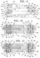
- the axes 28 and 29 of the exemplary embodiment according to FIGS. 9 to 11 can each be arranged and fixed in two different positions in the crank arm 12 or in the gear segment 9, as shown in FIGS. 10 and 11 is shown.
- edges 46 and 47 of the guide slot 39 of the gear segment 9 do not run at the same distance from one another.
- the edge 46 when the crank arm 12 is in the end position according to FIG. 1, runs concentrically to the axis line 48 of the axis 28 when the axis 28 is in the position shown in FIG. 10, in which the eccentricity is on the Gear segment 9 facing away.
- the edge 47 of the slot guide 39 runs concentrically to the axis line 48 of the axis 28 when it is in the position shown in FIG. 11.
- Collars 49 and 50 are arranged in the region of the guide slot 39, which cooperate with the outer contour of the axes 29, which are provided with a recess 51 on the side of their eccentricity.
- the collar 49 runs concentrically to the edge 46 of the slot guide 39, while the collar 50 runs concentrically to the edge 47 of the slot guide 39.
- the bolts of the screws 37 and 42 are guided on the edge 46 of the slot guide 39 and the axes 29 on the collar 49.
- the bolts of the screws 37, 42 are guided on the edge 47 of the slot guide 39 and the axes 29 on the collar 50. Adjusting the distance of the articulation point 25 relative to the axis 8 of the gear segment 9 thus does not lead to a change in the position of the gear segment.
- the coupling rod 13 is relatively long and the slot guide 39 is relatively short, the possible difference in the course of the edges 46 and 47 of the slot guide is in the order of magnitude of a necessary play of the screws 37 and 42 in the slot guide 39. In this case, then a slot guide 39 is used, the edges 46 and 47 of which are at a constant distance.
- a gripper drive 1 In a weaving machine with two rapiers, each of which is inserted into the shed from opposite sides a gripper drive 1 the task of bringing the weft thread from the entrance of the shed to the center thereof by means of a gripper, while the second gripper drive 1 with the second gripper 4 has the task of taking over the weft thread in the center of the shed and to the opposite side bring.
- So-called positive grippers which are opened by external opening elements for receiving or dispensing a weft thread, or so-called negative grippers, which do not necessarily have to be opened in order to pick up or discharge a weft thread, can be used.
- the crank arm 12, the coupling rod 13 and the gear segment 9 of the gripper drive 1 form a rod gear which converts the movement of the crank arm 12 into a movement of the gear segment 9.
- This rod gearbox contains a drive rod (connecting line between the axis 11 and the axis line 48 of the axis 28), an intermediate rod (connecting line of the axis line 48 of the axis 28 and the axis line of the axis 29) and an output rod (connecting line between the axis 29 and the axis 8 ).
- the course of the movement of a gripper that is driven by means of such a gripper drive 1 can be calculated using known kinematic equations.
- a different rod drive results, which specifies a different course of movement for the gear segment 9 and thus for the gripper 4. If the axes 28 and 29 are arranged in a position corresponding to FIG. 3 or 10 and the gripper drive moves from the end position shown in FIG. 2 to the end position shown in FIG. 1, the gripper 4 reaches a predetermined speed relatively quickly. Such a gripper drive 1 can therefore be used very well for a negative gripper. On the other hand, when the gripper drive 1 moves from the position shown in FIG. 2 and the axes 28 and 29 are fixed in a position corresponding to FIG. 6 or 11, the gripper 4 reaches the predetermined one Speed slower, so that the gripper drive 1 set in this way can advantageously be used with a positive gripper.
- crank arm 12 is not driven by means of a spatial gear, but rather by means of a cam gear, as is disclosed for example in FR-A 23 15 558.
- the crank arm 12 is driven by means of an eccentric gear or a rod gear.
- the articulation point 24 of the coupling rod 13 on the crank arm 12 can be brought into two different positions in the circumferential direction of its stationary axis 11 in that the axis 28 with which the coupling rod 13 on the crank arm 12 is mounted, is eccentric to the journal with which the axle is attached to the crank arm 12. If it should be provided that the articulation point 24 should be fixable on the crank arm 12 in several different settings, then other fastenings for the axis 28 are to be provided accordingly, which then also need not be arranged eccentrically for their fastening (journal 30). For example, it is possible to attach the axle 28 to a holder which is adjustable and fixable in a guide concentric with the axle 11 of the crank arm 12.
Landscapes
- Engineering & Computer Science (AREA)
- Textile Engineering (AREA)
- Looms (AREA)
Applications Claiming Priority (2)
| Application Number | Priority Date | Filing Date | Title |
|---|---|---|---|
| BE9500840 | 1995-10-11 | ||
| BE9500840A BE1009681A3 (nl) | 1995-10-11 | 1995-10-11 | Grijperaandrijving voor weefmachines. |
Publications (3)
| Publication Number | Publication Date |
|---|---|
| EP0768408A2 true EP0768408A2 (fr) | 1997-04-16 |
| EP0768408A3 EP0768408A3 (fr) | 1998-12-23 |
| EP0768408B1 EP0768408B1 (fr) | 2001-12-19 |
Family
ID=3889228
Family Applications (1)
| Application Number | Title | Priority Date | Filing Date |
|---|---|---|---|
| EP96116156A Expired - Lifetime EP0768408B1 (fr) | 1995-10-11 | 1996-10-09 | Dispositif d'entraínement des pinces pour un métier à tisser |
Country Status (4)
| Country | Link |
|---|---|
| US (1) | US5853032A (fr) |
| EP (1) | EP0768408B1 (fr) |
| BE (1) | BE1009681A3 (fr) |
| DE (1) | DE59608487D1 (fr) |
Cited By (3)
| Publication number | Priority date | Publication date | Assignee | Title |
|---|---|---|---|---|
| WO1998059187A1 (fr) * | 1997-06-24 | 1998-12-30 | Ralf Kaufmann | Dispositif, en particulier une pompe |
| DE10137183A1 (de) * | 2001-07-31 | 2003-02-20 | Staeubli Gmbh | Antriebsvorrichtung für Arbeitselemente an Webmaschinen |
| CN100532669C (zh) * | 2005-08-15 | 2009-08-26 | 绍兴纺织机械集团有限公司 | 新型剑杆织机 |
Families Citing this family (7)
| Publication number | Priority date | Publication date | Assignee | Title |
|---|---|---|---|---|
| DE10134504A1 (de) * | 2001-07-05 | 2003-01-16 | Picanol Nv | Verfahren und Vorrichtung zum Öffnen einer Greiferklemme eines Greifers einer Webmaschine |
| DE10346227B4 (de) * | 2003-09-23 | 2012-09-13 | Picanol N.V. | Greiferbandantrieb für eine Greiferwebmaschine |
| FR2906266B1 (fr) * | 2006-09-22 | 2008-12-19 | Schonherr Textilmaschb Gmbh | Dispositif de commande de lance flexible et metier a tisser incorporant au moins un tel dispositif |
| CN103643387A (zh) * | 2013-12-26 | 2014-03-19 | 聊城由甲纺织机械有限公司 | 一种剑杆织机曲柄齿轮t型摇杆钟摆式扇齿引纬装置 |
| EP4008817B1 (fr) | 2020-12-07 | 2024-07-17 | Picanol | Procédé et dispositif pour déterminer un paramètre de mouvement d'une pince |
| WO2022122272A1 (fr) | 2020-12-07 | 2022-06-16 | Picanol | Procédé et dispositif de réglage de la course de déplacement d'une pince |
| EP4008818B1 (fr) * | 2020-12-07 | 2024-07-17 | Picanol | Procédé de réglage de course de déplacement d'une pince à fil et dispositif d'entrainement d'une pince à fil |
Family Cites Families (10)
| Publication number | Priority date | Publication date | Assignee | Title |
|---|---|---|---|---|
| FR1105603A (fr) * | 1954-05-31 | 1955-12-06 | Dewatex | Dispositif de commande de passe-trame de métiers à tisser |
| LU42463A1 (fr) * | 1962-10-03 | 1964-04-03 | ||
| FR2315558A1 (fr) * | 1975-06-23 | 1977-01-21 | Placencia De Las Armas | Perfectionnements aux mecanismes pour la commande des lances passe-trame des metiers a tisser a reserve de trame fixe |
| US4526212A (en) * | 1980-04-11 | 1985-07-02 | Alamak Sa | Actuating device for reciprocating grippers in shuttleless looms |
| BE890571A (nl) * | 1981-10-01 | 1982-04-01 | Picanol Nv | Aandrijfinrichting voor een bandgrijper in een weefmachine |
| US4427037A (en) * | 1981-10-16 | 1984-01-24 | James Mackie & Sons Ltd. | Shuttleless looms |
| DE3604257C1 (de) * | 1986-02-11 | 1987-03-26 | Dornier Gmbh Lindauer | Getriebe fuer schuetzenlose Webmaschinen |
| US5001065A (en) * | 1987-05-27 | 1991-03-19 | Cetus Corporation | Human cell line and triomas, antibodies, and transformants derived therefrom |
| IT1204675B (it) * | 1987-06-03 | 1989-03-10 | Colombo Filippetti Srl | Dispositivo per la trasformazione di un moto rotatorio uniforme in un moto rotatorio alternativo,particolarmente adatto per telai tessili |
| IT1222533B (it) * | 1987-08-24 | 1990-09-05 | Nuovo Pignone Spa | Dispositivo di azionamento dei nastri portapinze per un telaio tessile senza navette |
-
1995
- 1995-10-11 BE BE9500840A patent/BE1009681A3/nl not_active IP Right Cessation
-
1996
- 1996-10-09 EP EP96116156A patent/EP0768408B1/fr not_active Expired - Lifetime
- 1996-10-09 DE DE59608487T patent/DE59608487D1/de not_active Expired - Fee Related
- 1996-10-11 US US08/729,150 patent/US5853032A/en not_active Expired - Fee Related
Cited By (3)
| Publication number | Priority date | Publication date | Assignee | Title |
|---|---|---|---|---|
| WO1998059187A1 (fr) * | 1997-06-24 | 1998-12-30 | Ralf Kaufmann | Dispositif, en particulier une pompe |
| DE10137183A1 (de) * | 2001-07-31 | 2003-02-20 | Staeubli Gmbh | Antriebsvorrichtung für Arbeitselemente an Webmaschinen |
| CN100532669C (zh) * | 2005-08-15 | 2009-08-26 | 绍兴纺织机械集团有限公司 | 新型剑杆织机 |
Also Published As
| Publication number | Publication date |
|---|---|
| DE59608487D1 (de) | 2002-01-31 |
| EP0768408A3 (fr) | 1998-12-23 |
| US5853032A (en) | 1998-12-29 |
| EP0768408B1 (fr) | 2001-12-19 |
| BE1009681A3 (nl) | 1997-06-03 |
Similar Documents
| Publication | Publication Date | Title |
|---|---|---|
| DE4430184C2 (de) | Axialgewinderollkopf | |
| DE1026134B (de) | Vorrichtung zur loesbaren Sicherung von Raedern gegen Axialverschiebung | |
| DE69308207T2 (de) | Futter-Mechanismus | |
| EP0953073B1 (fr) | Mecanisme d'entrainement pour metier mecanique | |
| DE3727147A1 (de) | Nachspannendes bohrfutter | |
| DE2102412C3 (de) | Verstellvorrichtung an Kurbelwellenschleifmaschinen zum Ausrichten der zu schleifenden Kurbelzapfen | |
| DE3503112C2 (fr) | ||
| DE3324494C1 (de) | Walzwerkzeug | |
| EP0768408B1 (fr) | Dispositif d'entraínement des pinces pour un métier à tisser | |
| DE1710190B2 (de) | Steuervorrichtung fuer die schaefte von webmaschinen | |
| DE4423932B4 (de) | Vorrichtung zum Schnellwechseln eines Spannzeugs einer Werkzeugmaschine | |
| DE69315771T2 (de) | Planetenrollen-Vorschubkopf | |
| EP0377860B1 (fr) | Tambour de transfert de feuilles pour machines à imprimer pour l'impression sur le premier côté ou en retiration | |
| DE4037130A1 (de) | Vorrichtung zum verstellen der falzklappen an einem falzklappenzylinder | |
| EP0193876A2 (fr) | Unité d'entraînement pour outils rotatifs | |
| DE4214838C2 (de) | Spannfutter | |
| DE4421890A1 (de) | Spannfutter mit einem Mitnehmer | |
| EP0480879B1 (fr) | Dispositif de réglage continu du mouvement de distribution axial de rouleaux distributeurs | |
| DE10022232A1 (de) | Antriebsvorrichtung für eine Nähmaschine | |
| DE3018633C2 (de) | Elektrobohrhammer mit abschaltbarem Bohrantrieb | |
| EP1118462B1 (fr) | Cylindre dans un dispositif pour la fabrication de formes d'impression | |
| EP0155987A2 (fr) | Outil de rotation et de réglage pour pièces à symétrie axiale, en particulier pour bancs de direction de véhicule | |
| DE102010050612B4 (de) | Drehantriebsvorrichtung | |
| DE3405455C1 (de) | Umfangsregister-Einstellvorrichtung an Rotationsdruckmaschinen | |
| DE3879226T2 (de) | Eine greifende und rotierende zangenanordnung. |
Legal Events
| Date | Code | Title | Description |
|---|---|---|---|
| PUAI | Public reference made under article 153(3) epc to a published international application that has entered the european phase |
Free format text: ORIGINAL CODE: 0009012 |
|
| AK | Designated contracting states |
Kind code of ref document: A2 Designated state(s): BE CH DE FR GB IT LI |
|
| PUAL | Search report despatched |
Free format text: ORIGINAL CODE: 0009013 |
|
| AK | Designated contracting states |
Kind code of ref document: A3 Designated state(s): BE CH DE FR GB IT LI |
|
| 17P | Request for examination filed |
Effective date: 19990204 |
|
| GRAG | Despatch of communication of intention to grant |
Free format text: ORIGINAL CODE: EPIDOS AGRA |
|
| 17Q | First examination report despatched |
Effective date: 20001006 |
|
| GRAG | Despatch of communication of intention to grant |
Free format text: ORIGINAL CODE: EPIDOS AGRA |
|
| GRAH | Despatch of communication of intention to grant a patent |
Free format text: ORIGINAL CODE: EPIDOS IGRA |
|
| GRAH | Despatch of communication of intention to grant a patent |
Free format text: ORIGINAL CODE: EPIDOS IGRA |
|
| GRAA | (expected) grant |
Free format text: ORIGINAL CODE: 0009210 |
|
| AK | Designated contracting states |
Kind code of ref document: B1 Designated state(s): BE CH DE FR GB IT LI |
|
| PG25 | Lapsed in a contracting state [announced via postgrant information from national office to epo] |
Ref country code: GB Free format text: LAPSE BECAUSE OF FAILURE TO SUBMIT A TRANSLATION OF THE DESCRIPTION OR TO PAY THE FEE WITHIN THE PRESCRIBED TIME-LIMIT Effective date: 20011219 |
|
| REG | Reference to a national code |
Ref country code: CH Ref legal event code: NV Representative=s name: PATENTANWALTSBUERO G. PETSCHNER Ref country code: CH Ref legal event code: EP |
|
| REG | Reference to a national code |
Ref country code: GB Ref legal event code: IF02 |
|
| REF | Corresponds to: |
Ref document number: 59608487 Country of ref document: DE Date of ref document: 20020131 |
|
| ET | Fr: translation filed | ||
| GBV | Gb: ep patent (uk) treated as always having been void in accordance with gb section 77(7)/1977 [no translation filed] |
Effective date: 20011219 |
|
| PLBE | No opposition filed within time limit |
Free format text: ORIGINAL CODE: 0009261 |
|
| STAA | Information on the status of an ep patent application or granted ep patent |
Free format text: STATUS: NO OPPOSITION FILED WITHIN TIME LIMIT |
|
| 26N | No opposition filed | ||
| PGFP | Annual fee paid to national office [announced via postgrant information from national office to epo] |
Ref country code: BE Payment date: 20061023 Year of fee payment: 11 |
|
| PGFP | Annual fee paid to national office [announced via postgrant information from national office to epo] |
Ref country code: CH Payment date: 20061024 Year of fee payment: 11 |
|
| PGFP | Annual fee paid to national office [announced via postgrant information from national office to epo] |
Ref country code: IT Payment date: 20061031 Year of fee payment: 11 |
|
| PGFP | Annual fee paid to national office [announced via postgrant information from national office to epo] |
Ref country code: DE Payment date: 20061208 Year of fee payment: 11 |
|
| REG | Reference to a national code |
Ref country code: CH Ref legal event code: NV Representative=s name: ZIMMERLI, WAGNER & PARTNER AG |
|
| BERE | Be: lapsed |
Owner name: PICANOL N.V. Effective date: 20071031 |
|
| REG | Reference to a national code |
Ref country code: CH Ref legal event code: PL |
|
| PG25 | Lapsed in a contracting state [announced via postgrant information from national office to epo] |
Ref country code: LI Free format text: LAPSE BECAUSE OF NON-PAYMENT OF DUE FEES Effective date: 20071031 Ref country code: DE Free format text: LAPSE BECAUSE OF NON-PAYMENT OF DUE FEES Effective date: 20080501 Ref country code: CH Free format text: LAPSE BECAUSE OF NON-PAYMENT OF DUE FEES Effective date: 20071031 |
|
| PG25 | Lapsed in a contracting state [announced via postgrant information from national office to epo] |
Ref country code: BE Free format text: LAPSE BECAUSE OF NON-PAYMENT OF DUE FEES Effective date: 20071031 |
|
| REG | Reference to a national code |
Ref country code: FR Ref legal event code: ST Effective date: 20080630 |
|
| PGFP | Annual fee paid to national office [announced via postgrant information from national office to epo] |
Ref country code: FR Payment date: 20061020 Year of fee payment: 11 |
|
| PG25 | Lapsed in a contracting state [announced via postgrant information from national office to epo] |
Ref country code: FR Free format text: LAPSE BECAUSE OF NON-PAYMENT OF DUE FEES Effective date: 20071031 |
|
| PG25 | Lapsed in a contracting state [announced via postgrant information from national office to epo] |
Ref country code: IT Free format text: LAPSE BECAUSE OF NON-PAYMENT OF DUE FEES Effective date: 20071009 |