EP0768451B1 - Catalyseur monolithique et procédé pour sa préparation - Google Patents
Catalyseur monolithique et procédé pour sa préparation Download PDFInfo
- Publication number
- EP0768451B1 EP0768451B1 EP96116257A EP96116257A EP0768451B1 EP 0768451 B1 EP0768451 B1 EP 0768451B1 EP 96116257 A EP96116257 A EP 96116257A EP 96116257 A EP96116257 A EP 96116257A EP 0768451 B1 EP0768451 B1 EP 0768451B1
- Authority
- EP
- European Patent Office
- Prior art keywords
- tube
- shaped
- shaped workpiece
- monolithic catalyst
- sealing member
- Prior art date
- Legal status (The legal status is an assumption and is not a legal conclusion. Google has not performed a legal analysis and makes no representation as to the accuracy of the status listed.)
- Expired - Lifetime
Links
Images


Classifications
-
- F—MECHANICAL ENGINEERING; LIGHTING; HEATING; WEAPONS; BLASTING
- F01—MACHINES OR ENGINES IN GENERAL; ENGINE PLANTS IN GENERAL; STEAM ENGINES
- F01N—GAS-FLOW SILENCERS OR EXHAUST APPARATUS FOR MACHINES OR ENGINES IN GENERAL; GAS-FLOW SILENCERS OR EXHAUST APPARATUS FOR INTERNAL-COMBUSTION ENGINES
- F01N3/00—Exhaust or silencing apparatus having means for purifying, rendering innocuous, or otherwise treating exhaust
- F01N3/08—Exhaust or silencing apparatus having means for purifying, rendering innocuous, or otherwise treating exhaust for rendering innocuous
- F01N3/10—Exhaust or silencing apparatus having means for purifying, rendering innocuous, or otherwise treating exhaust for rendering innocuous by thermal or catalytic conversion of noxious components of exhaust
- F01N3/24—Exhaust or silencing apparatus having means for purifying, rendering innocuous, or otherwise treating exhaust for rendering innocuous by thermal or catalytic conversion of noxious components of exhaust characterised by constructional aspects of converting apparatus
- F01N3/28—Construction of catalytic reactors
- F01N3/2839—Arrangements for mounting catalyst support in housing, e.g. with means for compensating thermal expansion or vibration
- F01N3/2853—Arrangements for mounting catalyst support in housing, e.g. with means for compensating thermal expansion or vibration using mats or gaskets between catalyst body and housing
- F01N3/2857—Arrangements for mounting catalyst support in housing, e.g. with means for compensating thermal expansion or vibration using mats or gaskets between catalyst body and housing the mats or gaskets being at least partially made of intumescent material, e.g. unexpanded vermiculite
-
- F—MECHANICAL ENGINEERING; LIGHTING; HEATING; WEAPONS; BLASTING
- F01—MACHINES OR ENGINES IN GENERAL; ENGINE PLANTS IN GENERAL; STEAM ENGINES
- F01N—GAS-FLOW SILENCERS OR EXHAUST APPARATUS FOR MACHINES OR ENGINES IN GENERAL; GAS-FLOW SILENCERS OR EXHAUST APPARATUS FOR INTERNAL-COMBUSTION ENGINES
- F01N2450/00—Methods or apparatus for fitting, inserting or repairing different elements
- F01N2450/02—Fitting monolithic blocks into the housing
-
- Y—GENERAL TAGGING OF NEW TECHNOLOGICAL DEVELOPMENTS; GENERAL TAGGING OF CROSS-SECTIONAL TECHNOLOGIES SPANNING OVER SEVERAL SECTIONS OF THE IPC; TECHNICAL SUBJECTS COVERED BY FORMER USPC CROSS-REFERENCE ART COLLECTIONS [XRACs] AND DIGESTS
- Y10—TECHNICAL SUBJECTS COVERED BY FORMER USPC
- Y10T—TECHNICAL SUBJECTS COVERED BY FORMER US CLASSIFICATION
- Y10T29/00—Metal working
- Y10T29/49—Method of mechanical manufacture
- Y10T29/49345—Catalytic device making
Definitions
- the present invention relates to a process for manufacturing a monolithic catalyst converter, and according to the preamble of claim 1.
- a monolithic catalyst converter includes a catalyst container connected with the pipes of an exhaust system, and a monolithic catalyst held in the container.
- the clamshell monolithic catalyst converter is manufactured in the following manner: an upper member and a lower member are formed by pressing. Both of the upper and lower members are formed like a bowl, and have a flange which is formed all around the periphery to constitute a mating surface. Then, a monolithic catalyst is held in the upper and lower members. Finally, the upper and lower members holding the monolithic catalyst therein are welded at the flanges.
- the upper and lower members constitute a catalyst container including a tube-shaped member, and a pair of funnel-shaped cone members; the tube-shaped member holds the monolithic catalyst support therein; and the funnel-shaped cone members have a diametrically-reduced opening which is connected with a pipe of an exhaust system.
- the catalyst container made of the upper and lower members is likely to be distorted by thermal influences during welding, and might accordingly be damaged in terms of assembly operability with respect to the exhaust pipes of the exhaust system.
- welded portions remain in the tube-shaped member of the catalyst container as bonded portions which face each other in an axial direction thereof, and they also remain in the funnel-shaped cone members as bonded portions which face each other in a radial direction thereof
- the welded portions result from the welding of the upper and lower member at their flanges. Therefore, in order to securely inhibit the exhaust gases from leaking through all of the bonded portions, the clamshell monolithic catalyst converter should be inspected by a troublesome leak test whether all of the bonded portions are formed in an air-proof manner.
- the flow of exhaust gases is likely to be disturbed by the bonded portions in the catalyst container.
- the disturbed flow increases exhaust resistance, and might eventually deteriorate the output of engines.
- the deterioration of engine output results mainly from the bonded portions which extend radially in the funnel-shaped cone members.
- the welded portions result in the bonded portions which extend in a circumferential direction in the tube-shaped member and the cone-shaped members. It is also believed that these circumferentially-extending bonded portions cause problems similar to those caused by the axially-extending boded portions.
- the upper and lower members should be provided with a flange which is formed all around the periphery to constitute a mating surface, and should be welded together at the flanges over a long distance by expensive welding facilities.
- the material cost and the welding cost are so high that they push up the overall manufacturing cost.
- Japanese Unexamined Patent Publication (KOKAI) No. 2-264,110 proposes a monolithic catalyst converter whose catalyst container is one-piece.
- a one-piece catalyst container is manufactured in the following manner: a tube-shaped workpiece is pressed at the opposite ends to form an inlet port and upper and lower closure ends which extend outwardly from the inlet port to the opposite sides, and an outlet port and upper and lower closure ends which extend outwardly from the outlet port to the opposite sides. Thereafter, at the opposite ends of the pressed tube-shaped workpiece, all of the upper and lower closure ends are welded together to complete a one-piece catalyst container.
- the catalyst container is formed integrally out of a tube-shaped workpiece. Therefore, in manufacturing the monolithic catalyst converter, the welding can be carried out over a reduced length at the opposite upper and lower closure ends. Thus, it is somehow possible to reduce the manufacturing cost, and to achieve a good working environment,
- the welded portions resulting from welding the opposite upper and lower closure ends, remain as bonded portions which extend in a radial direction.
- the monolithic catalyst converter has been adversely affected by the thermal influences in the welding operations, and accordingly it little exhibits perfect assembly operability with respect the exhaust pipes of the exhaust system.
- the following problems are believed to arise from the radially-extending bonded portions: namely; they make the air-proof inspection indispensable; and they deteriorate the output of engines.
- the radially-extending bonded portions cannot reduce the manufacturing cost and establish a good working environment completely.
- the present invention has been developed in view of the aforementioned circumstances. It is therefore an object of the present invention to provide a process for manufacturing a monolithic catalyst converter which can exhibit satisfactory assembly operability with respect to the exhaust pipes of an exhaust system, which can obviate the tiresome air-proof inspection, and which can inhibit the engine-output deterioration caused by the turbulence of exhaust gases, wherein the process for manufacturing such a monolithic catalyst converter should be carried out at a reduced cost and under a good working environment.
- This object is achieved by the process as defined in claim 1.
- the tube-shaped member and the funnel-shaped cone members are formed integrally and free from welding to constitute the catalyst container.
- the catalyst container is free from the bonded portions which result from the welded portions, and which extend in an axial direction, in a radial direction or in a circumferential direction.
- a tube-shaped workpiece can be employed. Excepting the case where a seamless tube-shaped workpiece can be employed, the tube-shaped workpiece is usually prepared by winding a plate-shaped workpiece in a tubular manner. Thus, an axially-extending bonded portion may be present in the thus prepared tube-shaped workpiece originally. Hence, it is preferred to employ a seamless tube-shaped workpiece as the tube-shaped workpiece. Note that, however, even if the tube-shaped workpiece is a seamed tube-shaped workpiece which is commercially available in general, its axially-extending bonded portion does hardly impair the air-tightness of the resultant catalyst container even after it is processed completely.
- the term, "bonded portion”, does not involve the bonded portions which have been existing in tube-shaped workpieces originally.
- the tube-shaped member and the funnel-shaped cone members can be formed free from welding and integrally out of a tube-shaped workpiece which originally involves an axially-extending welded portion therein.
- the catalyst container of the present monolithic catalyst converter can be prepared out of a seamless tube-shaped workpiece or a seamed tube-shaped workpiece. Therefore, in the phrase, "formed free from welding”, the term, “welding”, does not mean the welding operation in which a plate-shaped or sheet-shaped workpiece is welded to a tube-shaped workpiece.
- the present monolithic catalyst converter is manufactured without carrying out the welding operation, which has been done conventionally, at all. Therefore, the catalyst container is little distorted by the thermal influences which result from the welding operation.
- the present monolithic catalyst converter is free from the bonded portions which have existed in the conventional clamshell monolithic catalyst converters. Consequently, without ever subjecting the present monolithic catalyst converter to the troublesome leak-test inspection which has been carried out conventionally, it is possible to reliably inhibit the exhaust gases from leaking.
- the catalyst container of the present monolithic catalyst converter there are no bonded portions which have been present in the catalyst container of the conventional clamshell monolithic catalyst converters. As a result, it is possible to smoothly flow the exhaust gases in the catalyst container.
- the present monolithic catalyst converter manufactured by the process of claim 1 and therefore is free from the bonded portions which have resulted from the welding operation has the following advantages: it can exhibit favorable assembly operability with respect to the exhaust pipes of an exhaust system; it can obviate the tiresome air-proof inspection; and it can inhibit the engine-output deterioration which has been caused by the turbulence of the exhaust gases.
- the process for manufacturing a monolithic catalyst converter can be selectively carried out in the following two distinct manners:
- the monolithic catalyst converter Summing up, it is possible to manufacture the monolithic catalyst converter with the above advantages.
- the catalyst container is formed integrally out of the tube-shaped workpiece, and free from welding. Accordingly, in manufacturing the present monolithic catalyst, it is possible to reduce the material cost, and to obviate the conventional welding operation.
- the manufacturing process in particular effects the following advantages: it can reduce the material cost; and it can obviate the conventional welding operation. Consequently, the present monolithic-catalyst-converter-manufacturing process can complete the monolithic catalyst converter according to the first aspect of the present invention at a reduced manufacturing cost under a good environment.
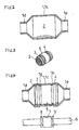
- a tube-shaped workpiece 1, and a monolithic catalyst 2 are prepared, the preparation of the calalyst 2 being described in more detail with regard to figure 4.
- the tube-shaped workpiece 1 was made from a stainless steel, and prepared by winding a plate-shaped workpiece in a tubular manner. Thus, an axially-extending welded portion remains in the tube-shaped workpiece 1 originally.
- the monolithic catalyst 1 includes a ceramics support employed as a support substrate, a catalyst carrier layer formed of ceramics and disposed on the ceramics support, and a catalyst ingredient, such as platinum, or the like, loaded on the catalyst carrier layer.
- the metallic support herein includes a honeycomb substance which is formed by winding a corrugated plate and a flat plate, and an outer tube for holding the honeycomb substance therein.
- a monolithic catalyst 2 is fitted into the inside of the tube-shaped workpiece 1 through another opposite end opening 1b.
- the tube-shaped workpiece 1 is drawn into a funnel shape at an opposite opening end 1a.
- a spinning apparatus 1 shown in Fig.5 is employed.
- a chuck 20 can hold a tube-shaped workpiece 1 so that an opposite opening end 1a of the tube-shaped workpiece 1 extends horizontally.
- the chuck 20 is fastened to a rotary shaft of a motor 21.
- the tube-shaped workpiece 1 is disposed rotatably about its axial center line.
- a vertically movable table 23 which can be moved vertically by a hydraulic cylinder 22.
- the vertically movable table 23 is provided with a horizontally movable table 25 which can be moved horizontally by a hydraulic cylinder 24.
- the horizontally movable table 25 is provided with a roller 27 by way of a bracket 26.
- the roller 27 has an axial center line which is parallel to that of the tube-shaped workpiece 1, and accordingly can be driven as the tube-shaped workpiece 1 rotates.
- the tube-shaped workpiece 1 is drawn into a funnel shape at the opposite opening end 1a.
- the tube-shaped workpiece 1 is rotated about the axial center line by the motor 21, and simultaneously the roller 27 is pressed gradually but heavily onto the opposite opening end 1a of the tube-shaped workpiece 1 by controlling the operations of the hydraulic cylinders 22 and 24.
- the alternative drawing operation is thus completed at the opposite end opening 1a of the tube-shaped workpiece 1. Note that, in the alternative drawing operation as well, it is possible to locally heat or anneal the opposite end opening 1a in order to improve the forming ability.
- the opposite end opening 1b of the tube-shaped workpiece 1 is drawn by using the drawing apparatus with dies, or by using the spinning drawing apparatus.
- the opposite end opening 1b is drawn into a funnel-shaped cone member 1e.
- the tube-shaped member 1c is constituted by the portion of the tube-shaped workpiece 1 excepting the cone members 1d and 1e.
- FIG. 3 An intermediate product of a monolithic catalyst converter is thus manufactured as illustrated Fig. 3.
- the tube-shaped member 1c, and the opposite cone members 1d and 1e are formed integrally out of the tube-shaped workpiece 1 so as to constitute the catalyst container 1.
- the monolithic catalyst 2 is held in the tube-shaped member 1c.
- the opposite cone members 1d and 1e are connected with the pipes of an exhaust system at their diametrically-reduced openings.
- a monolithic catalyst 2 is first fitted into a tube-shaped workpiece 1 through either an opposite end opening 1a or another opposite opening end 1b.
- the opposite end openings 1a and 1b of the tube-shaped workpiece 1 are drawn continuously by using the spinning drawing apparatus (shown in Fig.5).
- the opposite end openings 1a and 1b are drawn into funnel-shaped cone members 1d and 1e.
- the drawing step of the Second Preferred Embodiment was carried out in the same manner as the First Preferred Embodiment.
- the drawing operation can be carried out continuously. Therefore, it is possible to reduce the overall manufacturing time.
- the monolithic catalyst 2 is provided with ring-shaped holding members 3 and 4.
- the ring-shaped holding members 3 and 4 are fastened onto the peripheral surface of the opposite-end sides of the monolithic catalyst 2, and include an aggregate of stainless steel fibers which exhibit a larger thermal expansion coefficient than that of a tube-shaped workpiece 1.
- the monolithic catalyst 2 is provided with a sealing member 5.
- the sealing member 5 is wound around the middle peripheral surface of the monolithic catalyst 2, and includes ceramics fibers and vermiculite.
- the monolithic catalyst 2 with the extra component parts provided is fitted into a tube-shaped workpiece 1, instead of the monolithic catalyst 2 as shown in a simplified manner in figure 1.
- the pressing jig includes a shaft 6, a major-width roller 7 which is disposed around the shaft 6, and a pair of minor-width rollers 8 and 9 which are disposed around the shaft 6 on both sides of the roller 7.
- the major-width roller 7 has a width which is slightly smaller than that of the sealing member 5.
- the minor-width rollers 8 and 9 has a width which is smaller than the interval between the sealing member 5 and the ring-shaped holding members 3 and 4.
- the pressing jig is constructed so that the minor-width roller 8 can be positioned between the holding member 3 and the sealing member 5, and so that the minor-width roller 9 can be positioned between the holding member 4 and the sealing member 5.
- the tube-shaped workpiece 1 and the pressing jig are rotated about the axial center line, and are pressed against each other. Accordingly, the roller 8 plastically deforms the tube-shaped member 1c between the holding member 3 and the sealing member 5, and the roller 9 plastically deforms the tube-shaped member 1c between the holding member 4 and the sealing member 5. Thus, a ring-shaped indentation 1g, and a ring-shaped indentation 1h are formed between the holding member 3 and the sealing member 5, and between the holding member 4 and the sealing member 5, respectively. Moreover, the roller 7 plastically deforms the tube-shaped workpiece 1 between the indentations 1g and 1h. Thus, the tube-shaped member 1c is reduced diametrically between the indentations 1g and 1h.
- a monolithic catalyst converter is thus finally manufactured.
- the holding members 3 and 4 thermally expand greater than the catalyst container 1 does, and clamp the indentations 1g and 1h of the tube-shaped member 1c between themselves and the sealing member 5. Therefore, the monolithic catalyst 2 can be held firmly in the catalyst container 1.
- the sealing member 5 expands and solidifies between the indentations 1g and 1h where the tube-shaped member 1c is reduced diametrically, and accordingly exhibits a large resilient force.
- the monolithic catalyst converter can effect not only high rigidity for holding the monolithic catalyst 2, but also high air-tightness.
- the holding member 3 or 4 is disposed on the exhaust-gas-inlet side of the monolithic catalyst converter, and can inhibit the exhaust gases of elevated temperatures from degrading the sealing member 5.
- the monolithic catalyst produced as described above has the following advantages: Because it is not subjected to the welding operation which has been carried out conventionally: namely; its catalyst container 1 is little distorted by the thermal influences resulting from the welding operation; and it enables to assemble the opposite cone members 1d and 1e with good operability.
- the monolithic catalyst converter is free from the axially-extending bonded portions, the radially extending bonded portions, and the circumferentially-extending bonded portions which result from the welded members. Therefore, it is not necessary to subject the monolithic catalyst converter to the troublesome leak-test inspection which has been carried out conventionally. Indeed, the monolithic catalyst converter can securely inhibit the exhaust gases from leaking, and can be manufactured with a high material yield (or a low scrap rate).
- the material cost is reduced in manufacturing the monolithic catalyst converter, and the welding operation has been obviated therein.
- the monolithic catalyst converter enables to reduce the manufacturing cost, and to realize a good working environment.
- the monolithic catalyst converter takes in the exhaust gases, emitted from engines by way of the inlet pipe of the exhaust system, to introduce them to the monolithic catalyst 2, and the monolithic catalyst 2 purifies the harmful components involved in the exhaust gases.
- the exhaust gases can flow smoothly in the catalyst container 1, because the monolithic catalyst converter has no bonded portions in the catalyst container 1.
- Such bonded portions have existed inevitably in the catalyst container of the conventional clamshell monolithic catalyst converters.
- the monolithic catalyst converter can inhibit the exhaust resistance from increasing, and accordingly can keep the engine output from deteriorating.
Landscapes
- Chemical & Material Sciences (AREA)
- Chemical Kinetics & Catalysis (AREA)
- Engineering & Computer Science (AREA)
- Health & Medical Sciences (AREA)
- Toxicology (AREA)
- Combustion & Propulsion (AREA)
- Mechanical Engineering (AREA)
- General Engineering & Computer Science (AREA)
- Exhaust Gas After Treatment (AREA)
- Catalysts (AREA)
Claims (9)
- Procédé de fabrication d'un pot à catalyseur monolithique, comprenant les étapes consistant à :caractérisé parengager un catalyseur monolithique (2) dans une pièce d'ouvrage en forme de tube (1) comportant des extrémités d'ouvertures opposées (1a, 1b) par l'intermédiaire de l'une des extrémités d'ouvertures opposées (1a, 1b),
avant ladite étape d'engagement du catalyseur monolithique, la disposition d'un élément d'étanchéité (5) sur une surface périphérique intermédiaire du catalyseur monolithique (2), et d'un élément de maintien en forme d'anneau (3, 4) à l'écart de l'élément d'étanchéité, de chaque côté des côtés d'extrémités opposés de l'élément d'étanchéité (5),
l'étirement de la pièce d'ouvrage en forme de tube (1) au niveau des extrémités d'ouvertures opposées (1a, 1b) suivant une forme d'entonnoir au moyen d'un fluotournage, et
après ladite étape d'étirement de la pièce d'ouvrage en forme de tube, le sertissage de la pièce d'ouvrage en forme de tube (1) au niveau d'une partie qui est positionnée entre l'élément d'étanchéité (5) et l'élément de maintien en forme d'anneau (3, 4),
en achevant ainsi le pot à catalyseur monolithique sans exécuter de soudage. - Procédé selon la revendication 1, dans lequel dans ladite étape d'étirement de la pièce d'ouvrage en forme de tube, après ladite étape d'engagement du catalyseur monolithique, la pièce d'ouvrage en forme de tube (1) est étirée de façon continue au niveau des extrémités d'ouvertures opposées (1a, 1b) suivant une forme d'entonnoir.
- Procédé selon la revendication 1 ou 2, dans lequel dans ladite étape de disposition, une paire des éléments de maintien en forme d'anneau (3, 4) est disposée à l'écart de l'élément d'étanchéité (5) de chacun des deux côtés d'extrémités opposés de l'élément d'étanchéité (5), et
dans ladite étape de sertissage, la pièce d'ouvrage en forme de tube (1) est sertie au niveau de parties (1j, 1h) qui sont positionnées respectivement entre l'élément d'étanchéité (5) et l'un des éléments de maintien en forme d'anneau (3, 4), et entre l'élément d'étanchéité (5) et un autre des éléments en forme d'anneau (3, 4). - Procédé selon l'une des revendications 1 à 3, dans lequel ladite étape de sertissage est exécutée au moyen de l'application d'une roulette.
- Procédé selon l'une des revendications 1 à 4, dans lequel avant ladite étape d'étirement de la pièce d'ouvrage en forme de tube, la pièce d'ouvrage en forme de tube (1) est traitée localement thermiquement au niveau des ouvertures d'extrémités opposées (1a, 1b).
- Procédé selon l'une des revendications 1 à 5, dans lequel, dans ladite étape d'étirement de la pièce d'ouvrage en forme de tube, la pièce d'ouvrage en forme de tube (1) est traitée localement thermiquement au niveau des ouvertures d'extrémités opposées (1a, 1b).
- Procédé selon l'une des revendications 1 à 6, dans lequel la pièce d'ouvrage en forme de tube (1) est maintenue et entraínée en rotation par un mandrin (20) et est étirée en une forme d'entonnoir au niveau des extrémités d'ouvertures opposées (1a, 1b) par un galet (27) disposé avec possibilité de rotation.
- Procédé selon l'une des revendications 1 à 7, dans lequel ledit élément d'étanchéité (5) est formé d'un matériau qui se dilate et se solidifie à des températures élevées.
- Procédé selon l'une des revendications 1 à 8, dans lequel ledit élément de maintien (3, 4) présente un coefficient de dilatation thermique qui est supérieur à celui de ladite pièce d'ouvrage en forme de tube (1).
Applications Claiming Priority (3)
| Application Number | Priority Date | Filing Date | Title |
|---|---|---|---|
| JP264383/95 | 1995-10-12 | ||
| JP26438395 | 1995-10-12 | ||
| JP26438395A JP3585064B2 (ja) | 1995-10-12 | 1995-10-12 | モノリス触媒コンバータ及びその製造方法 |
Publications (3)
| Publication Number | Publication Date |
|---|---|
| EP0768451A1 EP0768451A1 (fr) | 1997-04-16 |
| EP0768451B1 true EP0768451B1 (fr) | 2002-09-11 |
| EP0768451B2 EP0768451B2 (fr) | 2006-03-29 |
Family
ID=17402399
Family Applications (1)
| Application Number | Title | Priority Date | Filing Date |
|---|---|---|---|
| EP96116257A Expired - Lifetime EP0768451B2 (fr) | 1995-10-12 | 1996-10-10 | Catalyseur monolithique et procédé pour sa préparation |
Country Status (5)
| Country | Link |
|---|---|
| US (1) | US5953817A (fr) |
| EP (1) | EP0768451B2 (fr) |
| JP (1) | JP3585064B2 (fr) |
| KR (1) | KR100188451B1 (fr) |
| DE (1) | DE69623556T3 (fr) |
Families Citing this family (46)
| Publication number | Priority date | Publication date | Assignee | Title |
|---|---|---|---|---|
| EP0818615B1 (fr) * | 1996-07-10 | 2011-09-28 | Volkswagen Aktiengesellschaft | Boîtier de catalyseur |
| US5937516A (en) * | 1996-12-13 | 1999-08-17 | General Motors Corporation | Method for spin forming articles |
| EP0859133B1 (fr) * | 1997-02-12 | 2003-09-03 | Corning Incorporated | Procédé de fabrication d'un pot catalytique pour un moteur à combustion interne |
| US5980837A (en) * | 1997-12-03 | 1999-11-09 | Ford Global Technologies, Inc. | Exhaust treatment device for automotive vehicle having one-piece housing with integral inlet and outlet gas shield diffusers |
| JP2957163B1 (ja) | 1998-05-28 | 1999-10-04 | 株式会社三五 | 排気系部品とその製造方法 |
| AU2034800A (en) * | 1998-12-18 | 2000-07-12 | Corning Incorporated | A catalytic converter for use in an internal combustion engine and a method of making |
| US6381843B1 (en) * | 1999-08-03 | 2002-05-07 | Sango Co., Ltd. | Method of producing a catalytic converter |
| US6591498B2 (en) * | 1999-08-03 | 2003-07-15 | Sango Co., Ltd. | Method of producing a catalytic converter |
| JP3367939B2 (ja) * | 1999-08-03 | 2003-01-20 | 株式会社三五 | 触媒コンバータの製造方法 |
| US6324758B1 (en) | 2000-01-13 | 2001-12-04 | Visteon Global Tech., Inc. | Method for making a catalytic converter canister |
| DE10002218A1 (de) * | 2000-01-20 | 2001-07-26 | Eberspaecher J Gmbh & Co | Abgaskatalysator |
| US6332273B1 (en) | 2000-03-13 | 2001-12-25 | Visteon Global Tech., Inc. | Method for making a catalytic converter assembly |
| US6588293B2 (en) * | 2000-04-14 | 2003-07-08 | Nsk Ltd. | Hollow rack shaft |
| US6484397B1 (en) * | 2000-07-11 | 2002-11-26 | Corning Incorporated | Method of assembling a catalytic converter for use in an internal combustion engine |
| JP2002153930A (ja) | 2000-09-06 | 2002-05-28 | Toyota Motor Corp | 中空部材、その製造方法、その中空部材を用いた流体流通システム、および中空状材の成形装置 |
| DE10055728A1 (de) * | 2000-11-10 | 2002-05-23 | Volkswagen Ag | Metallkatalysator für eine Abgasanlage |
| JP2002161726A (ja) * | 2000-11-29 | 2002-06-07 | Ibiden Co Ltd | 排気ガス浄化装置及びその製造方法、セラミックハニカム構造体の収容構造 |
| US6732429B2 (en) * | 2000-12-05 | 2004-05-11 | Visteon Global Technologies, Inc. | Method for measuring pressure on the substrate of spin formed catalytic converter |
| JP4698890B2 (ja) * | 2001-03-28 | 2011-06-08 | 坂本工業株式会社 | 異形管の突出部の加工方法 |
| FR2826301B1 (fr) * | 2001-06-20 | 2003-10-24 | Faurecia Sys Echappement | Procede de fabrication d'un element etage d'une ligne d'echappement et element etage obtenu |
| KR100444661B1 (ko) * | 2001-07-11 | 2004-08-18 | 현대자동차주식회사 | 자동차용 촉매 컨버터의 제조방법 |
| EP1283333B1 (fr) * | 2001-08-10 | 2005-04-06 | Leifeld Metal Spinning GmbH | Procédé pour la production d'un pot catalytique |
| WO2003036057A1 (fr) * | 2001-10-26 | 2003-05-01 | Donaldson Company, Inc. | Appareil central de traitement de gaz d'echappement et procede de fabrication |
| JP4647163B2 (ja) * | 2001-12-28 | 2011-03-09 | 坂本工業株式会社 | 触媒コンバータの製造方法 |
| US7169365B2 (en) * | 2002-03-26 | 2007-01-30 | Evolution Industries, Inc. | Automotive exhaust component and method of manufacture |
| US7323145B2 (en) * | 2002-03-26 | 2008-01-29 | Evolution Industries, Inc. | Automotive exhaust component and method of manufacture |
| US7252808B2 (en) * | 2002-03-26 | 2007-08-07 | Evolution Industries, Inc. | Automotive exhaust component and method of manufacture |
| US7685714B2 (en) | 2003-03-18 | 2010-03-30 | Tursky John M | Automotive exhaust component and process of manufacture |
| JP2004353549A (ja) * | 2003-05-29 | 2004-12-16 | Sango Co Ltd | ハニカム構造体内蔵流体処理装置の製造方法 |
| JP2005307762A (ja) * | 2004-04-16 | 2005-11-04 | Calsonic Kansei Corp | セラミック触媒担体の保持構造及び保持方法 |
| US7316142B2 (en) * | 2004-05-21 | 2008-01-08 | Lancaster Paul B | Metal spin forming head |
| EP1797295A1 (fr) | 2004-09-08 | 2007-06-20 | Donaldson Company, Inc. | Joint pour une composante de systeme d'echappement des moteurs |
| DE102005022512A1 (de) * | 2005-05-11 | 2006-11-16 | J. Eberspächer GmbH & Co. KG | Herstellungsverfahren für eine Abgasbehandlungsvorrichtung |
| DE102005041512A1 (de) * | 2005-09-01 | 2007-03-08 | Heinrich Gillet Gmbh | Verfahren zum Einsetzen eines keramischen Funktionskörpers in ein rohrförmiges Metallgehäuse |
| DE102005061778A1 (de) * | 2005-12-23 | 2007-06-28 | Emitec Gesellschaft Für Emissionstechnologie Mbh | Verfahren zur Herstellung eines formgenauen Wabenkörpers sowie Formteil dafür |
| KR100684330B1 (ko) * | 2006-04-11 | 2007-02-22 | 희성엥겔하드주식회사 | 촉매 다구역을 가지는 촉매컨버터 제조방법 및 장치 |
| DE102006056351A1 (de) * | 2006-11-29 | 2008-06-05 | Arvinmeritor Emissions Technologies Gmbh | Abgasführende Vorrichtung, Werkzeug zur Querschnittsverringerung sowie Verfahren zur Herstellung einer abgasführenden Vorrichtung |
| US8256060B2 (en) * | 2007-01-30 | 2012-09-04 | Donaldson Company, Inc. | Apparatus for cleaning exhaust aftertreatment devices and methods |
| US7582141B2 (en) * | 2007-05-31 | 2009-09-01 | International Truck Intellectual Property Company, Llc | Diesel particulate filter pulse cleaner flow director system and method |
| US20100037423A1 (en) * | 2008-07-10 | 2010-02-18 | Herman John T | Apparatus for Cleaning Exhaust Aftertreatment Devices and Methods |
| DE102008049925A1 (de) * | 2008-10-02 | 2010-04-08 | J. Eberspächer GmbH & Co. KG | Verbindungsverfahren für rohrförmige Bauteile |
| KR101000224B1 (ko) * | 2008-12-04 | 2010-12-10 | 현대자동차주식회사 | 차량용 촉매장치 |
| US8337696B2 (en) * | 2010-01-28 | 2012-12-25 | Eaton Corporation | Method for making a bag filter housing |
| CN102350618A (zh) * | 2011-09-21 | 2012-02-15 | 芜湖杰锋汽车动力系统有限公司 | 一种汽车用催化器的加工方法 |
| US10526043B2 (en) * | 2016-06-24 | 2020-01-07 | V&H Performance, Llc | Motorcycle exhaust with catalytic converter |
| CN114799752B (zh) * | 2022-04-26 | 2023-04-28 | 核工业西南物理研究院 | 一种用于托卡马克装置真空室内集水管的制造方法 |
Citations (3)
| Publication number | Priority date | Publication date | Assignee | Title |
|---|---|---|---|---|
| DE8019814U1 (de) * | 1980-07-24 | 1980-10-30 | Paul Gillet Gmbh, 6732 Edenkoben | Vorrichtung zur lagerung von katalysatorbloecken zur abgasreinigung in auspuffanlagen fuer verbrennungsmotoren |
| JPS61110823A (ja) * | 1984-11-02 | 1986-05-29 | Hitachi Ltd | 空気調和機の取付装置 |
| DE9418718U1 (de) * | 1994-11-24 | 1995-03-09 | Tess, Peter, Dipl.-Ing., 76855 Annweiler | Einstückiges Katalysatorgehäuse und Schalldämpfergehäuse |
Family Cites Families (14)
| Publication number | Priority date | Publication date | Assignee | Title |
|---|---|---|---|---|
| US4020539A (en) * | 1973-03-19 | 1977-05-03 | Chrysler Corporation | Catalytic reactor for automobile |
| DE2434102A1 (de) * | 1974-07-16 | 1976-02-05 | Volkswagenwerk Ag | Katalysator zur katalytischen reinigung von abgasen |
| US4335078A (en) * | 1977-09-13 | 1982-06-15 | Nissan Motor Company, Limited | Catalytic reactor for automotive exhaust line |
| US4343074A (en) * | 1979-10-22 | 1982-08-10 | Uop Inc. | Method of making a catalytic converter |
| JPS6434624A (en) * | 1987-07-28 | 1989-02-06 | Honda Motor Co Ltd | Assembly equipment for mesh ring of catalyst converter |
| US5008086A (en) * | 1988-10-28 | 1991-04-16 | Minnesota Mining And Manufacturing Company | Erosion resistant mounting composite for catalytic converter |
| US5104627A (en) * | 1988-12-19 | 1992-04-14 | Usui Kokusai Sangyo Kabushiki Kaisha | Exhaust gas cleaning apparatus |
| US5119551A (en) * | 1989-02-06 | 1992-06-09 | Tennessee Gas Pipeline Company | Method of making a catalytic converter with one piece housing |
| US5055274A (en) * | 1989-02-06 | 1991-10-08 | Tennessee Gas Pipeline Company | Catalytic converter and substrate support with one piece housing |
| JP2679857B2 (ja) * | 1989-02-06 | 1997-11-19 | テネコ・オートモーティブ・インコーポレーテッド | 一体型ハウジングを有する触媒転化器 |
| CA2028217A1 (fr) * | 1989-10-23 | 1991-04-24 | Timothy Z. Thayer | Dispositif de traitement a extremites dimensionnees pour systeme d'evacuation |
| US5216809A (en) * | 1990-07-02 | 1993-06-08 | Tennessee Gas Pipeline Company | Acoustic muffler with one-piece housing |
| US5220789A (en) * | 1991-03-05 | 1993-06-22 | Ford Motor Company | Integral unitary manifold-muffler-catalyst device |
| US5449500A (en) * | 1994-07-14 | 1995-09-12 | Acs Industries, Inc. | Barrier strip for a support mat in a catalytic converter |
-
1995
- 1995-10-12 JP JP26438395A patent/JP3585064B2/ja not_active Expired - Fee Related
-
1996
- 1996-10-10 DE DE69623556T patent/DE69623556T3/de not_active Expired - Fee Related
- 1996-10-10 EP EP96116257A patent/EP0768451B2/fr not_active Expired - Lifetime
- 1996-10-11 KR KR1019960045320A patent/KR100188451B1/ko not_active Expired - Fee Related
-
1997
- 1997-12-16 US US08/991,337 patent/US5953817A/en not_active Expired - Fee Related
Patent Citations (3)
| Publication number | Priority date | Publication date | Assignee | Title |
|---|---|---|---|---|
| DE8019814U1 (de) * | 1980-07-24 | 1980-10-30 | Paul Gillet Gmbh, 6732 Edenkoben | Vorrichtung zur lagerung von katalysatorbloecken zur abgasreinigung in auspuffanlagen fuer verbrennungsmotoren |
| JPS61110823A (ja) * | 1984-11-02 | 1986-05-29 | Hitachi Ltd | 空気調和機の取付装置 |
| DE9418718U1 (de) * | 1994-11-24 | 1995-03-09 | Tess, Peter, Dipl.-Ing., 76855 Annweiler | Einstückiges Katalysatorgehäuse und Schalldämpfergehäuse |
Non-Patent Citations (1)
| Title |
|---|
| SEROPE KALPAKJIAN: "Manufacturing Engineering and Technology", 30. September 1992, ADDISON WESLEY, READING, MENLO PARK, NEW YORK * |
Also Published As
| Publication number | Publication date |
|---|---|
| US5953817A (en) | 1999-09-21 |
| DE69623556T3 (de) | 2006-11-16 |
| EP0768451B2 (fr) | 2006-03-29 |
| KR100188451B1 (ko) | 1999-06-01 |
| DE69623556T2 (de) | 2003-04-24 |
| JPH09112259A (ja) | 1997-04-28 |
| EP0768451A1 (fr) | 1997-04-16 |
| JP3585064B2 (ja) | 2004-11-04 |
| DE69623556D1 (de) | 2002-10-17 |
Similar Documents
| Publication | Publication Date | Title |
|---|---|---|
| EP0768451B1 (fr) | Catalyseur monolithique et procédé pour sa préparation | |
| US6086829A (en) | Catalytic converter | |
| EP0921282B1 (fr) | Dispositif de traitement de gaz d'échappement pour vehicule automobile | |
| EP0897749B1 (fr) | Nid d'abeille métallique et méthode de production de celui-ci | |
| JPH10510899A (ja) | 特に自動車の排気用触媒反応装置のための二重壁のハウジング | |
| US20020096225A1 (en) | Double-pipe-structure hollow member, method of manufacturing double-pipe-structure hollow member, and fluid treating system employing double-pipe-structure hollow member | |
| JPH0842333A (ja) | 触媒排気処理装置の製造方法 | |
| US7685714B2 (en) | Automotive exhaust component and process of manufacture | |
| JP2002500960A (ja) | 被覆されたハニカム体を製造する方法 | |
| US7169365B2 (en) | Automotive exhaust component and method of manufacture | |
| JP3400919B2 (ja) | 触媒担体の製造方法および排気系部材 | |
| JP4074044B2 (ja) | Egrガス冷却装置のコア部およびその製造方法 | |
| JP3679376B2 (ja) | 筒状部材内に緩衝部材を介して柱体を保持する排気処理装置の製造方法 | |
| AU632788B2 (en) | Catalytic converter with one piece housing | |
| US20050207948A1 (en) | Catalytic converter with integral heat shield device | |
| US7276213B2 (en) | Internally shielded catalytic converter | |
| US6609366B2 (en) | Branch pipes for an exhaust manifold and method of manufacturing the same | |
| US7587819B1 (en) | Insert for a catalytic converter and method and apparatus for forming an insert for a catalytic converter | |
| JP3580474B2 (ja) | モノリス触媒コンバータおよびその製造方法 | |
| JP2829027B2 (ja) | 自動車触媒用金属担体の製造方法 | |
| JPH10141052A (ja) | セラミック触媒コンバータの製造方法及びセラミック触媒コンバータ | |
| US6145195A (en) | Process for the production of a honeycomb body of twisted sheet metal layers | |
| KR100412456B1 (ko) | 자동차용 촉매컨버터 제조방법 | |
| JP2950997B2 (ja) | ケース付きハニカム体特に触媒担体の製造方法および装置 | |
| JPH0636268Y2 (ja) | 触媒コンバータ |
Legal Events
| Date | Code | Title | Description |
|---|---|---|---|
| PUAI | Public reference made under article 153(3) epc to a published international application that has entered the european phase |
Free format text: ORIGINAL CODE: 0009012 |
|
| 17P | Request for examination filed |
Effective date: 19961010 |
|
| AK | Designated contracting states |
Kind code of ref document: A1 Designated state(s): DE FR GB |
|
| 17Q | First examination report despatched |
Effective date: 19981027 |
|
| GRAG | Despatch of communication of intention to grant |
Free format text: ORIGINAL CODE: EPIDOS AGRA |
|
| GRAG | Despatch of communication of intention to grant |
Free format text: ORIGINAL CODE: EPIDOS AGRA |
|
| GRAH | Despatch of communication of intention to grant a patent |
Free format text: ORIGINAL CODE: EPIDOS IGRA |
|
| GRAG | Despatch of communication of intention to grant |
Free format text: ORIGINAL CODE: EPIDOS AGRA |
|
| GRAH | Despatch of communication of intention to grant a patent |
Free format text: ORIGINAL CODE: EPIDOS IGRA |
|
| GRAA | (expected) grant |
Free format text: ORIGINAL CODE: 0009210 |
|
| RTI1 | Title (correction) |
Free format text: MONOLITHIC CATALYST CONVERTER AND PROCESS FOR PRODUCING THE SAME |
|
| AK | Designated contracting states |
Kind code of ref document: B1 Designated state(s): DE FR GB |
|
| REG | Reference to a national code |
Ref country code: GB Ref legal event code: FG4D |
|
| REF | Corresponds to: |
Ref document number: 69623556 Country of ref document: DE Date of ref document: 20021017 |
|
| ET | Fr: translation filed | ||
| PLBQ | Unpublished change to opponent data |
Free format text: ORIGINAL CODE: EPIDOS OPPO |
|
| PLBI | Opposition filed |
Free format text: ORIGINAL CODE: 0009260 |
|
| PLAX | Notice of opposition and request to file observation + time limit sent |
Free format text: ORIGINAL CODE: EPIDOSNOBS2 |
|
| 26 | Opposition filed |
Opponent name: HTI MASCHINEN- UND APPARATENBAU GMBHHEINRICH GILLE Effective date: 20030605 |
|
| PLBB | Reply of patent proprietor to notice(s) of opposition received |
Free format text: ORIGINAL CODE: EPIDOSNOBS3 |
|
| REG | Reference to a national code |
Ref country code: GB Ref legal event code: 746 Effective date: 20041018 |
|
| REG | Reference to a national code |
Ref country code: FR Ref legal event code: D6 |
|
| PUAH | Patent maintained in amended form |
Free format text: ORIGINAL CODE: 0009272 |
|
| STAA | Information on the status of an ep patent application or granted ep patent |
Free format text: STATUS: PATENT MAINTAINED AS AMENDED |
|
| 27A | Patent maintained in amended form |
Effective date: 20060329 |
|
| AK | Designated contracting states |
Kind code of ref document: B2 Designated state(s): DE FR GB |
|
| PGFP | Annual fee paid to national office [announced via postgrant information from national office to epo] |
Ref country code: GB Payment date: 20061004 Year of fee payment: 11 |
|
| PGFP | Annual fee paid to national office [announced via postgrant information from national office to epo] |
Ref country code: DE Payment date: 20061005 Year of fee payment: 11 |
|
| ET3 | Fr: translation filed ** decision concerning opposition | ||
| GBPC | Gb: european patent ceased through non-payment of renewal fee |
Effective date: 20071010 |
|
| PG25 | Lapsed in a contracting state [announced via postgrant information from national office to epo] |
Ref country code: DE Free format text: LAPSE BECAUSE OF NON-PAYMENT OF DUE FEES Effective date: 20080501 |
|
| REG | Reference to a national code |
Ref country code: FR Ref legal event code: ST Effective date: 20080630 |
|
| PGFP | Annual fee paid to national office [announced via postgrant information from national office to epo] |
Ref country code: FR Payment date: 20061010 Year of fee payment: 11 |
|
| PG25 | Lapsed in a contracting state [announced via postgrant information from national office to epo] |
Ref country code: GB Free format text: LAPSE BECAUSE OF NON-PAYMENT OF DUE FEES Effective date: 20071010 |
|
| PG25 | Lapsed in a contracting state [announced via postgrant information from national office to epo] |
Ref country code: FR Free format text: LAPSE BECAUSE OF NON-PAYMENT OF DUE FEES Effective date: 20071031 |