EP0768475A2 - System zur Anzeige des Wartungszeitpunkts einer Bremse - Google Patents
System zur Anzeige des Wartungszeitpunkts einer Bremse Download PDFInfo
- Publication number
- EP0768475A2 EP0768475A2 EP96115992A EP96115992A EP0768475A2 EP 0768475 A2 EP0768475 A2 EP 0768475A2 EP 96115992 A EP96115992 A EP 96115992A EP 96115992 A EP96115992 A EP 96115992A EP 0768475 A2 EP0768475 A2 EP 0768475A2
- Authority
- EP
- European Patent Office
- Prior art keywords
- brake
- actuator
- actuator lever
- switch
- lever
- Prior art date
- Legal status (The legal status is an assumption and is not a legal conclusion. Google has not performed a legal analysis and makes no representation as to the accuracy of the status listed.)
- Withdrawn
Links
Images

Classifications
-
- F—MECHANICAL ENGINEERING; LIGHTING; HEATING; WEAPONS; BLASTING
- F16—ENGINEERING ELEMENTS AND UNITS; GENERAL MEASURES FOR PRODUCING AND MAINTAINING EFFECTIVE FUNCTIONING OF MACHINES OR INSTALLATIONS; THERMAL INSULATION IN GENERAL
- F16D—COUPLINGS FOR TRANSMITTING ROTATION; CLUTCHES; BRAKES
- F16D65/00—Parts or details
- F16D65/38—Slack adjusters
- F16D65/40—Slack adjusters mechanical
- F16D65/52—Slack adjusters mechanical self-acting in one direction for adjusting excessive play
- F16D65/60—Slack adjusters mechanical self-acting in one direction for adjusting excessive play for angular adjustment of two concentric parts of the brake control systems
-
- F—MECHANICAL ENGINEERING; LIGHTING; HEATING; WEAPONS; BLASTING
- F16—ENGINEERING ELEMENTS AND UNITS; GENERAL MEASURES FOR PRODUCING AND MAINTAINING EFFECTIVE FUNCTIONING OF MACHINES OR INSTALLATIONS; THERMAL INSULATION IN GENERAL
- F16D—COUPLINGS FOR TRANSMITTING ROTATION; CLUTCHES; BRAKES
- F16D66/00—Arrangements for monitoring working conditions, e.g. wear, temperature
- F16D66/02—Apparatus for indicating wear
- F16D66/021—Apparatus for indicating wear using electrical detection or indication means
- F16D66/022—Apparatus for indicating wear using electrical detection or indication means indicating that a lining is worn to minimum allowable thickness
- F16D66/025—Apparatus for indicating wear using electrical detection or indication means indicating that a lining is worn to minimum allowable thickness sensing the position of parts of the brake system other than the braking members, e.g. limit switches mounted on primary cylinders
Definitions
- the present invention relates to a brake service signaling warning system for a vehicle brake and more specifically to a brake lining wear signaling system for an "S" cam type truck brake where a switch is mounted on the actuator lever arm.
- the braking systems in transport trucks have parts that wear and are expendable and by reason of this such braking systems require continuous surveillance for proper maintenance.
- many braking systems, and especially the portions that are expendable are concealed or difficult to perform inspection and some require at least partial dismantling to learn of their condition. Inspection procedures are inconvenient and time consuming and consequently brake system maintenance is often neglected which often leads to substantial safety hazards.
- Almost universally truck braking systems have standardized drum-type brakes with two arcuate shoe arms pivotally carried at first adjacent ends inside a brake drum for expansion against the inner surface of the drum to cause frictional braking action.
- the shoe arms are expanded by an "S" cam that is rotated between second adjacent ends of the opposed arms to cause both shoe arms to move radially outwardly in substantially similar fashion.
- Most modem pneumatic braking systems have a diaphragm type canister that applies motive force to an actuator arm or lever which can include a slack adjuster mechanism that in turn rotates the "S" cam shaft for braking.
- a valve operated by the vehicle brake pedal releases compressed air to the canister to move the diaphragm.
- the pneumatic canister that applies braking force is limited in its stroke and because of wear of the brake shoes, can progress to the point that the canister stroke is not enough to apply adequate force to the brakes. If a slack adjuster is available, then the actuator lever can be repositioned and the brakes can be used until the brake shoes wear out. Because of the high mechanical advantage built into the system to provide larger motion of the air canister diaphragm that is translated to a smaller motion of the brake shoes, the wear condition is not well indicated to an operator by brake function.
- “S” cam activated braking systems generally may be adjusted by a slack adjustment mechanism incorporated into the lever which changes the angular position of the "S" cam shaft at which rotary motion is first applied to move that shaft. This allows a brake system to be adjusted to accommodate wear of both the brake shoe lining and of the "S" cam and its contacting pins, thereby staying within the limits of motion of the actuator and linkage. If slack adjustment is not properly made, the air canister rod stroke may not be sufficient to properly operate the braking system and if shoe wear is great the "S" cam can even rotate off brake shoe contact pins to cause a braking system to become inoperative.
- Slack adjusters incorporated into the actuator lever are either manually or automatically adjustable to compensate for wear of the brake lining, such adjustment being usually accomplished by rotating the cam shaft relative to the slack adjuster lever to reposition the cam between the brake shoe ends so that in the brake relaxed condition, the clearance distance between the brake shoe linings and the brake drum can be maintained at a given distance regardless of lining wear.
- the present invention provides a system to monitor the travel of the actuator and actuator lever and subsequent rotation of the cam shaft to provide a signal to the vehicle operator when the brake linings require servicing.
- a modification is made to the brake rod clevis to allow for the mounting of a push switch positioned to be activated by contact with the actuator lever (which may incorporate a slack adjuster) when the brake service limit has been reached and/or when the slack in the brake actuation mechanism requires adjustment.
- a mounting boss formed into the clevis casting provides a mounting structure for the switch while a qualified surface machined into the actuation lever provides a precise angular point of contact to be made with the switch.
- the angular relationship between the actuator rod and the actuator lever changes to reflect that wear and the switch mounted to the clevis contacts and is actuated by contact with the brake lever at a given point of brake lining wear and/or to signal when manual adjustment of the brake slack adjuster is required.
- An object of the present invention is to sense when the relative angle between the brake actuator rod and the actuator lever has decreased to a given point thereby indicating that service of the brake system is required.
- Another object of the present invention is to sense the relative angle between the brake actuator rod and the actuator lever using a switch mounted to either the actuator rod or the actuator lever.
- Another object of the present invention is to sense the relative angle between the brake actuator rod and the actuator lever using a switch mounted to the clevis link of the actuator rod and positioned to contact the actuator lever.
- Still another object of the present invention is to sense the relative angle between the brake actuator rod and the actuator lever as a means to indicate to the operator that brake service is required.
- forward and rearward will refer to directions forward and rearward of the brake assembly as normally mounted in a vehicle.
- rightward and leftward will refer to directions in the drawings in connection with which the terminology is used.
- inwardly and outwardly will refer to directions toward and away from, respectively, the geometric center of the apparatus.
- upward and downward will refer to directions as taken in the drawings in connection with which the terminology is used. All foregoing terms mentioned above include the normal derivatives and equivalents thereof.
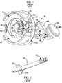
- FIG. 1 a perspective view of a brake assembly 10 is shown where opposing brake shoes 12 and 14 including brake linings 13 and 15 are mounted on a brake spider 22 by pivot pins 16 and 18 respectively at one end of the brake shoes 12 and 14.
- a return spring 20 urges the brake shoes 12 and 14 into rolling contact with an "S" cam 24 through rollers 26 and 28.
- the surface 32 of the "S” cam 24 contacts the roller 26 and causes the brake shoe 12 to steadily move toward the outer brake drum (not shown) until the brake lining rubs against the brake drum and the desired level of frictional braking is reached.
- the surface 33 of the "S" cam 24 contacts roller 28 and causes the brake shoe 14 to move outward toward the brake drum until the brake lining 15 touches the brake drum and the desired level of braking is reached.
- the "S" cam 24 is formed as part of, or attached to, the actuator shaft 34 which is attached to the actuator lever 36.
- the actuator lever 36 is connected to actuator 38 by actuator rod 40 and the prior art attachment clevis 51 in a manner that provides for the rotation of the actuator shaft 34 upon activation of actuator 38.
- the actuator shaft 34 is covered by a mounting tube 45 which is attached to the brake spider 22 at flange 43 by bolting.
- the mounting tube 45 is attached to bracket 44 which provides for the support of the actuator 38.
- the actuator 38 is commonly a pneumatic type where air pressure is supplied through inlet fitting 48 where it acts upon a diaphragm (not shown) thereby causing the actuator rod 40 to move outward from the actuator 38 causing the actuator lever 36 to move and rotate the actuator shaft 34 in the direction shown by arrow 46.
- the rotation of the actuator shaft 34 results in rotation of the "S" cam 24 shown by arrow 30 thereby actuating the brake shoes 12 and 14 and causing the brake linings 13 and 15 to move outward so as to contact the brake drum (not shown) and thereby frictionally apply a braking force to the brake drum and the attached wheel/tire (not shown).
- FIG. 2 a perspective view of the prior art actuator shaft 34 is shown.
- the "S" cam 24 is attached (or formed as one piece therewith) and at the other end, splines 50 are formed for nonrotational engagement with the actuator lever 36.
- Other methods of attachment of the actuator lever 36 to the actuator shaft 34 may be utilized such as welding or bolting.
- FIG. 3 shows the attachment clevis 51 and the actuator lever 36 in a normal orientation.
- a switch 56 has been mounted to a mounting mounting boss 55 formed as part of the attachment clevis 51 and positioned to face a side of the actuator lever 36 such that when the angle between the actuator rod 40 and the actuator lever 36 decreases to a given value, the actuation plunger 57 of the switch 56 contacts the actuator lever 36 as shown in FIG. 4.
- FIG. 4 illustrates the condition where the operator should be signaled that the brakes need attention usually replacement of the brake shoes or adjustment of the slack adjuster or adjustment of the attachment clevis 51.
- the attachment clevis 51 is threaded to the actuator rod 40 and secured with jam nut 53.
- the effective length of the actuator rod 40 can be increased or decreased by threading the attachment clevis 51 in or out thereby adjusting the relative position of the actuator lever 36 and the "S" cam 24.
- splines 52 are formed in the actuator lever 36 to mate with the splines 50 formed on the actuator shaft 34 thereby providing a nonrotational relationship between the actuator arm 36 and shaft 34.
- the attachment clevis 51 is joined to the actuator lever 36 by pin 54 which extends from one side of the attachment clevis 51 to the other through an attachment opening 66 formed in the lever 36.
- the attachment clevis 51 is joined to the actuator rod 40 by threads and secured by a jam nut 53.
- the switch 56 is of a common variety push to open (normally closed) or push to close (normally open) type of contact switch. Depression of actuation plunger 57 from a normal position causes an electrical circuit to become open or closed depending on the processing requirements of a processor unit 61. Leads 58 electrically connect the contacts of switch 56 to the processor unit 61 which then signals the vehicle operator and/or other processing unit when brake service is required.
- FIG. 4 illustrates such a condition where the lever 36 has been rotated by the actuator 38 as a result of axial outward travel of the actuator rod 40 causing the actuator lever 36 to rotate with the actuator shaft 34 in the direction of the arrow 46.
- the actuator lever 36 must rotate the actuator shaft 34 to such a degree that the switch 56 contacts the actuator lever 36 and the actuation plunger 57 of the switch 56 contacts a qualified surface 59 of the lever 36 thereby causing the vehicle operator to be warned of the worn brakes by action of the processor unit 51.
- FIG. 5 illustrates a prior art slack adjuster 60 which provides for adjustment of the angular orientation between the actuator lever 36' which has been supplemented by slack adjuster 60 and the actuator shaft 34.
- the adjustment mechanism 62 provides for rotation of splines 52 relative to the main body 63 of the actuator lever 36'.
- a worm gear rotates and engages and rotates the ring 65 in which the splines 52 are formed.
- the slack adjuster 60 can be adjusted when the switch 51 touches the actuator lever 36' thereby signaling to the processor unit 61 and to the operator that the brakes need servicing in the form of adjustment of the slack adjuster 60 or that the travel of the "S" cam 24 has reached the end of its travel, or that the brake linings 13 and 15 have worn to their service limit and require replacement.
- FIG. 6 is a bottom view of the attachment clevis 51 of FIGs. 3 and 4.
- the actuator rod 40 is threaded to engage threads cut into the clevis 51 where a jam nut 53 is used to secure the actuator rod in position and prevent rotation of the actuator rod 40 relative to the attachment clevis 51 until adjustment is required to return the actuator 38 into its normal range of travel.
- the mounting boss 55 provides a mounting surface for the switch 56 having an actuation plunger 57.
- Attachment holes 68 are formed in the attachment clevis 51 to provide an opening for passage of the pin 54.
Landscapes
- Engineering & Computer Science (AREA)
- General Engineering & Computer Science (AREA)
- Mechanical Engineering (AREA)
- Braking Arrangements (AREA)
Applications Claiming Priority (2)
| Application Number | Priority Date | Filing Date | Title |
|---|---|---|---|
| US54184095A | 1995-10-10 | 1995-10-10 | |
| US541840 | 1995-10-10 |
Publications (2)
| Publication Number | Publication Date |
|---|---|
| EP0768475A2 true EP0768475A2 (de) | 1997-04-16 |
| EP0768475A3 EP0768475A3 (de) | 1997-08-06 |
Family
ID=24161304
Family Applications (1)
| Application Number | Title | Priority Date | Filing Date |
|---|---|---|---|
| EP96115992A Withdrawn EP0768475A3 (de) | 1995-10-10 | 1996-10-05 | System zur Anzeige des Wartungszeitpunkts einer Bremse |
Country Status (1)
| Country | Link |
|---|---|
| EP (1) | EP0768475A3 (de) |
Cited By (2)
| Publication number | Priority date | Publication date | Assignee | Title |
|---|---|---|---|---|
| CN109798309A (zh) * | 2019-03-28 | 2019-05-24 | 山西峰润众盛汽车配件制造有限公司 | 一种制动间隙自动调整臂的报警装置 |
| CN109826888A (zh) * | 2019-03-28 | 2019-05-31 | 山西峰润众盛汽车配件制造有限公司 | 一种自调臂增加报警功能的装置 |
Family Cites Families (4)
| Publication number | Priority date | Publication date | Assignee | Title |
|---|---|---|---|---|
| US4800991A (en) * | 1985-08-19 | 1989-01-31 | Miller Nicholas A | Brake maintenance monitor |
| US5226509A (en) * | 1992-02-03 | 1993-07-13 | At-A-Glance, Inc. | At-a-glance brake travel indicator |
| US5253735A (en) * | 1992-09-28 | 1993-10-19 | Larson Reese G | Apparatus to sense and annunciate truck brake condition |
| US5320198A (en) * | 1993-07-22 | 1994-06-14 | Hoyt Gordon C | Air brake stroke length adjustment gauge |
-
1996
- 1996-10-05 EP EP96115992A patent/EP0768475A3/de not_active Withdrawn
Cited By (3)
| Publication number | Priority date | Publication date | Assignee | Title |
|---|---|---|---|---|
| CN109798309A (zh) * | 2019-03-28 | 2019-05-24 | 山西峰润众盛汽车配件制造有限公司 | 一种制动间隙自动调整臂的报警装置 |
| CN109826888A (zh) * | 2019-03-28 | 2019-05-31 | 山西峰润众盛汽车配件制造有限公司 | 一种自调臂增加报警功能的装置 |
| CN109826888B (zh) * | 2019-03-28 | 2024-06-14 | 南京善若网络科技有限公司 | 一种自调臂增加报警功能的装置 |
Also Published As
| Publication number | Publication date |
|---|---|
| EP0768475A3 (de) | 1997-08-06 |
Similar Documents
| Publication | Publication Date | Title |
|---|---|---|
| US5285190A (en) | Automatic slack adjuster with operation and adjustment monitor | |
| US7114596B2 (en) | Brake shoe proximity sensor | |
| US4945818A (en) | Stroke indicator for air operated diaphragm spring brakes | |
| CA1323586C (en) | Push-rod guide for air-operated diaphragm spring brakes | |
| EP1852628B1 (de) | Scheibenbremsenverschleißsteller | |
| US5572187A (en) | Air brake monitoring and safety system | |
| US5358075A (en) | Brake movement and adjustment monitoring device | |
| CA2520888C (en) | Method of monitoring the power spring of a spring brake actuator | |
| US8181752B2 (en) | Brake overstroke indication system | |
| EP1101971A1 (de) | Bremsbelagverschleissanzeiger | |
| US5632192A (en) | Spring brake actuator with indicator for fully released condition | |
| USH2026H1 (en) | Brake service signaling system | |
| US3605085A (en) | Brake lining wear detection means | |
| JP3953104B2 (ja) | 車両用ブレーキのブレーキシリンダ中の指示手段 | |
| US5358076A (en) | Indicator unit for an air brake system | |
| EP0768475A2 (de) | System zur Anzeige des Wartungszeitpunkts einer Bremse | |
| JP2009510356A (ja) | 軌道車両用の制動ユニット | |
| US4553643A (en) | Disc brake for trucks | |
| EP0337320B1 (de) | Mechanismus zum Entriegeln der automatischen Verstellvorrichtung in einer Trommelbremse | |
| EP0091151A1 (de) | Scheibenbremssattel für Schienenfahrzeug | |
| US4926980A (en) | Automatic brake adjusting mechanism | |
| US2852757A (en) | Brake assembly including a warning device | |
| JPH0152619B2 (de) | ||
| GB2333335A (en) | Brake assembly for a vehicle | |
| KR20050098321A (ko) | 라이닝 마모감지센서를 구비한 브레이크 장치 |
Legal Events
| Date | Code | Title | Description |
|---|---|---|---|
| PUAI | Public reference made under article 153(3) epc to a published international application that has entered the european phase |
Free format text: ORIGINAL CODE: 0009012 |
|
| AK | Designated contracting states |
Kind code of ref document: A2 Designated state(s): DE ES FR GB IT NL SE |
|
| PUAL | Search report despatched |
Free format text: ORIGINAL CODE: 0009013 |
|
| AK | Designated contracting states |
Kind code of ref document: A3 Designated state(s): DE ES FR GB IT NL SE |
|
| 17P | Request for examination filed |
Effective date: 19980205 |
|
| RAP1 | Party data changed (applicant data changed or rights of an application transferred) |
Owner name: DANA CORPORATION |
|
| 17Q | First examination report despatched |
Effective date: 19990809 |
|
| STAA | Information on the status of an ep patent application or granted ep patent |
Free format text: STATUS: THE APPLICATION IS DEEMED TO BE WITHDRAWN |
|
| 18D | Application deemed to be withdrawn |
Effective date: 19991221 |