EP0768645A1 - Methode zum oberflächenpolieren von magnetischen aufzeichnungsmedien und oberflächenpoliervorrichtung - Google Patents
Methode zum oberflächenpolieren von magnetischen aufzeichnungsmedien und oberflächenpoliervorrichtung Download PDFInfo
- Publication number
- EP0768645A1 EP0768645A1 EP96904275A EP96904275A EP0768645A1 EP 0768645 A1 EP0768645 A1 EP 0768645A1 EP 96904275 A EP96904275 A EP 96904275A EP 96904275 A EP96904275 A EP 96904275A EP 0768645 A1 EP0768645 A1 EP 0768645A1
- Authority
- EP
- European Patent Office
- Prior art keywords
- contact
- tape
- roll
- magnetic
- polishing
- Prior art date
- Legal status (The legal status is an assumption and is not a legal conclusion. Google has not performed a legal analysis and makes no representation as to the accuracy of the status listed.)
- Granted
Links
Images


Classifications
-
- G—PHYSICS
- G11—INFORMATION STORAGE
- G11B—INFORMATION STORAGE BASED ON RELATIVE MOVEMENT BETWEEN RECORD CARRIER AND TRANSDUCER
- G11B5/00—Recording by magnetisation or demagnetisation of a record carrier; Reproducing by magnetic means; Record carriers therefor
- G11B5/84—Processes or apparatus specially adapted for manufacturing record carriers
Definitions
- the present invention relates to a method for polishing a magnetic recording medium using a polishing tape and an apparatus therefor.
- a magnetic tape such as a video tape or an audio tape
- the following so-called coating type magnetic recording medium or a metal thin-film type magnetic recording medium are proposed. That is, according to the former, a magnetic coating material which is prepared in such a manner that a powdery magnetic material, a binder, and various additives are dispersed and kneaded together with an organic solvent is coated on a non-magnetic support member and then dried. According to the later, a magnetic layer is formed in such a manner that a metal magnetic material is directly coated on a non-magnetic support member by using a vacuum thin film forming technique.
- a recording/reproducing operation of an information signal with respect to each of these magnetic tapes is performed while the magnetic layer side of the magnetic tape is slidably moved on a magnetic head.
- the surface projections are sheared and broken by slidably moving between the magnetic head and the magnetic tape and interposed as a fine magnetic powder (to be referred to as an abrasion powder hereinafter) between the magnetic tape and the magnetic head.
- the abrasion powder interposed between the magnetic tape and the magnetic head causes dropouts, for example, causes image degradation, sound skipping, or the like, in the worst case, causes head clogging to make it impossible to record/reproduce data.
- a magnetic layer is formed on a non-magnetic support member, and then subjected to a surface process in which the magnetic layer surface is polished with a magnetic tape.
- a polishing apparatus for performing the surface process is shown in Fig. 1.
- the polishing apparatus 101 has a polishing tape 103 and a contact roll 102, having a diameter of about 30 mm, for pushing the polishing tape 103 against the a magnetic tape 104.
- the polishing tape 103 is wound on the contact roll 102 at an arbitrary holding angle to cause its polishing layer to face outside.
- the holding angle of the polishing tape 103 wound on the contact roll 102 is controlled in such a manner that the polishing tape 103 is looped between a pair of winding rolls 105a and 105b arranged parallel to each other near the contact roll 102.
- Guide rolls 106a and 106b are arranged on both the sides of the contact roll 102 on which the polishing tape 103 is wound, respectively.
- the guide rolls 106a and 106b are used to guide the magnetic tape 104 continuously travelling to a position where the magnetic tape 104 is brought into contact with the polishing tape 103 wound on the contact roll 102.
- a feeding roll and a take-up roll (not shown) are arranged for each of the polishing tape and the magnetic tape.
- the end portions of the polishing tape 103 are attached to the feeding roll and the take-up roll, respectively, and the end portions of the magnetic tape 104 are attached to the feeding roll and the take-up roll, respectively.
- the polishing tape travels in an X direction in Fig. 1, and, in contrast to this, the magnetic tape travels in a Y direction in Fig. 1. In this manner, the magnetic layer surface of the magnetic tape is polished by the polishing tape, and the surface projections on the magnetic layer surface is cut and removed.
- the polishing apparatus when the magnetic tape and the polishing tape are traveled in opposite directions, respectively, air is inserted between the magnetic tape and the polishing tape to form an air film, and the magnetic tape is in incomplete contact with the polishing tape. For this reason, the magnetic layer surface cannot be sufficiently polished by a single process.
- the surface process When a required high-quality magnetic tape is to be manufactured, the surface process must be performed a plurality of times to sufficiently polish the magnetic layer surface. Since the thickness of the air film formed between the magnetic tape and the polishing tape increases with a process speed, a process speed is limited to bring the magnetic tape and the polishing tape into sufficient contact with each other. Therefore, the process speed cannot be easily increased. For these reasons, a sufficiently long period of time is required to perform the surface polishing process, thereby preventing productivity of magnetic tapes from being improved.
- a surface polishing method of the present invention is characterized in that, when a magnetic layer surface of a magnetic tape is brought into contact with a polishing tape which is wound on a contact roll and travelled, and, in this state, the magnetic tape and the polishing tape are travelled in opposite directions to polish the magnetic layer surface of the magnetic tape, a curvature of the contact roll at a position where the magnetic tape is brought into contact with the polishing tape at first is set to be 0.1 to 10 mm.
- a surface polishing apparatus of the present invention includes a contact roll on which a polishing tape is wound and travelled, and travelling means which brings a magnetic layer surface of a magnetic tape into contact with the polishing tape to travel the polishing tape and the magnetic tape in opposite directions, and is characterized in that a curvature of the contact roll at a position where the magnetic tape is brought into contact with the polishing tape at first is set to be 0.1 to 10 mm.
- the curvature of the contact roll at the position where the magnetic tape is brought into contact with the polishing tape at first is set to be 0.1 to 10 mm, air is suppressed from being inserted between the polishing tape and the magnetic tape.
- the process speed is set to be relatively high, the polishing tape and the magnetic tape are always brought into preferable contact with each other, and an effective polishing operation can be achieved by a single process. Therefore, the process speed of surface polishing can be increased without repeating surface processing, and a high-quality magnetic recording medium can be manufactured at good productivity.
- first and second curves which have different curvature radii are continuously formed from the supply side of the magnetic tape, and the curvature radius of the first curve is set to be smaller than the curvature radius of the second curve.
- the curvature radius of the first curve is set to be 0.1 to 10 mm
- the curvature radius of the second curve is set to be 5 to 50 mm.
- the first and second curves may be formed to be a spiral curve whose curvature radius continuously is changed within the range of about 0.1 to 50 mm.
- a method of using a composite cylindrical roll having a shape obtained by combining a large-diameter roll and a small-diameter roll to each other may be used.
- a contact roll is constituted as a composite cylindrical roll having a sectional shape obtained by partially overlapping a large circle having a diameter of 10 to 100 mm and a small circle having a diameter of 0.2 to 20 mm.
- a magnetic tape and a polishing tape are arranged to be brought into contact with each other at first at a small circle portion.
- a method of arranging a plurality (2 to 5) of contact rolls each having a diameter of 0.2 to 20 mm, more preferably, 3 to 10 mm in such a manner the contact rolls are brought into contact with a polishing tape As the third method, a method of arranging a plurality (2 to 5) of contact rolls each having a diameter of 0.2 to 20 mm, more preferably, 3 to 10 mm in such a manner the contact rolls are brought into contact with a polishing tape.
- the contact rolls are preferably arranged on the same circumference, for example on the peripheral surface of the large-diameter roll.
- the surface roughness of the contact roll is preferably set to be 10 nm or less as a center line average height Ra, and the feeding speed of the polishing tape is preferably set to be 5 to 100 mm/min.
- Fig. 1 is a typical view showing the schematic arrangement of a conventional surface polishing apparatus.
- Fig. 2 is a typical view showing an arrangement of a surface polishing apparatus to which the present invention is applied.
- Fig. 3 is a typical view showing an example of a method of adjusting a contact state of a magnetic tape to a polishing tape.
- Fig. 4 is a typical view showing another example of a method of adjusting a contact state of a magnetic tape to a polishing tape.
- Fig. 5 is a typical view showing an example of a contact roll whose curvature is continuously changed.
- Fig. 6 is a typical view showing another example of the surface polishing apparatus to which the present invention is applied.
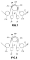
- Fig. 7 is a typical view showing still another example of the surface polishing apparatus to which the present invention is applied.
- Fig. 8 is a typical view showing another shape of a support member for supporting a plurality of contact rolls.
- Embodiments of a method and apparatus, for polishing the surface of a magnetic recording medium, to which the present invention is applied, will be described below.
- the curvature of a contact roll is continuously changed.
- a magnetic recording medium surface polishing apparatus 1 is constituted as follows. That is, as shown in Fig. 2, a magnetic layer formation surface of a magnetic tape 2 is brought into contact with a contact blade 3 corresponding to a contact roll through a wrapping tape 4, and the magnetic tape 2 and the wrapping tape 4 travel in a state wherein the wrapping tape 4 is in contact with the magnetic layer formation surface of the magnetic tape 2.
- the wrapping tape 4 is formed such that a polishing agent layer containing a polishing agent is formed on a belt-like non-magnetic support member 2.
- a polishing agent contained in the polishing agent layer a generally used polishing agent of, e.g., #2,000 to #3,000 may be properly used.
- a convey path (X direction in Fig. 2) in which the wrapping tape 4 is sequentially supplied from a roll 5a, taken up by a roll 5b, and sequentially conveyed to the contact blade 2 is constituted.
- the contact blade 3 is used to slidably contact the wrapping tape 4 on the outer peripheral surface of the magnetic tape 2 on which the magnetic layer is formed.
- the contact blade 3 in this embodiment is of a fixed type, and is formed in such a manner that curvature radii R of the outer peripheral surface are different from each other.
- a first curve 3a and a second curve 3b whose curvature radii R are different from each other are continuously formed from the supply side of the non-magnetic support member 2 into the contact blade 3.
- a convey path (Y direction in Fig. 1) in which the magnetic tape 2 is sequentially conveyed to the contact roll 3 is formed through guide rolls 6a and 6b. Therefore, the curvature radius R1 of the first curve 3a is formed to be smaller than the curvature radius R2 of the second curve 3b in such a manner that the magnetic tape 2 is brought into contact with the first curve 3a having a small curvature radius R when the magnetic tape 2 is supplied to the contact blade 3.
- the contact blade 3 is preferably formed such that the curvature radius R1 of the first curve 3a is set to be about 0.1 to 10 mm, and the curvature radius R2 of the second curve 3b is set to be about 5 to 50 mm.
- curvature radius R2 of the second curve 3b is smaller than 5 mm, a polishing collection effect is short, and surface projections and polishing powder are left on the magnetic layer surface to cause a dropout error (surface defects of the magnetic tape). If the curvature radius R2 of the second curve 3b exceeds 50 mm, scratch flaws may be formed in the magnetic layer surface.
- the curvature radius R1 of the first curve 3a exceeds 10 mm, a polishing effect is short, and remaining surface projections cause a dropout error.
- the reasons why the lower limit of the curvature radius R1 of the first curve 3a is set to be 0.1 mm is not only that the contact blade 3 cannot be easily manufactured at a high processing precision, but also that the supply angle of the magnetic tape 2 cannot be easily set.
- a holding angle (contact surface) of the magnetic tape 2 with respect to the contact blade 3 can be adjusted by various mechanisms.
- the angle of the contact blade 3 is made variable, and the guide rolls 6a and 6b are made movable on the circumference of the contact blade 3, thereby making it possible to adjust the holding angle.
- the orientation of the contact blade 3 is adjusted in the direction of an arrow D, and the guide rolls 6a and 6b are moved in the directions of an arrow A and an arrow B on a concentric circle C, thereby adjusting a contact start position between the magnetic tape 2 and the wrapping tape 4 and a contact area of the magnetic tape 2 on the contact blade 3.
- the contact blade 3 and the rolls 5a and 5b are fixed to a fixing plate 7 to form a unit, and a pressing amount of the fixing plate 7 is changed to adjust the holding angle and the contact area.
- the magnetic recording medium surface polishing apparatus 1 is constituted in such a manner that the first curve 3a having a small curvature radius R is formed on the supply side of the magnetic tape 2 into the contact blade 3. For this reason, the magnetic tape 2 is fed to the position of the second curve 3b having a large curvature radius R in a state wherein formation of an air film is reliably suppressed. Therefore, even if one contact blade having the above arrangement is used, formation of an air film is suppressed. In addition, the speed of the polishing process is increased, thereby preventing a dropout error or a scratch flaw.
- Raw materials of the following composition were weighed to prepare a magnetic coating material. More specifically, a magnetic powder was kneaded with a binder to prepare the magnetic coating material, and the resultant magnetic coating material was coated on a base film serving as a non-magnetic support member. The resultant structure was subjected to a calendar process (by surface processing apparatus) to form a magnetic layer.
- Co- ⁇ -Fe 2 O 3 100 parts by weight binder resin; 20 parts by weight polyester polyurethane resin nitrocellulose polishing agent; Al 2 O 3 3 parts by weight additive; carbon powder 2 parts by weight lubricant; butyl stearate 1 parts by weight solvent; methyl ethyl ketone 100 parts by weight toluene 100 parts by weight cyclohexanone 50 parts by weight
- the magnetic coating material prepared as described above was formed as a magnetic layer on a base film having a thickness of 14 ⁇ m.
- the magnetic raw film on which the magnetic layer was formed was cut into tapes each having a width of 1/2 inch, the polishing process of the magnetic layer surface was formed by using the magnetic recording medium surface polishing apparatus 1 having the above arrangement.
- the cutting step of cutting the film into a predetermined size according to a tape width and the step of testing products were sequentially performed.
- a contact blade having the curvature radius R1 of the contact blade 3 and the curvature radius R2 of the second curve 3b which were set to be values shown in Table 2.
- contact blades respectively having diameters of ⁇ 30 mm and ⁇ 6 mm were used.
- the contact roll having a diameter of ⁇ 30 mm was used as the contact roll 102 serving as the cylindrical roll described in the prior art.
- GC-6000 (trade name) available from Nihon Microcoating Co Ltd., was used.
- the traveling speed of the magnetic tape 2 on which the magnetic layer was formed was changed to 200 m/min, 400 m/min, or 600 m/min.
- the magnetic tape 2 which was subjected to the polishing process under the various conditions described above was visually observed to detect the presence/absence of scratch flaws.
- the magnetic tape 2 was loaded on a cassette tape deck, and the situation of occurrence of dropout errors were evaluated using a VHS type VTR (available from Matsushita Electric Industrial Co., Ltd.; trade name: AG-6200) and a dropout counter (available from Shibasoku).
- VHS type VTR available from Matsushita Electric Industrial Co., Ltd.; trade name: AG-6200
- a dropout counter available from Shibasoku
- Table 1 shows evaluation results obtained when the curvature radius R2 of the second curve 3b was set to be 15 mm or 60 mm, and the curvature radius R1 of the first curve 3a was variously changed.
- Table 2 shows evaluation results obtained when the curvature radius R1 of the first curve 3a was fixed to 3 mm, and the curvature radius R2 of the second curve 3b was variously changed.
- Tables 1 and 2 The situations of occurrence of dropout errors in Tables 1 and 2 was evaluated with reference to the situation of occurrence of dropout error obtained when a cylindrical roll having a diameter of ⁇ 30 mm.
- ⁇ denotes a case wherein the number of dropout errors is smaller than that in the case of a magnetic tape subjected to a polishing process by a conventional method
- ⁇ denotes a case wherein the number of dropout errors is equal to that in the case of a magnetic tape subjected to a polishing process by a conventional method
- "X" denotes a case wherein the number of dropout errors is larger than that in the case of a magnetic tape subjected to a polishing process by a conventional method.
- the first curve 3a and the second curve 3b of the contact blade 3 having different curvature radii R are continuously formed from the supply side of the non-magnetic support member 2.
- the contact blade 3 in which the curvature radius of the first curve is smaller than the curvature radius of the second curve is used, excellent results with respect to dropout errors and scratch flaws can be obtained compared with Comparative Example 1-1 and Comparative Example 1-4.
- the polishing process was preferably performed when the speed of the polishing process was 200 m/min. However, when the speed was increased to 400 m/min and 600 m/min, no scratch flaws were observed, but dropout errors were observed.
- Comparative Example 1-5 in which the curvature radius of the second curve 3b was 5 mm, no scratch flows were observed, but dropout errors were observed.
- Comparative Example 1-6 in which the curvature radius of the second curve 3b exceeded 50 mm, when the speed of the polishing process was increased, no dropout errors were observed, but scratch flaws were observed.
- the efficient polishing process can be performed even if the speed of the polishing process is increased to 600 m/min, and a high-quality magnetic recording medium is manufactured.
- the curvature may be set to be gradually changed.
- a contact blade in which the curvature is gradually changed is shown in Fig. 5.
- the curvature radius (R3, R4, R5, R6, and R7) of a contact blade 13 is continuously changed within the range of about 0.1 to 50 mm. That is, the contact blade 13 is formed as a spiral curve.
- the contact blade 13 is constituted such that the curvature radius is gradually increased within the range of 0.1 to 50 mm, from a supply side S1 of a magnetic tape 2 to a feeding side S2 of the magnetic tape 2 (R3 ⁇ R4 ⁇ R5 ⁇ R6 ⁇ R7).
- the remaining arrangement of the surface polishing apparatus 11 is the same as that in the first embodiment described above.
- the magnetic tape 2 is gradually traveled from the supply side S1 (curve 13a portion having a small curvature radius) of the contact blade 13, and is fed to the feeding side S2 of a curve 13b having a large curvature radius R in a state wherein formation of an air film is reliably suppressed. Therefore, formation of an air film can be suppressed, degradation of the magnetic tape quality caused by an increase in speed of the polishing process does not occur.
- the curvature radius of one contact blade 3 is changed depending on position (R3 ⁇ R4 ⁇ R5 ⁇ R6 ⁇ R7), the following advantages can be obtained. That is, a countermeasure to an air film or the like can be effectively performed by adjusting the supply angle of the magnetic tape 2 or the like, or the depth (amount) of the polishing process can be properly adjusted.
- a polishing tape 22 is traveled in a direction opposing the direction of a belt-like magnetic tape 21 which continuously travels while the polishing tape 22 is in contact with the magnetic tape 21, thereby polishing the magnetic tape 21.
- the polishing apparatus has a contact roll 23 for pressing the polishing tape 22 to the magnetic tape 21.
- the polishing tape 22 is formed such that a polishing agent layer containing a polishing agent is formed on a belt-like support member.
- a polishing agent contained in the polishing agent layer a generally used polishing agent of, e.g., #2,000 to #10,000 may be properly used.
- this polishing apparatus especially, a composite cylindrical roll having a sectional shape in which a first circle having a diameter of 10 to 100 mm and a second circle having a diameter of 0.2 to 20 mm partially overlap. More specifically, this composite cylindrical roll has an appearance in which the curved surface of the small-diameter cylindrical roll 23b having the second circle as a section partially overlaps the curved surface of the large-diameter cylindrical roll 23a having the first circle as a section.
- This contact roll is arranged such that the small-diameter cylindrical roll faces the supply side of the magnetic tape.
- the polishing tape 22 is wound on the contact roll 23 at an arbitrary holding angle such that the polishing agent layer faces outside.
- the holding angle of the polishing tape 22 wound on the contact roll 23 is regulated such that the polishing tape 22 is looped between a pair of winding rolls 24 and 25 parallelly arranged near the contact roll 23.
- Guide rolls 26 and 27 are arranged on both the sides of the contact roll 23 on which the polishing tape 22 is wound.
- the guide rolls 26 and 27 are arranged to guide the magnetic tape 21 which continuously travels to a position where the magnetic tape 21 is brought into contact with the polishing tape 22 wound on the contact roll 23.
- a feeding roll and a take-up roll (not shown) are arranged for each of the polishing tape and the magnetic tape.
- the end portions of the polishing tape 22 are attached to the feeding roll and the take-up roll, respectively, and the end portions of the a magnetic tape 21 are attached to the feeding roll and the take-up roll, respectively. In this manner, the polishing tape 22 and the magnetic tape 21 are continuously traveled in opposite directions, respectively.
- the feeding roll and the take-up roll for the polishing tape and the magnetic tape are rotatably driven.
- the polishing tape 22 travels in an X direction in Fig. 6, and, in contrast to this, the magnetic tape 21 travels in a Y direction in Fig. 6. In this manner, the magnetic layer surface of the magnetic tape slidably contact the polishing tape.
- the contact roll is an ordinary cylindrical roll
- the polishing tape and the magnetic tape are continuously traveled as described above, air is inserted between the tapes to form an air film.
- the contact roll 23 is the composite cylindrical roll having an appearance in which the curved surface of the small-diameter cylindrical roll 23b partially overlaps the curved surface of the large-diameter cylindrical roll 23a.
- the curved surface of the small-diameter cylindrical roll 23b functions to push air inserted between the polishing tape 22 and the magnetic tape 21 out of therebetween.
- a processing speed is set to be relatively high, the polishing tape 22 is in preferable contact with the magnetic tape 21, effective polishing can be obtained by performing the polishing process once. Therefore, the processing speed can be made high, and the polishing process need not be repeated. As a result, high-quality magnetic recording media can be manufactured at a high productivity.
- the diameter of the large-diameter cylindrical roll 23a must be 10 to 100 mm. If the diameter of the large-diameter cylindrical roll 23a is smaller than 10 mm, a lack of polishing effect occurs, surface projections are left on the magnetic layer surface to cause dropout. If the diameter of the large-diameter cylindrical roll 23a exceeds 100 mm, scratch flaws may be formed in the magnetic layer surface.
- the diameter of the large-diameter cylindrical roll 23a is preferably set within the range of 20 to 100 mm.
- the diameter of the small-diameter cylindrical roll 23b must be 0.2 to 20 mm. If the diameter of the small-diameter cylindrical roll 23b exceeds 20 mm, a lack of polishing effect occurs, surface projections left on the magnetic layer surface cause dropout.
- the reason why the lower limit of the diameter is set to be 0.2 mm is that a cylindrical roll having a diameter lower than 0.2 mm cannot be easily manufactured due to its processing precision.
- the diameter of the small-diameter cylindrical roll is preferably set within the range of 3 to 10 mm.
- a contact roll of the polishing apparatus As a contact roll of the polishing apparatus, a composite cylindrical roll having a small-diameter cylindrical roll and a large-diameter cylindrical roll whose diameters were values shown in Table 3 or Table 4 was used. As a comparative example, a cylindrical roll having a diameter of 30 mm and a cylindrical roll having a diameter of 6 mm were used.
- Table 3 shows evaluation results obtained when the diameter of the large-diameter cylindrical roll was set to be 30 mm or 60 mm, and the diameter of the small-diameter cylindrical roll was variously changed.
- Table 4 shows evaluation results obtained when the diameter of the small-diameter cylindrical roll was fixed to 6 mm, and the large-diameter cylindrical roll was variously changed.
- Example 3 As shown in Table 3, in a magnetic tape of Example 2-1 in which the surface process is performed directly using the large-diameter cylindrical roll having a diameter of 30 mm as a contact roll was traveled on a VTR. The dropout errors occurs frequently with an increase in processing speed of the surface process. In the magnetic tape of Example 3-1 in which the surface process is performed directly using a small-diameter cylindrical roll having a diameter of 6 mm as a contact roll, the frequency of occurrence of dropout errors is higher than that in Example 2-1, and scratch flaws are visually observed.
- the diameter of the small-diameter cylindrical roll is set within the range of 3 to 20 mm, and occurrence of dropouts is suppressed.
- the diameter of the small-diameter cylindrical roll is set to be 3 to 10 mm, even if the processing speed of the surface process is increased up to 600 m/min, the number of times of occurrence of dropouts is suppressed to a sufficiently small value.
- Example 3-2 to Example 3-10 In systems (Example 3-2 to Example 3-10) in which the diameter of the small-diameter cylindrical roll is fixed to 6 mm and the diameter of the large-diameter cylindrical roll is variously changed, the diameter of the large-diameter cylindrical roll is set within the range of 10 to 100 mm, and occurrence of dropouts is suppressed. In particular, when the diameter of the large-diameter cylindrical roll is set to be 20 to 100 mm, even if the processing speed of the surface process is increased up to 600 m/min, the number of times of occurrence of dropouts is suppressed to a sufficiently small value.
- the effective surface process can be performed even if the processing speed is set to be 600 m/min, and a high-quality magnetic recording medium is manufactured.
- a plurality (three in Fig. 7) contact rolls 33a, 33b, and 33c are arranged at the halfway portion of a path on which a magnetic tape 31 serving as an object to be processed is traveled from the feeding side to the take-up side.
- the contact rolls 33a, 33b, and 33c are arranged at predetermined intervals on the peripheral surface of a contact roll support member having a diameter larger than that of each of the contact rolls 33a, 33b, and 33c.
- the contact rolls 33a, 33b, and 33c may be fixed on the peripheral surface of the contact roll support member 34, or may be rotatably attached to the contact roll support member 34.
- the shape of the contact roll support member 34 an arbitrary shape may be employed.
- the contact roll support member 34 may have a circular section, or as shown in Fig. 8, a pentagonal section.
- a polishing tape 32 fed from a feeding roll 35 which can be rotated clockwise is sequentially supplied between the contact rolls 33a, 33b, and 33c and the magnetic tape 1 which is traveled along the peripheral surfaces of the contact rolls 33a, 33b, and 33c, and the polishing tape 32 is brought into contact with the magnetic tape 31 to perform a surface process to the magnetic tape 31.
- the magnetic tape 31 is traveled along the peripheral surfaces of the contact rolls 33a, 33b, and 33c, and the polishing tape 32 is sequentially traveled from the feeding roll 35 to a take-up roll 36 which can be rotated clockwise, thereby performing a surface process to the magnetic tape 31.
- An effect of a reduction in dropout can be obtained.
- the diameter of each of the contact rolls 33a, 33b, and 33c is set to be 0.2 mm or more (preferably, 3 mm or more, more preferably, 6 mm or more) and 20 mm or less, and the surface roughness of the contact rolls 33a, 33b, and 33c is 10 nm or less (preferably, 5 nm or less) as a center line average height Ra, the number of contact rolls is set to be 2 or more and 5 or less.
- an insertion amount of air film between the magnetic tape 31 and the polishing tape 32 is suppressed to the minimum value, and a preferable contact state can be obtained. Therefore, a preferably effect of a reduction in dropout can be obtained, and the quality of the magnetic tape can be improved by improvement on surface properties. At the same time, cost can be reduced by improvement on surface process efficiency.
- Guide rolls 37a and 37b having diameters larger than those of the contact rolls 33a, 33b, and 33c are arranged at the halfway portion of the path on which a magnetic tape 31 is traveled from the feeding side to the contact roll 33a and at the halfway portion of the path on which a magnetic tape 31 is traveled from the contact roll 33c to the take-up side, respectively to give proper tension to the magnetic tape 31 which is traveled from the feeding side to the take-up side and to make it possible to smoothly travel the magnetic tape 31.
- Each of the contact rolls 33a, 33b, and 33c, the contact roll support member 34, and the guide rolls 37a and 37b is a cylindrical member having a width which is almost equal to that of the magnetic tape 31.
- a metal, a plastic, or the like may be used as the material of these members.
- raw materials having the following composition were kneaded with a continuous kneader, dispersed using a sand mill, and filtered with a filter having an average aperture of 2 ⁇ m, thereby preparing a magnetic coating material.
- the raw materials having the above composition were mixed with each other for 48 hours and then filtered with a filter having an average aperture of 1.5 ⁇ m to prepare a coating material for a back coating layer.
- non-magnetic powder carbon black 100 parts by weight (available from Colombian Carbon, trade name: RAVEN-1255)
- binder polyurethane resin (available from Toyobo Co., Ltd., trade name: UR-8300) 50 parts by weight solvent: methyl ethyl ketone 220 parts by weight methyl isobutyl ketone 220 parts by weight toluene 220 parts by weight
- a hardening agent (Colonate L) was added to the coating material for a back coating layer prepared as described above.
- the magnetic coating material was coated on the other surface of the polyethylene terephthalate film to have a thickness of 2.0 ⁇ m, and subjected to a calendar process and a hardening process.
- the magnetic film was cut to have a width of 8 mm, thereby forming a tape.
- the surface of the magnetic tapes after the surface process was observed with an optical microscope to evaluate the surface roughnesses in three stages, i.e., A, B, and C.
- Dropouts were measured using an 8-mm VTR deck for 20 minutes under a condition of -16 dB/3 ⁇ s, and an average value was used. In this case, if the number of dropouts is equal or smaller than 20, a corresponding sample tape can be preferably used.
- the feeding speed of the polishing tape is 5 mm/min or less, catching capability of catching objects which causes dropouts by clogging of the polishing tape is insufficient, an effect of a reduction in dropout is degraded. If the feeding speed is 100 mm/min or more, fine flaws formed on the magnetic tape surface are detected.
Landscapes
- Manufacturing Of Magnetic Record Carriers (AREA)
- Finish Polishing, Edge Sharpening, And Grinding By Specific Grinding Devices (AREA)
Applications Claiming Priority (16)
| Application Number | Priority Date | Filing Date | Title |
|---|---|---|---|
| JP40561/95 | 1995-02-28 | ||
| JP4056195 | 1995-02-28 | ||
| JP4056195 | 1995-02-28 | ||
| JP8299395 | 1995-04-07 | ||
| JP82993/95 | 1995-04-07 | ||
| JP8299395 | 1995-04-07 | ||
| JP217924/95 | 1995-08-25 | ||
| JP21792495 | 1995-08-25 | ||
| JP21792495 | 1995-08-25 | ||
| JP25426395 | 1995-09-29 | ||
| JP25426395 | 1995-09-29 | ||
| JP254263/95 | 1995-09-29 | ||
| JP27940895 | 1995-10-26 | ||
| JP279408/95 | 1995-10-26 | ||
| JP27940895 | 1995-10-26 | ||
| PCT/JP1996/000470 WO1996027188A1 (en) | 1995-02-28 | 1996-02-28 | Surface polishing method for magnetic recording medium and surface polishing apparatus |
Publications (3)
| Publication Number | Publication Date |
|---|---|
| EP0768645A1 true EP0768645A1 (de) | 1997-04-16 |
| EP0768645A4 EP0768645A4 (de) | 1997-12-03 |
| EP0768645B1 EP0768645B1 (de) | 2003-08-06 |
Family
ID=27522090
Family Applications (1)
| Application Number | Title | Priority Date | Filing Date |
|---|---|---|---|
| EP96904275A Expired - Lifetime EP0768645B1 (de) | 1995-02-28 | 1996-02-28 | Methode zum oberflächenpolieren von magnetischen aufzeichnungsmedien und oberflächenpoliervorrichtung |
Country Status (3)
| Country | Link |
|---|---|
| US (1) | US5876270A (de) |
| EP (1) | EP0768645B1 (de) |
| WO (1) | WO1996027188A1 (de) |
Families Citing this family (4)
| Publication number | Priority date | Publication date | Assignee | Title |
|---|---|---|---|---|
| JP4149679B2 (ja) * | 2001-02-28 | 2008-09-10 | 富士フイルム株式会社 | 磁気記録媒体の製造方法 |
| US6796884B1 (en) | 2002-02-08 | 2004-09-28 | Imation Corp. | Abrasivity control of magnetic media using burnishing techniques |
| US7597607B2 (en) * | 2006-04-12 | 2009-10-06 | Imation Corp. | Magnetic recording tape edge processing |
| JP6737473B2 (ja) * | 2018-03-29 | 2020-08-12 | Necプラットフォームズ株式会社 | 磁気テープ装置及び磁気テープの検査方法 |
Family Cites Families (5)
| Publication number | Priority date | Publication date | Assignee | Title |
|---|---|---|---|---|
| DE3103874A1 (de) * | 1981-02-05 | 1982-09-09 | Basf Ag, 6700 Ludwigshafen | Verfahren und vorrichtung zum bearbeiten der oberflaeche magnetischer aufzeichnungstraeger |
| JPS6362656A (ja) * | 1986-09-02 | 1988-03-18 | Fuji Photo Film Co Ltd | 磁気記録媒体の製造方法 |
| JPH081698B2 (ja) * | 1988-04-19 | 1996-01-10 | 富士写真フイルム株式会社 | 磁気記録媒体の製法 |
| JPH03178034A (ja) * | 1989-12-07 | 1991-08-02 | Sony Corp | 磁気記録媒体の製造方法 |
| US5669804A (en) * | 1994-10-25 | 1997-09-23 | Sony Corporation | Magnetic tape surface treatment method and apparatus |
-
1996
- 1996-02-28 WO PCT/JP1996/000470 patent/WO1996027188A1/ja not_active Ceased
- 1996-02-28 US US08/727,626 patent/US5876270A/en not_active Expired - Fee Related
- 1996-02-28 EP EP96904275A patent/EP0768645B1/de not_active Expired - Lifetime
Also Published As
| Publication number | Publication date |
|---|---|
| EP0768645B1 (de) | 2003-08-06 |
| EP0768645A4 (de) | 1997-12-03 |
| WO1996027188A1 (en) | 1996-09-06 |
| US5876270A (en) | 1999-03-02 |
Similar Documents
| Publication | Publication Date | Title |
|---|---|---|
| JP6689222B2 (ja) | 磁気テープ | |
| JP6689223B2 (ja) | 磁気テープ | |
| EP1742205B1 (de) | Magnetisches Aufzeichnungsmedium | |
| JP6465823B2 (ja) | 磁気テープおよびその製造方法 | |
| JP2005228377A (ja) | 磁気テープ | |
| JP2003022520A (ja) | 磁気テープ | |
| US4922675A (en) | Abrasive tape | |
| US5827599A (en) | Magnetic recording tape having a backcoat and specified edge profile | |
| US5036629A (en) | Method for preparing a magnetic recording medium | |
| EP0768645B1 (de) | Methode zum oberflächenpolieren von magnetischen aufzeichnungsmedien und oberflächenpoliervorrichtung | |
| EP0618580B1 (de) | Magnetbandkassette mit reduzierter elektrostatischen Aufladung | |
| EP0530733A1 (de) | Magnetisches Aufzeichnungsmedium | |
| US6723415B2 (en) | Magnetic recording medium | |
| US20020051877A1 (en) | Magnetic tape | |
| JP2002163816A (ja) | 磁気テープ | |
| US5073439A (en) | Magnetic recording medium comprising a vinyl chloride based resin group containing an epoxy group or a polar or both and further a polyurethane resin containing three hydroxyl groups and one polar group | |
| US7045228B2 (en) | Magnetic tape | |
| JPWO1996027188A1 (ja) | 磁気記録媒体の表面研磨方法及び表面研磨装置 | |
| US5547510A (en) | Coating apparatus | |
| US6120877A (en) | Magnetic recording medium | |
| JP2002133648A (ja) | 磁気テープ | |
| JP4654757B2 (ja) | 磁気記録媒体 | |
| JP3533679B2 (ja) | 磁気記録媒体の製造方法 | |
| JP2587315B2 (ja) | 磁気記録媒体の製造方法 | |
| JP4683403B2 (ja) | カートリッジ式クリーニングテープ |
Legal Events
| Date | Code | Title | Description |
|---|---|---|---|
| PUAI | Public reference made under article 153(3) epc to a published international application that has entered the european phase |
Free format text: ORIGINAL CODE: 0009012 |
|
| 17P | Request for examination filed |
Effective date: 19970214 |
|
| AK | Designated contracting states |
Kind code of ref document: A1 Designated state(s): FR |
|
| A4 | Supplementary search report drawn up and despatched | ||
| AK | Designated contracting states |
Kind code of ref document: A4 Designated state(s): FR |
|
| 17Q | First examination report despatched |
Effective date: 20020523 |
|
| GRAH | Despatch of communication of intention to grant a patent |
Free format text: ORIGINAL CODE: EPIDOS IGRA |
|
| GRAH | Despatch of communication of intention to grant a patent |
Free format text: ORIGINAL CODE: EPIDOS IGRA |
|
| GRAA | (expected) grant |
Free format text: ORIGINAL CODE: 0009210 |
|
| AK | Designated contracting states |
Designated state(s): FR |
|
| ET | Fr: translation filed | ||
| PLBE | No opposition filed within time limit |
Free format text: ORIGINAL CODE: 0009261 |
|
| STAA | Information on the status of an ep patent application or granted ep patent |
Free format text: STATUS: NO OPPOSITION FILED WITHIN TIME LIMIT |
|
| 26N | No opposition filed |
Effective date: 20040507 |
|
| PGFP | Annual fee paid to national office [announced via postgrant information from national office to epo] |
Ref country code: FR Payment date: 20090213 Year of fee payment: 14 |
|
| REG | Reference to a national code |
Ref country code: FR Ref legal event code: ST Effective date: 20101029 |
|
| PG25 | Lapsed in a contracting state [announced via postgrant information from national office to epo] |
Ref country code: FR Free format text: LAPSE BECAUSE OF NON-PAYMENT OF DUE FEES Effective date: 20100301 |