EP0768648B1 - Milieu d'enregistrement optique d'information - Google Patents
Milieu d'enregistrement optique d'information Download PDFInfo
- Publication number
- EP0768648B1 EP0768648B1 EP96116142A EP96116142A EP0768648B1 EP 0768648 B1 EP0768648 B1 EP 0768648B1 EP 96116142 A EP96116142 A EP 96116142A EP 96116142 A EP96116142 A EP 96116142A EP 0768648 B1 EP0768648 B1 EP 0768648B1
- Authority
- EP
- European Patent Office
- Prior art keywords
- read
- zone
- data
- grooves
- disk
- Prior art date
- Legal status (The legal status is an assumption and is not a legal conclusion. Google has not performed a legal analysis and makes no representation as to the accuracy of the status listed.)
- Expired - Lifetime
Links
Images




Classifications
-
- G—PHYSICS
- G11—INFORMATION STORAGE
- G11B—INFORMATION STORAGE BASED ON RELATIVE MOVEMENT BETWEEN RECORD CARRIER AND TRANSDUCER
- G11B7/00—Recording or reproducing by optical means, e.g. recording using a thermal beam of optical radiation by modifying optical properties or the physical structure, reproducing using an optical beam at lower power by sensing optical properties; Record carriers therefor
- G11B7/24—Record carriers characterised by shape, structure or physical properties, or by the selection of the material
- G11B7/2407—Tracks or pits; Shape, structure or physical properties thereof
- G11B7/24073—Tracks
- G11B7/24079—Width or depth
-
- G—PHYSICS
- G11—INFORMATION STORAGE
- G11B—INFORMATION STORAGE BASED ON RELATIVE MOVEMENT BETWEEN RECORD CARRIER AND TRANSDUCER
- G11B7/00—Recording or reproducing by optical means, e.g. recording using a thermal beam of optical radiation by modifying optical properties or the physical structure, reproducing using an optical beam at lower power by sensing optical properties; Record carriers therefor
- G11B7/007—Arrangement of the information on the record carrier, e.g. form of tracks, actual track shape, e.g. wobbled, or cross-section, e.g. v-shaped; Sequential information structures, e.g. sectoring or header formats within a track
- G11B7/00718—Groove and land recording, i.e. user data recorded both in the grooves and on the lands
-
- G—PHYSICS
- G11—INFORMATION STORAGE
- G11B—INFORMATION STORAGE BASED ON RELATIVE MOVEMENT BETWEEN RECORD CARRIER AND TRANSDUCER
- G11B7/00—Recording or reproducing by optical means, e.g. recording using a thermal beam of optical radiation by modifying optical properties or the physical structure, reproducing using an optical beam at lower power by sensing optical properties; Record carriers therefor
- G11B7/007—Arrangement of the information on the record carrier, e.g. form of tracks, actual track shape, e.g. wobbled, or cross-section, e.g. v-shaped; Sequential information structures, e.g. sectoring or header formats within a track
- G11B7/0079—Zoned data area, e.g. having different data structures or formats for the user data within data layer, Zone Constant Linear Velocity [ZCLV], Zone Constant Angular Velocity [ZCAV], carriers with RAM and ROM areas
-
- G—PHYSICS
- G11—INFORMATION STORAGE
- G11B—INFORMATION STORAGE BASED ON RELATIVE MOVEMENT BETWEEN RECORD CARRIER AND TRANSDUCER
- G11B7/00—Recording or reproducing by optical means, e.g. recording using a thermal beam of optical radiation by modifying optical properties or the physical structure, reproducing using an optical beam at lower power by sensing optical properties; Record carriers therefor
- G11B7/007—Arrangement of the information on the record carrier, e.g. form of tracks, actual track shape, e.g. wobbled, or cross-section, e.g. v-shaped; Sequential information structures, e.g. sectoring or header formats within a track
- G11B7/013—Arrangement of the information on the record carrier, e.g. form of tracks, actual track shape, e.g. wobbled, or cross-section, e.g. v-shaped; Sequential information structures, e.g. sectoring or header formats within a track for discrete information, i.e. where each information unit is stored in a distinct discrete location, e.g. digital information formats within a data block or sector
-
- G—PHYSICS
- G11—INFORMATION STORAGE
- G11B—INFORMATION STORAGE BASED ON RELATIVE MOVEMENT BETWEEN RECORD CARRIER AND TRANSDUCER
- G11B20/00—Signal processing not specific to the method of recording or reproducing; Circuits therefor
- G11B20/10—Digital recording or reproducing
- G11B20/12—Formatting, e.g. arrangement of data block or words on the record carriers
- G11B20/1217—Formatting, e.g. arrangement of data block or words on the record carriers on discs
- G11B2020/1259—Formatting, e.g. arrangement of data block or words on the record carriers on discs with ROM/RAM areas
-
- G—PHYSICS
- G11—INFORMATION STORAGE
- G11B—INFORMATION STORAGE BASED ON RELATIVE MOVEMENT BETWEEN RECORD CARRIER AND TRANSDUCER
- G11B7/00—Recording or reproducing by optical means, e.g. recording using a thermal beam of optical radiation by modifying optical properties or the physical structure, reproducing using an optical beam at lower power by sensing optical properties; Record carriers therefor
- G11B7/007—Arrangement of the information on the record carrier, e.g. form of tracks, actual track shape, e.g. wobbled, or cross-section, e.g. v-shaped; Sequential information structures, e.g. sectoring or header formats within a track
- G11B7/00745—Sectoring or header formats within a track
-
- G—PHYSICS
- G11—INFORMATION STORAGE
- G11B—INFORMATION STORAGE BASED ON RELATIVE MOVEMENT BETWEEN RECORD CARRIER AND TRANSDUCER
- G11B7/00—Recording or reproducing by optical means, e.g. recording using a thermal beam of optical radiation by modifying optical properties or the physical structure, reproducing using an optical beam at lower power by sensing optical properties; Record carriers therefor
- G11B7/24—Record carriers characterised by shape, structure or physical properties, or by the selection of the material
- G11B7/2407—Tracks or pits; Shape, structure or physical properties thereof
- G11B7/24085—Pits
Definitions
- the present invention relates to an optical information recording medium wherein both the grooves pre-formed on the optical disk medium and the lands between the grooves are used as data tracks.
- Read-write disks in particular have data tracks preformed by cutting guide channels (grooves) into the optical disk substrate. The space between these grooves is known as a "land.”
- Information signals are recorded and reproduced by focusing a laser beam on the flat part of the grooves or lands. This information signal can be recorded by the user, and is therefore commonly referred to as "user data. "
- the information signal is only recorded on either the grooves or the lands with the other (the one not used for user data) used by the system as a guard band separating adjacent tracks.
- the identification signal expressing location information (address information) on the disk and other system control information is usually pre-recorded to the disk.
- a technology for increasing the track density by recording information signals to both the grooves and lands has been proposed as a means of increasing the optical disk recording capacity.
- This technology is disclosed in, for example, Japanese Patent Publication (examined) No. 63-57859.
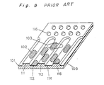
- FIG. 9 An enlarged section of this type of optical disk is shown in Fig. 9. Shown in Fig. 9 are a recording layer 101, recording pits 102, a beam spot 103 focused by an objective lens or other means, a transparent substrate 109 made of polycarbonate resin or other material, lands 111, 113, and 115, and grooves 112 and 114. As shown in the figure, the grooves and lands are of approximately equal width. A sequence of pre-formed pits 116 is formed in the beginning of each sector, and record the identification signal indicating location information on the optical disk.
- the grooves 112 and 114 and the pre-formed pits 116 are formed when manufacturing the transparent substrate 109 by, for example, an injection molding process that creates recesses of the grooves and pits and thus leaves the lands between the grooves and pits. As shown in Fig. 9, the recording pits 102 are formed on both the grooves and lands, and it is therefore possible to double the optical disk recording capacity compared with recording to only the grooves or lands.
- control information is also generally provided separately to the area (the "user data recording zone") to which user data is recorded (see ISO/IEC 13963, section 17.2.4).
- This control information area is commonly provided at, for example, the inside circumference of the disk, and is called the "control zone.”
- the control information includes media characteristics data such as the disk type and reflectance, the recommended optical beam power, recommended recording pulse width, and other drive control data for recording user data.
- This control information is used by the apparatus in which the optical disk is mounted to automatically compensate for differences in optical disk types and media characteristics resulting from differences between manufacturers.
- the control information thus helps improve the utility and ease of use of individual recording/reproducing apparatuses.
- the track pitch of the pit sequence representing the identification signal and the pit sequence written to the control zone are the same as the track pitch in the read-write zone, highly accurate injection molding technologies are required because the distance between pit sequences in the radial direction of the disk is half the groove pitch. As a result, manufacturing the transparent substrate of the disk is technically difficult.
- an optical information recording medium comprising a substrate having grooves and lands both formed thereon, at least one recording film formed on said substrate and having data tracks formed in a spiral or concentric pattern, and a read-write zone in which user data is recordable to both said grooves and lands.
- the present invention has been developed to overcome the above-described disadvantages.
- Another objective of the present invention is to provide an optical information recording medium for which the transparent substrate can be manufactured without difficulty to comprise by means of pit sequences a control zone containing pre-recorded control information or a read-only zone containing pre-recorded audio-video data or other information.
- the optical information recording medium according to the present invention comprises
- the pit sequences are formed at the same pitch as the grooves in the read-write zone in a radial direction of the substrate.
- the difference between the radial position of a selected data track in the read-only zone, and the radial position of a selected data track in the read-write zone is equal to an integer multiple of the groove pitch.
- the data tracks are divided into plural sectors comprising an identification signal area and a data area.
- the radial interval between the pit sequences is equal to the groove pitch, and the pit sequences are formed offset to an inside circumference or outside circumference side of the grooves from a track center line.
- the pit sequences in the read-only zone are arrayed continuously to the grooves of the read-write zone at a border between the read-write zone and the read-only zone.
- the radial interval between the grooves of the read-write zone and the pit sequences of the adjacent read-only zone is equal to the groove pitch.
- An optical disk according to the first embodiment of the present invention is described below using as the recording material of the disk a phase-change type, read-write material to which data can be recorded by changing the reflectance of the material.
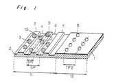
- Fig. 1 is an enlarged fragmentary perspective view of an optical disk according to the present embodiment.
- this optical disk comprises a transparent substrate 1 made of polycarbonate resin or other material, a recording layer 2 comprising one or more recording films covering the transparent substrate 1, lands 3, 5, and 7, and grooves 4 and 6.
- the grooves and lands are of approximately equal width as shown in the figure.
- the transparent substrate I has a plurality of pre-formed pits 8 and a plurality of recording pits 9 formed amorphously according to the user data.
- a beam spot 10 is used for recording and reproduction.
- the optical disk shown in Fig. 1 has a read-write zone 11 and a control zone 12 adjoining the read-write zone 11.
- the read-write zone 11 enables user data to be written to both the grooves and lands.
- the control zone 12 contains pre-recorded control information including media characteristics data and drive control data.
- the grooves 4 and 6 generally have a depth ranging from approximately ⁇ /10 to approximately ⁇ /4 in optical length (where ⁇ is the wavelength of the read laser light).
- a groove depth between approximately ⁇ /7 to ⁇ /5 is preferred because crosstalk from the adjacent track can thereby be reduced (see Japanese Laid-open Patent (unexamined) No. 5-282705).
- the pre-formed pits 8 have the same depth as the grooves.
- the track pitch TP1 of the data tracks in the read-write zone 11 is half the groove pitch GP.
- the track pitch TP2 of the data tracks in the control zone 12 is equal to the groove pitch GP.
- Fig. 2 depicts the sector format of an optical disk 13 embodying the present invention.
- the optical disk 13 has a plurality of data tracks 14 formed from sequences of grooves, lands, or pre-formed pits formed in a spiral pattern on the transparent substrate.
- the optical disk 13 also has a circular read-write zone 15 and a control zone 16 formed radially inwardly of and adjacent to the read-write zone 15.
- Each data track is divided into plural sectors 17.
- Each sector 17 comprises an identification signal block 18 and a data block 19.
- Each identification signal block 18 contains various fields, including a sector marker, synchronization pattern, address marker, and ID. These fields perform the following functions:
- the identification signal blocks are aligned in the radial direction of the disk.
- MCLV modified constant linear velocity
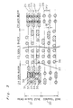
- Fig. 3 is an enlarged plan view of the major parts of an optical disk according to the present embodiment having a read-write zone 21 and a control zone 22.
- the read-write zone 21 is described first.
- the data tracks are formed as alternating grooves 31, 33, and 35 and lands 32 and 34.
- the identification signal is the optical disk identification signal declaring the track and/or sector address information on the optical disk, the sector markers, reference synchronization signal, or other disk control information.
- the pre-formed pits 36 representing the identification signal every other track between the groove track center lines 25 and land track center lines 26
- part of the beam spot 37 will pass over the pre-formed pits 36 in the identification signal block 23 whether the beam spot 37 is tracking grooves or lands.
- the reflected light is modulated by the pre-formed pits 36, and the address information can be detected whether tracking a groove or land.
- Data blocks 24 are where amorphous recording pits (marks) 38 are formed according to the video, audio, computer data, or other user data recorded.
- the control zone 22 is described next.
- the identification signal block 23 of the control zone 22 is identical to that of the read-write zone 21.
- Grooves are not formed to the data block 24 of the control zone 22, however, and control information is prerecorded as pre-formed pits on the center line 28 of the track.
- control information includes media characteristics data such as the disk type and reflectance, the recommended optical beam power, recommended recording pulse width, and other drive control data for recording user data.
- the track pitch TP2 of the pre-formed pits in the control zone 22 is equal to the groove pitch GP in the read-write zone 21.
- the distance between the center lines 27 and 28 of the data tracks adjacent to the border between the read-write zone 21 and the control zone 22 is also equal to the groove pitch GP.
- the pit sequence in the control zone 22 is thus aligned contiguously to an extension of the spiral trace formed by the center line of grooves in the read-write zone 21 because the data tracks are formed in a spiral pattern on the optical disk according to the present embodiment.
- a certain tolerance is thus achieved in the spacing between the pre-formed pit tracks, and molding the transparent substrate of the disk is made simpler, because the track pitch of the data tracks formed by the pre-formed pits in the data block 24 of the control zone 22 is the wide groove pitch GP and not the narrow track pitch of the data tracks in the read-write zone 21.
- the crosstalk from pre-formed pits on adjacent tracks is so small that control information read precision is also improved when the control information is reproduced by tracing the control zone 22 with the beam spot 37.
- the grooves in the read-write zone 21 and the pit sequence in the control zone 22 are arrayed at the same groove pitch GP in the radial direction.
- the feed pitch of the exposure laser can therefore be kept constant in the master disk cutting process when manufacturing the transparent substrates for the disks, and increasing the complexity of disk manufacture can be avoided.
- the information area of the optical disk 13 shown in Fig. 2 has been described as including the read-write zone 15 and control zone 16, other zones may be added as required.
- a recording test zone formed with a groove to the inside circumference of the control zone may be provided, and a second control zone may be provided to the outside of the read-write zone 15.
- the present invention has been described using a phase change material for the recording layer material, the present invention shall not be so limited and is applicable to any optical disk in which both grooves and lands are used as information tracks.
- the present invention can also be applied to magneto-optical disks using the magnetic super-resolution effect.
- the pit depth may differ from the groove depth. If the pit depth is set to ⁇ /4 in particular, beam spot diffraction is increased with the outstanding effect of increasing modulation of the identification signal.
- tests have demonstrated that the pre-formed pits 36 can be detected by the beam spot 37 when the pre-formed pits 36 are formed offset a further 1/16 groove pitch GP in the radial direction from the 1/4 groove pitch GP offset position in the radial direction (i.e., center of groove center line 25 and land center line 26).
- the pre-formed pits 36 representing the identification signal can be formed offset from 3/16 to 5/16 groove pitch GP from the center line of the data track.
- an optical disk 40 comprises in order from the inside circumference a lead-in zone 41, a data recording zone 42, and a lead-out zone 43.
- the data recording zone 42 further comprises a read-write zone 44 and a read-only zone 45.
- the control zone or other zone formed from the pre-formed pits as described in the first embodiment above is disposed in the lead-in zone 41 and lead-out zone 43.
- Digitized audio-video data, computer data, or other user data is stored to the data recording zone 42. While grooves and lands are formed in the read-write zone 44, only pre-formed pit sequences are formed in the read-only zone 45, and the data tracks formed in the read-write zone 44 and the read-only zone 45 are formed in a spiral pattern.
- the track pitch in the read-only zone 45 is equal to the groove pitch in the read-write zone 44. Because both grooves and lands are used as data tracks in the read-write zone 44, the track pitch in the read-only zone 45 is twice that of the read-write zone 44.
- the read-only zone 45 is formed to the inside circumference side of the read-write zone 44 in the radial direction in Fig. 4, it is also possible to form them to the outside circumference side in the radial direction.
- the data format of the present embodiment is described next.
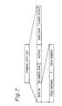
- the sector format of the optical disk in this embodiment is shown in Figs. 5A-5E.
- the sectors in the read-write zone 44 are described below.
- each track is divided into n sectors as shown in Fig. 5A.
- each sector comprises:
- the identification signal field is also known as the "header” and is formed from pre-formed pit sequences.
- the mirror field contains no pre-formed pits or grooves, and is used to detect the amount of light reflected when the beam spot is emitted to the mirror field to control reflectance.
- the gap field, first preamble field, main data signal field, guard data field, and buffer field compose recording fields, and contain either grooves or lands.
- the gap field is provided to gain time for signal processing between when the beam spot passes the identification signal and until it passes the first preamble field.
- a single frequency sequence of recording pits is formed in the first preamble field to generate a synchronization clock for reproducing the data from the main data signal field.
- a dummy data sequence of recording pits is recorded to the guard data field following the recording pits written to the main data signal field.
- the guard data field is required because of the damage to the recording pits occurring after repeated writing. More specifically, repeated writing damages (degrades) the ends of the recording pits, and as writing to the same recording pits continues, this damage tends to extend upstream in the direction of beam spot travel. By providing the guard data field downstream of the main data signal field, however, this damage to the recording pits can be absorbed in the guard data field and prevented from extending to the main data signal field.
- the buffer field is provided to assure that all recording pit sequences can be written to the area between the identification signal fields even if variation in the rotational velocity of the disk occurs during recording, causing the total length per sector of the recording pit sequences to increase.
- the identification signal field is divided into four sub-fields as shown in Fig. 5C, i.e., PID1, PID2, PID3, and PID4. Each of these sub-fields is divided as shown in Fig. 5D into a second preamble area, an address marker area, an identification information area, an error correction code area, and a postamble area.
- the second preamble area and the postamble area contain a single frequency sequence of recording pits to generate a synchronization clock for reproducing the data from the identification signal area.
- the address marker area contains a recording pit sequence formed in a particular pattern to indicate that the next identification information area begins.
- the identification information area includes a sector data block and an absolute address block.
- An error correction code is also added to prevent data read errors from the identification information area.
- the sector data includes flags identifying, for example, the PID type (i.e., which of PID1 - PID4 the sub-field is), zone type (lead-in, lead-out, or data recording zone), and sector type (read-only or read-write).
- the absolute address number includes the sector number and track number, and is therefore the same for PID1 - PID4.
- Fig. 6 shows the pattern of the identification signal field of an optical disk according to the present invention.
- the horizontal direction indicates the track direction
- the vertical direction indicates the radial direction of the disk.
- the track direction is shown shorter in scale compared with the radial direction of the disk.
- the beam spot traces from left to right as seen in the figure. Also shown are the identification signal field 50, mirror field 51, gap field 52, and buffer field 53. Also shown in the gap field 52 and buffer field 53 are the data track grooves 54 and data track lands 55.
- the four sub-fields PID1 56 - PID4 59 are also shown in the identification signal field 50.
- Each sub-field contains pre-formed pit sequences.
- PID1 and PID3 are offset from the center of groove to the left in the direction of beam spot travel, and PID2 and PID4 are offset to the right.
- the center of the sub-fields is positioned near the border with the adjacent land. More specifically, the offset from the groove center of the pre-formed pit sequences forming PID1 - PID4 is about 1/4 groove pitch as described above.
- the data from the identification signal field can be detected when reading both grooves and lands.
- the data from the identification signal field can be detected with high precision even if the beam spot gets off track.
- an error detection code is calculated for 2048 bytes'of main data, data ID, data ID error correction code, and reservation information.
- the 2048 bytes of main data, data ID, data ID error correction code, reservation information and error detection code are defined as the primary data unit.
- the data contained in the primary data unit is scrambled.
- Reed-Solomon error correction coding is then applied to sixteen scrambled primary data units, which are treated as one data block, thus generating sixteen secondary data units.
- the data in each of the sixteen secondary data units is then processed with 8-16 modulation converting 8-bit/symbol data to 16 channel bits according to specific rules.
- the synchronization pattern is then inserted, producing sixteen tertiary data units. These tertiary data units are then recorded to 16 sectors of main data signal field.
- the data ID includes the data field information and the data field number.
- the data field information contains flags identifying, for example, the track type (groove or land), zone type (lead-in, lead-out, or data recording zone), and data type (read-only or read-write).
- the data field number is the same as the absolute address.
- the read-only zone 45 differs in that pre-formed pit sequences are formed at the location of the grooves in the read-write zone 44, and the pre-formed pit sequences are not formed at the location of the lands.
- the track pitch of the recording area in the read-only zone is twice the track pitch of the recording field in the read-write zone.
- the track pitch of the recording field in the read-only zone is the same as the track pitch in the control zone.
- the arrangement of the pre-formed pit sequences in the identification signal field, the rules for the sector information and the data field information, the coding and modulation of the main data in the main data signal field, and other parameters are the same as in the read-write zone.
- the flag identifying the data type For example, of the data field information flags in this read-only zone, it is only necessary for the flag identifying the data type to indicate read-only information, and the flag identifying the track type to indicate a groove track.
- the linear recording density of the main data and the recording channel bit length in this zone are also equal to those in the read-write zone. This makes it possible to use the same reproduction signal processing circuit for both the read-write zone 44 and the read-only zone 45.
- a pre-formed pit sequence is preferably formed in the read-only zone. This enables continuous tracking control in both zones, and thus stabilizes data reproduction.
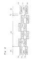
- Fig. 8 is an enlarged plan view of the identification signal field in the read-only zone of the optical disk according to the present embodiment. Note the pre-formed pits 60, beam spot 61, and track center line 62. The beam spot 61 traces the track center line 62 in the direction of the arrow.
- PID1 63, PID2 64, PID3 65, and PID4 66 are recorded by pre-formed pits 60, and constitute the identification signal field 67.
- the pre-formed pits 60 are offset to the left in the direction of beam spot travel, and the pre-formed pits 60 in PID2 and PID4 are offset an equal amount to the right.
- This offset distance is about 1/4 groove pitch GP.
- pre-formed pits 60 in the identification signal field 67 is the same as that shown in Fig. 6.
- Pre-formed pits and grooves are not formed in the mirror field 68, while pre-formed pits are formed in the gap field 69 and the buffer field 70.
- the control zone in the lead-in zone 41 and the lead-out zone 43 has the same sector format as that of the read-only zone 45. All data in the control zone is recorded as pre-formed pits.
- the main data may include, for example, the disk type, recording density, reflectance, and other media characteristics, the data transfer rate, average linear recording velocity, the recommended optical beam power, recommended recording pulse width, and other drive control data.
- the track pitch in the lead-in zone 41, lead-out zone 43, and read-only zone 45 is twice the track pitch of the read-write zone 44.
- the arrangement of the pre-formed pits in the identification signal area is the same in each of these zones, and the track pitch is also equal.
- a recording/reproducing system for the optical disk according to the present embodiment uses a groove pitch GP of 1.48 ⁇ m, a recording pit length of 0.41 ⁇ m/bit, a laser beam wavelength of 650 nm, and an objective lens aperture of 0.6.
- the track pitch is 0.74 ⁇ m. In the read-only zone, however, the pre-formed pit sequences are formed on an extension of the grooves, and the track pitch is therefore 1.48 ⁇ m.
- the track pitch in the lead-in zone 41, lead-out zone 43, and read-only zone 45 is twice the track pitch of the read-write zone 44. This provides a certain tolerance in the spacing between the pre-formed pit tracks in the radial direction, and thus makes molding the transparent substrate of the disk simpler. Signal reading precision is also improved because crosstalk from pre-formed pits on adjacent tracks is satisfactorily at a low level. By also structuring the identification signal field the same in each zone, signals from the identification signal field can be read using the same detection circuit in all disk zones.
- Application software and other read-only data can be recorded to the read-only zone to improve the ease of use because the read-only zone is formed to either the inside circumference side or outside circumference side of the read-write zone wherein user-data is recorded to both grooves and lands.
- a certain tolerance is achieved in the spacing in the radial direction between the pre-formed pit tracks, and molding the transparent substrate of the disk is made simpler, because the track pitch of the data tracks formed by the pre-formed pits in the read-only zone is the wide groove pitch and not the narrow track pitch of the data tracks in the read-write zone. Because the read-only zone can thus be easily added to an optical information recording medium comprising a read-write zone in which both grooves and lands are used as data tracks, the information signal recording capacity is great. Using the control information pre-recorded to the read-only zone, the ease of use of the device in which the optical information recording medium of the present invention is mounted can also be improved.
- the identification signal can be reproduced when reading both groove and land data tracks even without forming the identification signal pit sequence on both grooves and lands because the pitch in the radial direction between the pit sequences in the identification signal field is equal to the groove pitch, and the pit sequences are offset in the radial direction from the track center to either the inside or outside circumference.
- the grooves of the read-write zone and the pit sequences of the read-only zone are continuous.
- the distance in the radial direction between the grooves of the read-write zone and the pit sequences of the adjacent read-only zone is equal to the groove pitch.
Landscapes
- Engineering & Computer Science (AREA)
- Software Systems (AREA)
- Theoretical Computer Science (AREA)
- Optical Recording Or Reproduction (AREA)
Claims (3)
- Milieu d'enregistrement optique d'informations (13, 40) comprenant :caractérisé en ce que :un substrat en forme de disque (1) possédant des rainures (4, 6, 31, 33, 35, 54), des saillies (3, 5, 7, 32, 34, 55) et des séquences de creux formées sur celui-ci ;au moins un film d'enregistrement (2) couvrant au moins une surface du substrat en forme de disque (1) et possédant une pluralité de pistes de données formées selon une configuration en spirale ou concentrique ;une zone de lecture/écriture (11, 15, 21, 44) définie par une première partie du substrat en forme de disque (1), dans laquelle les données de l'utilisateur peuvent être enregistrées sur les pistes de données formées par les rainures et les méplats et qui comprend les premières séquences de creux (9) ; etune zone de lecture seule (12, 16, 22) définie par une deuxième partie du substrat en forme de disque (1), qui est adjacente radialement à la première partie, dans laquelle les pistes de données sont formées par les deuxièmes séquences de creux (8) ;dans lequel les pistes de données sont divisées en plusieurs secteurs (17) et dans lequel chaque secteur (17) comprend un champ de signaux d'identification (18, 23, 50, 67) et un champ de données (19, 24) ;tant dans la zone de lecture/écriture (11, 15, 21, 44) que dans la zone de lecture seule (12, 16, 22, 45), une distance radiale d'intervalle entre les premières séquences de creux dans le champ de signaux d'identification (18, 23, 50, 67) et une distance radiale d'intervalle entre les deuxièmes séquences de creux dans le champ de signaux d'identification (18, 23, 50, 67) sont toutes les deux égales à une distance radiale d'intervalle entre les rainures (4, 6, 31, 33, 35, 54) ;les premières et deuxièmes séquences dans le champ du signaux d'identification (18, 23, 50, 67) sont formées radialement de façon désaxée à partir d'un axe de piste des pistes de données ; etles premières et deuxièmes séquences de creux sont détectables par un même circuit de détection.
- Milieu d'enregistrement optique d'informations (13, 40) selon la revendication 1, dans lequel les pistes de données sont formées sur le substrat en forme de disque (1) selon la configuration en spirale, et dans lequel les deuxièmes séquences de creux dans la zone de lecture seule (45) sont alignées de manière contiguë avec les rainures de la zone de lecture/écriture (11, 15, 21, 44) au niveau d'une limite entre la zone de lecture/écriture (11, 15, 21, 44) et la zone de lecture seule (45).
- Milieu d'enregistrement optique d'informations (13, 40) selon la revendication 1, dans lequel les pistes de données sont formées sur le substrat en forme de disque (1) selon la configuration concentrique, et dans lequel une distance radiale d'intervalle entre les rainures de la zone de lecture/écriture (11, 15, 21, 44) et les deuxièmes séquences de creux de la zone de lecture seule (45) est égale à la distance radiale d'intervalle entre les rainures de la zone de lecture/écriture (11, 15, 21, 44).
Applications Claiming Priority (6)
| Application Number | Priority Date | Filing Date | Title |
|---|---|---|---|
| JP26124395 | 1995-10-09 | ||
| JP26124395 | 1995-10-09 | ||
| JP261243/95 | 1995-10-09 | ||
| JP20851/96 | 1996-02-07 | ||
| JP2085196 | 1996-02-07 | ||
| JP2085196 | 1996-02-07 |
Publications (2)
| Publication Number | Publication Date |
|---|---|
| EP0768648A1 EP0768648A1 (fr) | 1997-04-16 |
| EP0768648B1 true EP0768648B1 (fr) | 2001-08-08 |
Family
ID=26357851
Family Applications (1)
| Application Number | Title | Priority Date | Filing Date |
|---|---|---|---|
| EP96116142A Expired - Lifetime EP0768648B1 (fr) | 1995-10-09 | 1996-10-09 | Milieu d'enregistrement optique d'information |
Country Status (3)
| Country | Link |
|---|---|
| US (1) | US5835479A (fr) |
| EP (1) | EP0768648B1 (fr) |
| DE (1) | DE69614338T2 (fr) |
Families Citing this family (20)
| Publication number | Priority date | Publication date | Assignee | Title |
|---|---|---|---|---|
| JP3707833B2 (ja) * | 1995-08-10 | 2005-10-19 | 株式会社東芝 | 光ディスク装置 |
| US6538963B1 (en) * | 1996-06-04 | 2003-03-25 | Lg Electronics Inc. | Optical disk and recording/reproducing device thereof |
| US6600713B1 (en) * | 1996-06-26 | 2003-07-29 | Sun Microsystems, Inc. | Recording media having separate read only and read/write areas |
| TW357345B (en) * | 1996-06-26 | 1999-05-01 | Matsushita Electric Industrial Co Ltd | CD having re-write area and ROM area |
| EP1006514B1 (fr) | 1996-10-23 | 2003-01-02 | Matsushita Electric Industrial Co., Ltd. | Disque optique |
| DE69703751T2 (de) * | 1996-10-25 | 2001-04-19 | Matsushita Electric Industrial Co., Ltd. | Optische Platte mit oszillierenden Stegen und Rillen |
| JP3201289B2 (ja) * | 1996-11-12 | 2001-08-20 | 日本ビクター株式会社 | 光ディスク |
| KR19980084908A (ko) * | 1997-05-27 | 1998-12-05 | 윤종용 | 비휘발성 메모리를 갖는 광 디스크와 비휘발성 메모리를 갖는 광 디스크를 사용하기 위한 광 디스크 장치 및 그 제어 방법 |
| JP3997564B2 (ja) * | 1997-06-10 | 2007-10-24 | ソニー株式会社 | 光学的記録媒体の製造方法 |
| JP4144054B2 (ja) * | 1997-07-24 | 2008-09-03 | ソニー株式会社 | 光ディスクの記録方法 |
| US5986997A (en) * | 1997-09-10 | 1999-11-16 | Imation Corp. | Updatable optical data storage disc having reduced crosstalk between tracks, and drive for same |
| JPH11283291A (ja) * | 1998-01-30 | 1999-10-15 | Fujitsu Ltd | 記憶装置、光学的記録媒体及び情報記録方法 |
| JP4036400B2 (ja) * | 1998-03-20 | 2008-01-23 | 株式会社東芝 | 光ディスク装置 |
| JP4272279B2 (ja) | 1998-09-28 | 2009-06-03 | パナソニック株式会社 | 光学的情報記録装置、光学的情報記録媒体および光学的情報記録方法 |
| JP2002536781A (ja) * | 1999-02-10 | 2002-10-29 | コーニンクレッカ フィリップス エレクトロニクス エヌ ヴィ | 記録担体上にidを記憶する方法、装置及び記録担体 |
| JP2001126408A (ja) * | 1999-10-29 | 2001-05-11 | Sony Corp | 光学式回転記録媒体、アドレス情報記録方法、アドレス情報復元方法、光学式記録装置、光学式再生装置、および、光学式記録・再生装置 |
| EP1117095B1 (fr) * | 2000-01-14 | 2006-03-22 | Pioneer Corporation | Disque optique enregistrable et méthode d'enregistrement |
| JP3962522B2 (ja) * | 2000-02-14 | 2007-08-22 | パイオニア株式会社 | 情報記録媒体 |
| WO2001065552A1 (fr) * | 2000-02-28 | 2001-09-07 | Fujitsu Limited | Disque optique |
| WO2001073771A2 (fr) * | 2000-03-29 | 2001-10-04 | Matsushita Electric Industrial Co., Ltd. | Disque optique et dispositif d'enregistrement et de lecture pour ledit disque optique |
Family Cites Families (12)
| Publication number | Priority date | Publication date | Assignee | Title |
|---|---|---|---|---|
| US5247494A (en) * | 1984-06-08 | 1993-09-21 | Matsushita Electric Industrial Co. Ltd. | Method for recording and reproducing information on and from an optical disk having a read-only recorded zone and a writable and readable zone using a spot laser light |
| US5214627A (en) * | 1989-02-08 | 1993-05-25 | Fujitsu Limited | Optical disk having read-exclusive and write-enable regions |
| US5138598A (en) * | 1990-01-25 | 1992-08-11 | Sony Corporation | Optical disk having relatively wide ram tracks and relatively narrow rom tracks |
| JP3089497B2 (ja) * | 1991-08-20 | 2000-09-18 | ソニー株式会社 | 記録再生装置及び再生装置 |
| JP2868682B2 (ja) * | 1992-05-15 | 1999-03-10 | シャープ株式会社 | 光ディスク |
| US5452284A (en) * | 1992-09-14 | 1995-09-19 | Matsushita Electric Industrial Co., Ltd. | Optical recording/reproducing medium and apparatus using land and groove encoded information signals and identification signals including position information |
| JP3133509B2 (ja) * | 1992-09-29 | 2001-02-13 | パイオニア株式会社 | 光ディスク及び光ディスク駆動装置 |
| US5517485A (en) * | 1993-02-26 | 1996-05-14 | Matsushita Electric Industrial Co., Ltd. | Optical information recording medium having first and second tracks and apparatus for recording to and reproducing from the medium |
| JP3237982B2 (ja) * | 1993-03-16 | 2001-12-10 | 株式会社東芝 | 光学的情報記録再生装置及び光学的情報記録媒体 |
| JP3150014B2 (ja) * | 1993-07-16 | 2001-03-26 | 株式会社リコー | 光学的情報記録媒体 |
| US5602823A (en) * | 1993-07-30 | 1997-02-11 | Ricoh Company, Ltd. | Optical recording medium having pre-formatted patterns arrange by shifting phases |
| JPH0822640A (ja) * | 1994-07-05 | 1996-01-23 | Matsushita Electric Ind Co Ltd | 光ディスクおよび光ディスク記録方法 |
-
1996
- 1996-10-08 US US08/727,307 patent/US5835479A/en not_active Expired - Fee Related
- 1996-10-09 DE DE69614338T patent/DE69614338T2/de not_active Expired - Fee Related
- 1996-10-09 EP EP96116142A patent/EP0768648B1/fr not_active Expired - Lifetime
Also Published As
| Publication number | Publication date |
|---|---|
| DE69614338D1 (de) | 2001-09-13 |
| DE69614338T2 (de) | 2002-05-08 |
| EP0768648A1 (fr) | 1997-04-16 |
| US5835479A (en) | 1998-11-10 |
Similar Documents
| Publication | Publication Date | Title |
|---|---|---|
| EP0768648B1 (fr) | Milieu d'enregistrement optique d'information | |
| US6064644A (en) | Optical recording medium having particular arrangement of prepits and manufacturing method thereof | |
| EP1271490B1 (fr) | Disque optique | |
| EP0801382B1 (fr) | Appareil et méthode d'enregistrement et/ou de reproduction optique d'information | |
| EP0896325B1 (fr) | Disque optique à haute densité, appareil de reproduction de disque optique, et méthode de fabrication d'une matrice de disque optique | |
| US20010004340A1 (en) | Optical record carrier and scanning device | |
| US6404729B1 (en) | Optical disc | |
| JPH06295443A (ja) | 光記録媒体およびその記録再生装置 | |
| US5654953A (en) | Optical disk and method of manufacturing the same | |
| JPH09274733A (ja) | 光情報記録媒体 | |
| JPH04289539A (ja) | 光ディスク | |
| JPH08273168A (ja) | 光ディスクの記録及び再生方法 |
Legal Events
| Date | Code | Title | Description |
|---|---|---|---|
| PUAI | Public reference made under article 153(3) epc to a published international application that has entered the european phase |
Free format text: ORIGINAL CODE: 0009012 |
|
| 17P | Request for examination filed |
Effective date: 19961010 |
|
| AK | Designated contracting states |
Kind code of ref document: A1 Designated state(s): DE FR GB |
|
| 17Q | First examination report despatched |
Effective date: 19991222 |
|
| GRAG | Despatch of communication of intention to grant |
Free format text: ORIGINAL CODE: EPIDOS AGRA |
|
| GRAG | Despatch of communication of intention to grant |
Free format text: ORIGINAL CODE: EPIDOS AGRA |
|
| GRAH | Despatch of communication of intention to grant a patent |
Free format text: ORIGINAL CODE: EPIDOS IGRA |
|
| GRAH | Despatch of communication of intention to grant a patent |
Free format text: ORIGINAL CODE: EPIDOS IGRA |
|
| GRAA | (expected) grant |
Free format text: ORIGINAL CODE: 0009210 |
|
| AK | Designated contracting states |
Kind code of ref document: B1 Designated state(s): DE FR GB |
|
| REF | Corresponds to: |
Ref document number: 69614338 Country of ref document: DE Date of ref document: 20010913 |
|
| ET | Fr: translation filed | ||
| REG | Reference to a national code |
Ref country code: GB Ref legal event code: IF02 |
|
| PLBE | No opposition filed within time limit |
Free format text: ORIGINAL CODE: 0009261 |
|
| STAA | Information on the status of an ep patent application or granted ep patent |
Free format text: STATUS: NO OPPOSITION FILED WITHIN TIME LIMIT |
|
| 26N | No opposition filed | ||
| PGFP | Annual fee paid to national office [announced via postgrant information from national office to epo] |
Ref country code: DE Payment date: 20081014 Year of fee payment: 13 |
|
| PGFP | Annual fee paid to national office [announced via postgrant information from national office to epo] |
Ref country code: FR Payment date: 20081014 Year of fee payment: 13 |
|
| PGFP | Annual fee paid to national office [announced via postgrant information from national office to epo] |
Ref country code: GB Payment date: 20081008 Year of fee payment: 13 |
|
| REG | Reference to a national code |
Ref country code: FR Ref legal event code: ST Effective date: 20100630 |
|
| PG25 | Lapsed in a contracting state [announced via postgrant information from national office to epo] |
Ref country code: FR Free format text: LAPSE BECAUSE OF NON-PAYMENT OF DUE FEES Effective date: 20091102 Ref country code: DE Free format text: LAPSE BECAUSE OF NON-PAYMENT OF DUE FEES Effective date: 20100501 |
|
| PG25 | Lapsed in a contracting state [announced via postgrant information from national office to epo] |
Ref country code: GB Free format text: LAPSE BECAUSE OF NON-PAYMENT OF DUE FEES Effective date: 20091009 |