EP0768697A1 - Spritzwassergeschützter modularer Sicherungshalter mit verriegelbarem Deckel - Google Patents
Spritzwassergeschützter modularer Sicherungshalter mit verriegelbarem Deckel Download PDFInfo
- Publication number
- EP0768697A1 EP0768697A1 EP96201679A EP96201679A EP0768697A1 EP 0768697 A1 EP0768697 A1 EP 0768697A1 EP 96201679 A EP96201679 A EP 96201679A EP 96201679 A EP96201679 A EP 96201679A EP 0768697 A1 EP0768697 A1 EP 0768697A1
- Authority
- EP
- European Patent Office
- Prior art keywords
- cover
- fuse
- teeth
- arms
- holder
- Prior art date
- Legal status (The legal status is an assumption and is not a legal conclusion. Google has not performed a legal analysis and makes no representation as to the accuracy of the status listed.)
- Withdrawn
Links
- 230000001681 protective effect Effects 0.000 claims abstract description 3
- 230000008878 coupling Effects 0.000 claims description 21
- 238000010168 coupling process Methods 0.000 claims description 21
- 238000005859 coupling reaction Methods 0.000 claims description 21
- 239000000463 material Substances 0.000 claims description 7
- 239000004033 plastic Substances 0.000 claims description 7
- 229920003023 plastic Polymers 0.000 claims description 7
- 230000009471 action Effects 0.000 claims description 4
- 230000006835 compression Effects 0.000 claims description 3
- 238000007906 compression Methods 0.000 claims description 3
- 238000003780 insertion Methods 0.000 claims description 3
- 230000037431 insertion Effects 0.000 claims description 3
- 239000007921 spray Substances 0.000 claims description 3
- 230000002093 peripheral effect Effects 0.000 description 7
- 238000005452 bending Methods 0.000 description 5
- 210000002105 tongue Anatomy 0.000 description 4
- 239000000428 dust Substances 0.000 description 2
- 230000000694 effects Effects 0.000 description 2
- 238000009825 accumulation Methods 0.000 description 1
- 230000002411 adverse Effects 0.000 description 1
- 238000006243 chemical reaction Methods 0.000 description 1
- 239000003086 colorant Substances 0.000 description 1
- 210000005224 forefinger Anatomy 0.000 description 1
- 230000006872 improvement Effects 0.000 description 1
- 238000007689 inspection Methods 0.000 description 1
- 238000009434 installation Methods 0.000 description 1
- 238000012423 maintenance Methods 0.000 description 1
- 230000008439 repair process Effects 0.000 description 1
- 210000003813 thumb Anatomy 0.000 description 1
Images

Classifications
-
- H—ELECTRICITY
- H01—ELECTRIC ELEMENTS
- H01H—ELECTRIC SWITCHES; RELAYS; SELECTORS; EMERGENCY PROTECTIVE DEVICES
- H01H85/00—Protective devices in which the current flows through a part of fusible material and this current is interrupted by displacement of the fusible material when this current becomes excessive
- H01H85/02—Details
- H01H85/20—Bases for supporting the fuse; Separate parts thereof
- H01H85/2045—Mounting means or insulating parts of the base, e.g. covers, casings
-
- H—ELECTRICITY
- H01—ELECTRIC ELEMENTS
- H01H—ELECTRIC SWITCHES; RELAYS; SELECTORS; EMERGENCY PROTECTIVE DEVICES
- H01H85/00—Protective devices in which the current flows through a part of fusible material and this current is interrupted by displacement of the fusible material when this current becomes excessive
- H01H85/02—Details
- H01H85/34—Distinguishing marks, e.g. colour coding
-
- H—ELECTRICITY
- H01—ELECTRIC ELEMENTS
- H01R—ELECTRICALLY-CONDUCTIVE CONNECTIONS; STRUCTURAL ASSOCIATIONS OF A PLURALITY OF MUTUALLY-INSULATED ELECTRICAL CONNECTING ELEMENTS; COUPLING DEVICES; CURRENT COLLECTORS
- H01R13/00—Details of coupling devices of the kinds covered by groups H01R12/70 or H01R24/00 - H01R33/00
- H01R13/62—Means for facilitating engagement or disengagement of coupling parts or for holding them in engagement
- H01R13/627—Snap or like fastening
- H01R13/6271—Latching means integral with the housing
- H01R13/6273—Latching means integral with the housing comprising two latching arms
Definitions
- the present invention relates to a splash-proof, modular fuse-holder with a cover-release protection device, particularly for use in the automotive field.
- Splash-proof modular fuse holders for housing single fuses of the type with contact blades, which are used particularly in the automotive field, are known.
- a fuse housing in the fuse-holder body is closed by a removable cover with the interposition of a resilient seal.
- the removable cover is engaged on the body by means of snap teeth which have to ensure firm engagement between the body and the cover without relative yielding (to ensure adequate compression of the seal) and, at the same time, must allow the cover to be removed easily from the body, possibly without the aid of a tool, in order to replace a burnt-out fuse or even simply to inspect the fuse.
- the engagement teeth have retaining sides which have a positive rake and are not perpendicular to the direction of engagement and release so that the manual exertion of a suitable pulling force on the cover causes the teeth which, advantageously, are mounted on the ends of resilient tongues, to yield and be released.
- connection can yield in the direction in which the seal is compressed, which adversely affects the imperviousness of the coupling between the body and the cover.
- the present invention remedies these limitations and provides a splash-proof, modular fuse-holder with a body closed by a cover which is coupled to the body in a coupling plane and is engaged firmly on the body by means of pairs of engagement teeth, the teeth having retaining sides with a zero or negative rake relative to the coupling plane and being formed, respectively, on opposed sides of the body and on first ends of two first-order levers which are fixed to the cover and are preferably integral therewith and which act as resilient clamps which can be opened by manual action exerted on the second ends of the levers to bring them close together.
- protective shields are disposed beside the power arms of the levers and prevent accidental operation of the clamps or operation of the adjacent clamps when several fuse-holder modules are fitted side by side.
- a further requirement for modular fuse-holders is to distinguish the fuse-holder by using a colour which identifies the rating of the fuse which the fuse-holder is intended to house.
- the present invention advantageously provides a modular fuse-holder in which a coloured block is housed irreversibly inside the fuse-holder body and is visible only when the cover has been opened and the fuse has been removed from the fuse-holder body.
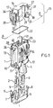
- a modular fuse-holder according to the present invention comprises a generally rectangular, parallelepipedal body 1 of insulating plastics material inside which suitable housings are formed for clamps 2, 3 for electrical contact with the electrical terminals of a fuse, particularly blade terminals of a blade fuse, not shown, and for a secondary clamping element or "secondary lock" 4 of known type which ensures that the contact clamps are irremovable once they are fitted in the body.
- the housings for the clamps 2, 3 and for the "secondary lock" are accessible from a lower wall of the body 1 closed by a lower cover 5 of plastics material which is engaged on the body 1 by the coupling of resilient engagement eyes 6, 7, 8, 9 with corresponding engagement teeth 10, 11, 12, formed on the peripheral wall of the body.
- Engagement teeth and slots are formed on two opposed faces of the peripheral wall of the body 1 for the juxtaposition and mutual engagement of several fuse-holder modules, in known manner.
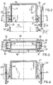
- the body 1 is closed at the top by a removable cover 15 which is also of generally rectangular, parallelepipedal shape, is hollow, and is open at the bottom and which has a top wall 16 and two pairs of opposed peripheral walls 17, 18, 19, 20, clearly visible in Figures 2 and 3.
- a removable cover 15 which is also of generally rectangular, parallelepipedal shape, is hollow, and is open at the bottom and which has a top wall 16 and two pairs of opposed peripheral walls 17, 18, 19, 20, clearly visible in Figures 2 and 3.
- the lower free edges of the peripheral walls have an annular recess 21 in which a resilient seal 22, preferably an "O-ring" is engaged.
- the lower edges of the peripheral walls of the cover are coupled with a lip 23 which is formed on the upper wall of the body 1 and engages in the annular recess 21 to compress the seal 22 and ensure that the coupling is impervious to spray.
- the body and the cover 15 thus coupled in the plane of the seal, which is defined below as the coupling plane, form a splash-proof housing for a fuse, not shown.
- the body 1 has two engagement teeth 24 and 25 on two opposed faces of the peripheral wall (naturally not those intended to be disposed beside other fuse-holder modules), close to the lip 23.
- the cover 15 in turn has two fairly stiff arms 26 and 27 extending in a direction perpendicular to the coupling plane on two opposed peripheral walls 17,19.
- the two arms are preferably moulded integrally with the cover 15 from plastics material and each is connected to the walls of the cover in an intermediate position of the arm by a pair of projecting brackets or supports 28, 29, 30, 31, also of plastics material.
- Each of the two arms 26, 27 with the respective projecting supports in practice forms a first-order lever the fulcrum of which is provided by the projecting support which has dimensions such as to ensure suitable resilience upon bending.
- the lever has a stable rest position defined by the projecting support when it is not subject to bending stress but action exerted on one or other end of the lever in a direction perpendicular to the direction in which its arms extend causes bending of the projecting support and pivoting of the lever.
- the lower ends of the arms 26, 27 extend from the cover beyond the plane of the coupling between the cover and body 1 and have respective engagement teeth 32, 33 which engage respective engagement teeth 24, 25 of the body.
- each of the teeth 24, 25, 32, 33 has a retaining side which preferably has a negative rake relative to the coupling plane with a rake angle ⁇ of between 0 and 10 0 .
- the opposite sides of the two teeth are advantageously inclined with a positive rake to form a stress-raising surface which allows the two teeth to be superimposed gradually by the movement of the cover 15 towards the body 1.
- the operation is extremely easy and requires no tools.
- the cover 15 is released from the body 1, however, by the exertion on the two opposite ends of the arms 25 and 26 to those provided with the engagement teeth 30, 31, of a force which tends to bring these two ends close together.
- This level of force can easily be exerted manually without tools and with one hand if the two ends are gripped between a thumb and forefinger.
- a bending moment is thus transmitted to the brackets supporting the arms and causes the arms to pivot and release the teeth.
- the two arms 26, 27 behave like a resilient clamp.
- the cover 15 advantageously has shields 34, 35, 36, 37 disposed in pairs beside the two arms 25, 26 for preventing manual pressure simultaneously being exerted on two arms of adjacent modules.
- the body 1 in addition to holes 38, 39 for the insertion of contact blades of the fuse, the body 1 also has a prismatic housing 40 interposed between the holes 38, 39 on its upper wall, inside the lip 23, for a plate 41 of coloured plastics material which has resilient tongues with snap teeth and which engages irreversibly in the housing 40.
- the plate When the fuse-holder is open and the fuse has been removed, the plate identifies the rating of the fuse to be housed in the fuse-holder and, clearly, since it is housed in the fuse housing, it is protected from dust and dirt and is visible only when the fuse-holder is open.
- the engagement and release clamps may be formed integrally with the cover, the engagement and release clamps may be formed as separate elements with resilient tongues acting as leaf springs for biasing the clamps towards the engagement position.
- the arms or clamps 42, 43 which are wholly equivalent to the arms 26, 27 of Figure 2, have pins 44, 45 disposed in intermediate positions of the arms and engaging in corresponding holes in the lateral shields 46, 47 (or equivalent supports) forming a hinge connection.
- resilient tongues 46, 47 formed integrally with the arms 42, 43 bear against the walls of the cover and act as leaf springs for biasing the arms towards the engagement position.
- a further improvement which may be applied consists of the provision of an interlocking system which ensures that the engagement teeth of the cover and of the body are aligned in the direction of insertion and, at the same time, prevents the engaged cover from being displaced relative to the body in the coupling plane.
- the interlocking alignment system also prevents relative rotation between the engaged body and cover which could be brought about by incorrect handling.
- each of the engagement teeth on the fuse-holder body 1 is formed by a pair of adjacent teeth separated by a mortice.
- the engagement tooth 24 formed by the two teeth 24A, 24B, separated by a mortice 48 and disposed on a side wall of the body 1, are clearly visible in Figure 5.
- a corresponding pair of engagement teeth is formed on the opposite wall of the body 1.
- the engagement teeth 32, 33 formed on the ends of the arms 26, 27 of the cover in turn have, on the retaining side, a tenon which engages in the corresponding mortice and ensures precise coupling of the teeth.
- a tenon which engages in the corresponding mortice and ensures precise coupling of the teeth.
- the same effect may be achieved by a reciprocal arrangement, that is, by the provision of double teeth 32, 33 with an intermediate mortice and the provision of a tenon projecting on the retaining side of the teeth such as the tooth 24 of the body.
- a reciprocal arrangement may also be used in this embodiment, that is, tabs may be provided extending at the lateral ends of the teeth such as the tooth 24 of the body 1, the tabs being disposed beside the teeth of the cover when the cover is engaged but not preventing translation relative to the teeth of the body.
Landscapes
- Fuses (AREA)
- Connection Or Junction Boxes (AREA)
Applications Claiming Priority (2)
| Application Number | Priority Date | Filing Date | Title |
|---|---|---|---|
| ITMI950689 IT237206Y1 (it) | 1995-10-09 | 1995-10-09 | Portafusibile modulare a prova di spruzzo con dispositivo protettodi sgancio coperchio |
| ITMI950689U | 1995-10-09 |
Publications (1)
| Publication Number | Publication Date |
|---|---|
| EP0768697A1 true EP0768697A1 (de) | 1997-04-16 |
Family
ID=11371212
Family Applications (1)
| Application Number | Title | Priority Date | Filing Date |
|---|---|---|---|
| EP96201679A Withdrawn EP0768697A1 (de) | 1995-10-09 | 1996-06-15 | Spritzwassergeschützter modularer Sicherungshalter mit verriegelbarem Deckel |
Country Status (2)
| Country | Link |
|---|---|
| EP (1) | EP0768697A1 (de) |
| IT (1) | IT237206Y1 (de) |
Cited By (2)
| Publication number | Priority date | Publication date | Assignee | Title |
|---|---|---|---|---|
| WO2012036643A1 (en) * | 2010-09-17 | 2012-03-22 | Viroj Khanampornpan | Fluorescent lamp holder assembly |
| CN117027507A (zh) * | 2023-08-03 | 2023-11-10 | 国网智能电网研究院有限公司 | 一种可熔断脱落的复合隔声罩及具有其的变电设备 |
Citations (11)
| Publication number | Priority date | Publication date | Assignee | Title |
|---|---|---|---|---|
| GB1163085A (en) * | 1966-02-18 | 1969-09-04 | Plessey Co Ltd | Improvements in or relating to Self-Latching Electrical Coupling Connectors. |
| FR2027128A1 (de) * | 1968-12-26 | 1970-09-25 | Amp Inc | |
| GB1492951A (en) * | 1974-06-13 | 1977-11-23 | Pressac Ltd | Moulded connector or coupling for electrically connecting circuitry of one member with complementary contacts of a second member |
| DE2940607A1 (de) * | 1979-10-06 | 1981-04-16 | Wilhelm Pudenz KG, 2831 Dünsen | Stecksicherung |
| GB2082402A (en) * | 1980-08-11 | 1982-03-03 | Itt | Electrical connector |
| DE3818717A1 (de) * | 1987-06-08 | 1988-12-22 | Siemens Ag | Stecker fuer lichtwellenleiter mit entriegelungshebel |
| US4944693A (en) * | 1989-07-28 | 1990-07-31 | Amp Incorporated | Latch arm for electrical connector housing |
| EP0462868A1 (de) * | 1990-06-14 | 1991-12-27 | Labinal | Verriegelungsvorrichtung für zwei Gehäuseteile eines elektrischen Verbinders |
| EP0508059A2 (de) * | 1991-04-08 | 1992-10-14 | MECCANOTECNICA CODOGNESE S.p.A. | Sicherungshaltergehäuse modularer Struktur |
| EP0537751A1 (de) * | 1991-10-17 | 1993-04-21 | Yazaki Corporation | Wasserdichter Schaltsteckverbinder |
| GB2279826A (en) * | 1993-07-02 | 1995-01-11 | Yazaki Corp | Dark current fuse holder |
-
1995
- 1995-10-09 IT ITMI950689 patent/IT237206Y1/it active IP Right Grant
-
1996
- 1996-06-15 EP EP96201679A patent/EP0768697A1/de not_active Withdrawn
Patent Citations (11)
| Publication number | Priority date | Publication date | Assignee | Title |
|---|---|---|---|---|
| GB1163085A (en) * | 1966-02-18 | 1969-09-04 | Plessey Co Ltd | Improvements in or relating to Self-Latching Electrical Coupling Connectors. |
| FR2027128A1 (de) * | 1968-12-26 | 1970-09-25 | Amp Inc | |
| GB1492951A (en) * | 1974-06-13 | 1977-11-23 | Pressac Ltd | Moulded connector or coupling for electrically connecting circuitry of one member with complementary contacts of a second member |
| DE2940607A1 (de) * | 1979-10-06 | 1981-04-16 | Wilhelm Pudenz KG, 2831 Dünsen | Stecksicherung |
| GB2082402A (en) * | 1980-08-11 | 1982-03-03 | Itt | Electrical connector |
| DE3818717A1 (de) * | 1987-06-08 | 1988-12-22 | Siemens Ag | Stecker fuer lichtwellenleiter mit entriegelungshebel |
| US4944693A (en) * | 1989-07-28 | 1990-07-31 | Amp Incorporated | Latch arm for electrical connector housing |
| EP0462868A1 (de) * | 1990-06-14 | 1991-12-27 | Labinal | Verriegelungsvorrichtung für zwei Gehäuseteile eines elektrischen Verbinders |
| EP0508059A2 (de) * | 1991-04-08 | 1992-10-14 | MECCANOTECNICA CODOGNESE S.p.A. | Sicherungshaltergehäuse modularer Struktur |
| EP0537751A1 (de) * | 1991-10-17 | 1993-04-21 | Yazaki Corporation | Wasserdichter Schaltsteckverbinder |
| GB2279826A (en) * | 1993-07-02 | 1995-01-11 | Yazaki Corp | Dark current fuse holder |
Cited By (5)
| Publication number | Priority date | Publication date | Assignee | Title |
|---|---|---|---|---|
| WO2012036643A1 (en) * | 2010-09-17 | 2012-03-22 | Viroj Khanampornpan | Fluorescent lamp holder assembly |
| KR20130007383U (ko) * | 2010-09-17 | 2013-12-26 | 위롯 카남포론판 | 형광등 홀더 조립체 |
| US8876323B2 (en) | 2010-09-17 | 2014-11-04 | Viroj Khanampornpan | Fluorescent lamp holder assembly |
| US9341360B2 (en) | 2010-09-17 | 2016-05-17 | Viroj Khanampornpan | Fluorescent lamp holder assembly having a lamp holder body with an opening leading to electrical terminals |
| CN117027507A (zh) * | 2023-08-03 | 2023-11-10 | 国网智能电网研究院有限公司 | 一种可熔断脱落的复合隔声罩及具有其的变电设备 |
Also Published As
| Publication number | Publication date |
|---|---|
| ITMI950689V0 (de) | 1995-10-09 |
| ITMI950689U1 (it) | 1997-04-09 |
| IT237206Y1 (it) | 2000-09-05 |
Similar Documents
| Publication | Publication Date | Title |
|---|---|---|
| CN101124647B (zh) | 可熔的开关断开模块和设备 | |
| JP2505296B2 (ja) | 回路しゃ断器補助装置のスナップ嵌めパッケ―ジ | |
| US5547388A (en) | Connector cover having a squeeze release | |
| US6161810A (en) | Torsion rod holddown apparatus for a battery | |
| WO2008148748A1 (en) | Plug connector housing with a fixing for an electric contact element and a cable | |
| EP0717425B1 (de) | Differenzielles Schutzmodul mit multipolarem Schaltblock mit Sicherheitskupplung zur Ankupplung an den multipolaren Schaltblock | |
| EP0619046A1 (de) | Aufbau des innenraums eines schaltbretts und dessen herstellungsverfahren. | |
| US6054915A (en) | Compact touchsafe fuseholder with removable fuse carrier | |
| US5963411A (en) | Compact focused disconnect device | |
| CN107104366A (zh) | 用于轨道安装的电气设备 | |
| EP0685111A1 (de) | Verbesserungen in oder bezüglich der sicherungen | |
| EP1148530A1 (de) | Steckbarer leistungsschalter | |
| EP0768697A1 (de) | Spritzwassergeschützter modularer Sicherungshalter mit verriegelbarem Deckel | |
| FI81461B (fi) | Anordning foer inkoppling av en hjaelpbrytare. | |
| CA2103312C (en) | Protective cover for electrical terminals and method of using same | |
| CN1147895C (zh) | 带有防错机构的辅助指示或脱扣装置 | |
| JP7469273B2 (ja) | 電気接続箱 | |
| JP4659578B2 (ja) | モジュールケースの組立て構造 | |
| US4670963A (en) | Method of retaining molded case circuit breakers | |
| JPH10248122A (ja) | 分電盤 | |
| EP0935323B1 (de) | Adapter mit einem geschützten Kontakt, zum Verbinden von elektrischen Vorrichtungen mit Sammelschienen | |
| EP0940897B1 (de) | Sicherheitsadapter für den Anschluss einer elektrischen Vorrichtung an Sammelschienen | |
| JPH0355945B2 (de) | ||
| JP3964143B2 (ja) | ブレーカ装置 | |
| JPS6359508B2 (de) |
Legal Events
| Date | Code | Title | Description |
|---|---|---|---|
| PUAI | Public reference made under article 153(3) epc to a published international application that has entered the european phase |
Free format text: ORIGINAL CODE: 0009012 |
|
| AK | Designated contracting states |
Kind code of ref document: A1 Designated state(s): DE ES FR GB IT NL PT SE |
|
| 17P | Request for examination filed |
Effective date: 19970902 |
|
| 17Q | First examination report despatched |
Effective date: 19990811 |
|
| STAA | Information on the status of an ep patent application or granted ep patent |
Free format text: STATUS: THE APPLICATION IS DEEMED TO BE WITHDRAWN |
|
| 18D | Application deemed to be withdrawn |
Effective date: 20000222 |