EP0768736A2 - Gegen kriechende Feuchtigkeit abgesichertes druckloses Radiofrequenzen übertragendes System und Methode - Google Patents
Gegen kriechende Feuchtigkeit abgesichertes druckloses Radiofrequenzen übertragendes System und Methode Download PDFInfo
- Publication number
- EP0768736A2 EP0768736A2 EP96114695A EP96114695A EP0768736A2 EP 0768736 A2 EP0768736 A2 EP 0768736A2 EP 96114695 A EP96114695 A EP 96114695A EP 96114695 A EP96114695 A EP 96114695A EP 0768736 A2 EP0768736 A2 EP 0768736A2
- Authority
- EP
- European Patent Office
- Prior art keywords
- bead
- center conductor
- conductor
- antenna
- coaxial cable
- Prior art date
- Legal status (The legal status is an assumption and is not a legal conclusion. Google has not performed a legal analysis and makes no representation as to the accuracy of the status listed.)
- Withdrawn
Links
Images

Classifications
-
- H—ELECTRICITY
- H01—ELECTRIC ELEMENTS
- H01R—ELECTRICALLY-CONDUCTIVE CONNECTIONS; STRUCTURAL ASSOCIATIONS OF A PLURALITY OF MUTUALLY-INSULATED ELECTRICAL CONNECTING ELEMENTS; COUPLING DEVICES; CURRENT COLLECTORS
- H01R24/00—Two-part coupling devices, or either of their cooperating parts, characterised by their overall structure
- H01R24/38—Two-part coupling devices, or either of their cooperating parts, characterised by their overall structure having concentrically or coaxially arranged contacts
- H01R24/40—Two-part coupling devices, or either of their cooperating parts, characterised by their overall structure having concentrically or coaxially arranged contacts specially adapted for high frequency
-
- H—ELECTRICITY
- H01—ELECTRIC ELEMENTS
- H01R—ELECTRICALLY-CONDUCTIVE CONNECTIONS; STRUCTURAL ASSOCIATIONS OF A PLURALITY OF MUTUALLY-INSULATED ELECTRICAL CONNECTING ELEMENTS; COUPLING DEVICES; CURRENT COLLECTORS
- H01R13/00—Details of coupling devices of the kinds covered by groups H01R12/70 or H01R24/00 - H01R33/00
- H01R13/46—Bases; Cases
- H01R13/52—Dustproof, splashproof, drip-proof, waterproof, or flameproof cases
- H01R13/5202—Sealing means between parts of housing or between housing part and a wall, e.g. sealing rings
-
- H—ELECTRICITY
- H01—ELECTRIC ELEMENTS
- H01R—ELECTRICALLY-CONDUCTIVE CONNECTIONS; STRUCTURAL ASSOCIATIONS OF A PLURALITY OF MUTUALLY-INSULATED ELECTRICAL CONNECTING ELEMENTS; COUPLING DEVICES; CURRENT COLLECTORS
- H01R24/00—Two-part coupling devices, or either of their cooperating parts, characterised by their overall structure
- H01R24/38—Two-part coupling devices, or either of their cooperating parts, characterised by their overall structure having concentrically or coaxially arranged contacts
- H01R24/40—Two-part coupling devices, or either of their cooperating parts, characterised by their overall structure having concentrically or coaxially arranged contacts specially adapted for high frequency
- H01R24/56—Two-part coupling devices, or either of their cooperating parts, characterised by their overall structure having concentrically or coaxially arranged contacts specially adapted for high frequency specially adapted to a specific shape of cables, e.g. corrugated cables, twisted pair cables, cables with two screens or hollow cables
- H01R24/566—Hollow cables
-
- H—ELECTRICITY
- H01—ELECTRIC ELEMENTS
- H01R—ELECTRICALLY-CONDUCTIVE CONNECTIONS; STRUCTURAL ASSOCIATIONS OF A PLURALITY OF MUTUALLY-INSULATED ELECTRICAL CONNECTING ELEMENTS; COUPLING DEVICES; CURRENT COLLECTORS
- H01R2103/00—Two poles
Definitions
- the present invention generally relates to coaxial cable connectors for connecting coaxial radio frequency (RF) cables to other cables, antennas and transceivers. More particularly, the present invention relates to a moisture migration proof unpressurized radio frequency transmission system which includes the use of a coaxial RF cable connector structure that has internal and external seals.
- RF radio frequency
- Foam dielectric coaxial cable is typically used for cell-site antenna feed line cables and antenna interconnects for RF transmission. Such cable is often installed in vertical runs of up to 250 feet. Field reports from cell-site operators, as well as other two-way repeater operators, have indicated that transmission performance of cell-site antennas can be adversely affected by moisture migration within antenna feed line cables. Moisture migration is particularly troubling for cellular base station radio sites because such sites are often located in remote areas, subjected to harsh environments, exposed to radical temperature swings and barometric pressure changes day-in and day-out, as well as, in some areas, exposed to frequent precipitation.
- One of the primary driving forces for moving moisture into a cable's interior is pressure changes within the cable caused by changes in temperature.
- a cable can be heated as much as 50 degrees Celsius or more from its night time low temperature. When heated, the pressure inside the cable increases causing air within the cable to escape through connector interfaces. Then, usually during the night, when the cable cools, the air pressure inside the cable is reduced causing a partial vacuum at the cable connector joints. If moisture is present near a cable connector joint, the partial vacuum at the joint can draw moisture into the cable connector.
- moisture Once moisture enters a cable, it can migrate anywhere within the cable. For example, the moisture may migrate between the center conductor and the foam dielectric The moisture may also migrate through the center conductor. The moisture may even migrate between the outer conductor and the foam dielectric.
- Moisture collecting between the outer conductor and the foam dielectric surface can cause significant signal attenuation. Moisture collecting on the cross-section of the dielectric foam adjacent to the connector can cause a mismatch which results in VSWR degradation.
- Connectors designed with air-tight seals between the cable and the outer conductor assembly, and between the outer conductor assembly and the center conductor assemblies, have been fabricated and used to enable a hollow center conductor of a coaxial cable to be pressurized or to enable pressurization of the region between the cable's center and outer conductors.
- the pressurized cable is further used to pressurize hollow antenna elements to provide them with structural rigidity. It has been discovered by the applicant that these connectors for pressurized cables are useful in unpressurized applications to prevent internal moisture migration into foam dielectric cable, such as along a center conductor contact assembly connected to an antenna.
- the foregoing primary objective is realized by using a cable connector with a center conductor contact having press fit thereon an electrically insulative, cylindrically shaped center conductor contact bead having an O-ring seal receiving recess on its outer surface and an O-ring seal positioned in the recess.
- the bead includes a central bore which is dimensioned so as to require press fitting over the center conductor contact's bead receiving shaft. It has been discovered that the snug, press fit bead provides an adequate moisture barrier or seal between the center conductor contact's bead receiving shaft and the insulative bead even when the coaxial cable is subjected to widely variable ambient conditions.
- the O-ring seal on the bead provides a moisture barrier between the bead and an opening in an outer coupling body in an assembled connector.
- the use of a connector with the aforementioned moisture barriers in an unpressurized foam dielectric cable provides superior internal moisture migration resistance.
- An O-ring may also be positioned within the central bore of the bead in lieu of press fitting the bead over the center conductor contacts' bead receiving shaft.
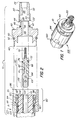
- the connector 10 generally comprises several component parts which are shown in a semi-exploded view.
- the component parts include a nose assembly 20 , an outer conductor contact body 40 , an center conductor contact assembly 60 , and an outer conductor contact securing assembly 80 .
- the method of the present invention uses, a cable connector which is provided with seals or moisture barriers at all critical interfaces between its component parts.
- the method of the present invention uses a center conductor contact assembly that is fitted with a press fit insulative bead which provides internal moisture barriers to dramatically improve resistance to internal moisture migration.
- Connectors having the below described structure including a press fit bead have been used in pressurized cable applications wherein the cable is pressurized so as to pressurize antenna elements for structural rigidity purposes.
- the nose assembly 20 of the connector 10 is generally cylindrically shaped and includes a body coupling end 22 and an antenna coupling end 24 .
- the nose includes a varying diameter bore 26 extending from the body coupling end 22 to the antenna coupling end 24 .
- An O-ring seal receiving recess 28 is provided at the body coupling end 22 .
- a portion 30 of the interior diameter of the nose assembly 20 adjacent to the O-ring seal receiving recess 28 , is threaded.
- the nose assembly 20 also includes an exterior threaded portion 32 , between the body coupling end 22 and the antenna coupling end 24 .
- Connector body 40 is generally cylindrically shaped with a varying outside diameter along its length.
- the connector body 40 includes a threaded outer conductor coupling end 42 , a threaded nose assembly coupling end 44 with an O-ring seal receiving surface 45 , and a varying diameter cylindrical bore 46 extending from the outer conductor coupling end 42 to the nose assembly coupling end 44 .
- An insulative bead receiving portion 48 of the bore 46 is dimensioned to snugly receive an center conductor insulator bead 62 .
- the connector body 40 also includes an O-ring seal receiving recess 50 in which an O-ring seal 52 resides.
- the center conductor contact assembly 60 also generally cylindrically shaped, includes a metal center conductor contact body 64 having a threaded shank 66 dimensioned to fit within the center conductor of an RF cable, a bead receiving shaft 68 and a diametric bore 69 .
- the threaded shank 66 of the metal center conductor contact body 64 provides electrical connection to the center conductor of the RF cable.
- a pin 70 for connection to another coaxial connector or an antenna, such as a type NF contact, is attached to the bead receiving shaft 68 and may be held in place by solder or any other suitable securing means such as threading, for example.
- the contact assembly 60 also includes the previously mentioned cylindrically shaped bead 62 having a lengthwise bore 61 therein and an O-ring receiving recess 72 on its outer surface in which an O-ring seal 74 may reside.
- the bead 62 is fabricated from virgin white poly-tetra-fluoro-ethylene, commonly known under the trademark TEFLON. Other insulative materials may be used for the bead 62 provided such materials have adequate electrical insulating properties.
- the diameter of the lengthwise bore of the TEFLON bead 62 is dimensioned to lit as snugly as possible to the bead receiving shaft 68 .
- the bead 62 is dimensioned such that it must be press fit onto the bead receiving shaft 68 .
- a moisture barrier between the bead 62 and the bead receiving shaft 68 is created by the tight press fit between the bead and shaft.
- FIG. 4 illustrates an alternative embodiment of the cylindrically shaped bead 62 ' where a second O-ring receiving recess 71 is positioned within the lengthwise bore 61 for receipt of an O-ring 73 .
- the diameter of the central bore is dimensioned to slide over receiving shaft 68 , with O-ring 73 providing the moisture barrier therebetween.
- the outer conductor contact securing assembly 80 comprises a collet 82 which is generally angularly shaped and includes a cable jacket end 83 .
- the collet 82 is used to grasp the outer conductor and make electrical contact therewith.
- the inside diameter of the collet 82 is shaped to match the ribbed outer conductor 102 of a cable 100 having a foam dielectric 103 .
- the collet 82 comprises two collet halves which are positioned bound the outer conductor 102 of the cable 100 and held together by a retaining spring or clip 83 substantially surrounding the collet halves.
- An example of two collet halves held together by a retaining spring is shown in U. S. Patent 5,454,735, assigned to the assignee of the present invention, and the description therein is incorporated by reference.
- the assembly 80 includes a back nut 84 which has a body coupling end 86 , a collet abutting end 88 , and a threaded portion 90 between the body coupling end 86 and the collet contacting end 88 .
- the assembly 80 also includes an O-ring seal receiving surface 87 adjacent to the body coupling end 86 to which O-ring 52 may be positioned against.
- the assembly 80 also includes an O-ring seal 90 positioned between the outer conductor 102 of the cable and the back nut 88 .
- FIG. 2 illustrates the connector 10 in the fully assembled, externally and internally moisture migration proof site suitable for use in severely varying ambient conditions.
- the connector 10 is assembled and attached to the cable 100 in a conventional manner so as to form an unpressurized radio frequency transmission system 105 .
- a sufficient length of the outer protective jacket 103 of the cable 100 is stripped off, exposing a length of outer conductor 102 .
- the cable 100 is inserted through the back nut 84 , and through the O-ring seal 90 which has an inside diameter approximately the same size as the outside diameter of the outer conductor 102 .
- the collet 82 is attached to the exposed outer conductor 102 so that one end is adjacent to the O-ring seal 90 and the other end is adjacent to the end of the cable 100 .
- the center conductor threaded shank 66 is threaded to the center conductor 101 .
- a rod (not shown) may be inserted into the diametric bore 69 to facilitate threading of the threaded shank 66 of the center conductor into the center conductor 101 of the cable 100 since the metal conductor 64 is generally cylindrically shaped.
- the O-ring groove 72 in the bead 62 is fitted with the O-ring seal 74 .
- O-ring seal 52 is placed in O-ring seal receiving groove 50 and the body 40 is securely threaded to the back nut's threaded portion 88 .
- the O-ring seal 52 is snugly positioned between back net 84 and the O-ring seal receiving groove 50 and forms a tight, moisture proof seal.
- the insulative bead 62 resides in the bead receiving portion 48 of bore 46 .
- a moisture barrier between the bead 62 and the bead receiving portion 48 of bore 46 is formed by O-ring 74 positioned between recess 72 and bead receiving portion 48 .
- a moisture barrier between the bead 62 and the center conductor's bead receive shaft 68 is provided by the press fitting of the bead 62 on the shaft 68 , or for the alternative bead embodiment 62 ' shown in FIG. 4, by O-ring 73 . It has been found that the two aforementioned moisture barriers provide greatly improved internal moisture migration resistance in an unpressurized coaxial cable.
- O-ring seal 47 is positioned on O-ring receiving surface 45 of the body, the nose assembly 20 is securely coupled to the body 40 .
- O-ring seal 47 positioned between the nose assembly 20 and the body 40 , provides a moisture seal for the joint therebetween.
- FIG. 1 illustrates the appearance of the assembled connector 10 which may be used in the method of the present invention.
- a heat shrinkable sleeve 120 of sufficient length may be fitted over the connector so as to cover the above mentioned joints between the body 40 and the back nut 84 , and between the back nut 84 and the cable jacket 103 . Once sleeve 120 is fitted over the connector 10 , heat may be applied to the sleeve 120 to shrink the diameter of the sleeve 120 so as to provide a continuous, tight fitting exterior moisture barrier over the above mentioned joints.
- the present invention provides a moisture migration proof radio frequency transmission system formed by foam dielectric coaxial cable in combination with the above-described connector.
- the present invention also describes a method for forming a moisture proof radio frequency transmission system and although such a system and method has been described with respect to one or more particular embodiments, it will be understood that other embodiments of the present invention, such as the type of coaxial cable used and the like, may be employed without departing from the spirit and scope of the present invention. Hence, the present invention is deemed limited only by the appended claims and the reasonable interpretation thereof.
Landscapes
- Connector Housings Or Holding Contact Members (AREA)
- Coupling Device And Connection With Printed Circuit (AREA)
Applications Claiming Priority (2)
| Application Number | Priority Date | Filing Date | Title |
|---|---|---|---|
| US54380895A | 1995-10-16 | 1995-10-16 | |
| US543808 | 1995-10-16 |
Publications (2)
| Publication Number | Publication Date |
|---|---|
| EP0768736A2 true EP0768736A2 (de) | 1997-04-16 |
| EP0768736A3 EP0768736A3 (de) | 1998-10-28 |
Family
ID=24169627
Family Applications (1)
| Application Number | Title | Priority Date | Filing Date |
|---|---|---|---|
| EP96114695A Withdrawn EP0768736A3 (de) | 1995-10-16 | 1996-09-13 | Gegen kriechende Feuchtigkeit abgesichertes druckloses Radiofrequenzen übertragendes System und Methode |
Country Status (3)
| Country | Link |
|---|---|
| EP (1) | EP0768736A3 (de) |
| AU (1) | AU6801796A (de) |
| NZ (1) | NZ299557A (de) |
Cited By (6)
| Publication number | Priority date | Publication date | Assignee | Title |
|---|---|---|---|---|
| EP1160932A1 (de) * | 2000-06-02 | 2001-12-05 | Institut Francais Du Petrole | Wasserdichte elektrische Verbindungsvorrichtung für Elektroden mit geschirmten Kable und System für Petrophysicalische Messungen |
| CN100399630C (zh) * | 2003-02-13 | 2008-07-02 | 安德鲁公司 | 同轴电缆连接器和电缆连接器系统 |
| WO2009029210A1 (en) * | 2007-08-24 | 2009-03-05 | Corning Gilbert Inc. | Coaxial cable connector |
| CN102148445A (zh) * | 2010-12-11 | 2011-08-10 | 中航光电科技股份有限公司 | 射频同轴连接器 |
| WO2012099756A1 (en) * | 2011-01-18 | 2012-07-26 | Advanced Bionics Ag | Moisture resistant headpieces and implantable cochlear stimulation systems including the same |
| CN105576592A (zh) * | 2015-08-27 | 2016-05-11 | 顾钰锋 | 电缆接头防潮罩 |
Family Cites Families (5)
| Publication number | Priority date | Publication date | Assignee | Title |
|---|---|---|---|---|
| US3854789A (en) * | 1972-10-02 | 1974-12-17 | E Kaplan | Connector for coaxial cable |
| US5137470A (en) * | 1991-06-04 | 1992-08-11 | Andrew Corporation | Connector for coaxial cable having a helically corrugated inner conductor |
| DE9201175U1 (de) * | 1992-01-31 | 1992-04-16 | Spinner, Georg, Dr.-Ing., 8152 Feldkirchen-Westerham | Koaxiale Steckverbindung |
| US5454735A (en) * | 1994-04-19 | 1995-10-03 | Radio Frequency Systems, Inc. | Severable radio frequency coaxial cable connectors having minimal signal degradation |
| US5439386A (en) * | 1994-06-08 | 1995-08-08 | Augat Inc. | Quick disconnect environmentally sealed RF connector for hardline coaxial cable |
-
1996
- 1996-09-13 EP EP96114695A patent/EP0768736A3/de not_active Withdrawn
- 1996-10-04 AU AU68017/96A patent/AU6801796A/en not_active Abandoned
- 1996-10-11 NZ NZ299557A patent/NZ299557A/en unknown
Cited By (13)
| Publication number | Priority date | Publication date | Assignee | Title |
|---|---|---|---|---|
| EP1160932A1 (de) * | 2000-06-02 | 2001-12-05 | Institut Francais Du Petrole | Wasserdichte elektrische Verbindungsvorrichtung für Elektroden mit geschirmten Kable und System für Petrophysicalische Messungen |
| FR2809821A1 (fr) * | 2000-06-02 | 2001-12-07 | Inst Francais Du Petrole | Dispositif de connexion electrique etanche d'electrodes par cable blinde et systeme pour mesures petrophysiques utilisant le dispositif |
| US6571606B2 (en) * | 2000-06-02 | 2003-06-03 | Institut Francais Du Petrole | Device intended for sealed electric connection of electrodes by shielded cables and system for petrophysical measurement using the device |
| CN100399630C (zh) * | 2003-02-13 | 2008-07-02 | 安德鲁公司 | 同轴电缆连接器和电缆连接器系统 |
| WO2009029210A1 (en) * | 2007-08-24 | 2009-03-05 | Corning Gilbert Inc. | Coaxial cable connector |
| US7537482B2 (en) | 2007-08-24 | 2009-05-26 | Corning Gilbert Inc. | Coaxial cable connector |
| CN102148445A (zh) * | 2010-12-11 | 2011-08-10 | 中航光电科技股份有限公司 | 射频同轴连接器 |
| CN102148445B (zh) * | 2010-12-11 | 2014-02-12 | 中航光电科技股份有限公司 | 射频同轴连接器 |
| WO2012099756A1 (en) * | 2011-01-18 | 2012-07-26 | Advanced Bionics Ag | Moisture resistant headpieces and implantable cochlear stimulation systems including the same |
| CN106878838A (zh) * | 2011-01-18 | 2017-06-20 | 领先仿生公司 | 防潮耳机和包括防潮耳机的可植入耳蜗刺激系统 |
| CN106878838B (zh) * | 2011-01-18 | 2019-04-30 | 领先仿生公司 | 防潮耳机和包括防潮耳机的可植入耳蜗刺激系统 |
| CN105576592A (zh) * | 2015-08-27 | 2016-05-11 | 顾钰锋 | 电缆接头防潮罩 |
| CN105576592B (zh) * | 2015-08-27 | 2017-08-01 | 郑香桂 | 电缆接头防潮罩 |
Also Published As
| Publication number | Publication date |
|---|---|
| EP0768736A3 (de) | 1998-10-28 |
| AU6801796A (en) | 1997-04-24 |
| NZ299557A (en) | 1998-05-27 |
Similar Documents
| Publication | Publication Date | Title |
|---|---|---|
| CA1242008A (en) | Coaxial cable connector | |
| US7241164B2 (en) | Termination assembly for mini-coaxial cable having color-coded insulator | |
| KR100461981B1 (ko) | 경선동축케이블용 커넥터 | |
| EP0929917B1 (de) | Fernsehenergie stecker über kabelfernsehenkabel | |
| US4547623A (en) | Cable shield grounding apparatus | |
| US5769662A (en) | Snap together coaxial cable connector for use with polyethylene jacketed cable | |
| US4690482A (en) | High frequency, hermetic, coaxial connector for flexible cable | |
| US5408743A (en) | Process for connecting an electric cable having a light metal core to a standardized end element | |
| CA1133998A (en) | Angled coaxial assembly and a method of manufacturing same | |
| US3085138A (en) | Electrical connector | |
| CA2376462C (en) | Connector for different sized coaxial cables and related methods | |
| US20050079759A1 (en) | Tuned radio frequency coaxial connector | |
| MY110075A (en) | Connector for coaxial cables. | |
| US20090280668A1 (en) | Connector with deformable Compression Sleeve | |
| US8488290B2 (en) | Protective device | |
| US3543222A (en) | Method and apparatus for coupling to a co-axial cable | |
| US4543548A (en) | Coaxial transmission line having an expandable and contractible bellows | |
| NZ299557A (en) | Radio frequency antenna/coaxial cable connector with seal preventing water migration from antenna centre conductor to cable | |
| EP1642362B1 (de) | Koaxialkontakt | |
| US3377422A (en) | Splice assembly to connect cable ends together | |
| JP2003223943A (ja) | 無機絶縁ケーブルの連結スリーブおよび接続方法 | |
| US6095858A (en) | Coaxial cable connector | |
| US5168280A (en) | Antenna with push-in cable connector | |
| US6441706B1 (en) | Seal for an RF connector | |
| DE3776822D1 (de) | Verbindung fuer zwei koaxialkabel. |
Legal Events
| Date | Code | Title | Description |
|---|---|---|---|
| PUAI | Public reference made under article 153(3) epc to a published international application that has entered the european phase |
Free format text: ORIGINAL CODE: 0009012 |
|
| AK | Designated contracting states |
Kind code of ref document: A2 Designated state(s): BE CH DE DK GB IT LI |
|
| PUAL | Search report despatched |
Free format text: ORIGINAL CODE: 0009013 |
|
| AK | Designated contracting states |
Kind code of ref document: A3 Designated state(s): BE CH DE DK GB IT LI |
|
| STAA | Information on the status of an ep patent application or granted ep patent |
Free format text: STATUS: THE APPLICATION IS DEEMED TO BE WITHDRAWN |
|
| 18D | Application deemed to be withdrawn |
Effective date: 19990401 |