EP0768741A2 - Cellule transportable pour poste transformateur - Google Patents
Cellule transportable pour poste transformateur Download PDFInfo
- Publication number
- EP0768741A2 EP0768741A2 EP96115760A EP96115760A EP0768741A2 EP 0768741 A2 EP0768741 A2 EP 0768741A2 EP 96115760 A EP96115760 A EP 96115760A EP 96115760 A EP96115760 A EP 96115760A EP 0768741 A2 EP0768741 A2 EP 0768741A2
- Authority
- EP
- European Patent Office
- Prior art keywords
- wall
- cell according
- cover
- section
- interior
- Prior art date
- Legal status (The legal status is an assumption and is not a legal conclusion. Google has not performed a legal analysis and makes no representation as to the accuracy of the status listed.)
- Granted
Links
- 238000007373 indentation Methods 0.000 claims description 3
- 230000002787 reinforcement Effects 0.000 claims description 2
- XLYOFNOQVPJJNP-UHFFFAOYSA-N water Substances O XLYOFNOQVPJJNP-UHFFFAOYSA-N 0.000 description 5
- 229910052751 metal Inorganic materials 0.000 description 4
- 239000002184 metal Substances 0.000 description 4
- 238000010276 construction Methods 0.000 description 3
- 238000011161 development Methods 0.000 description 3
- 230000018109 developmental process Effects 0.000 description 3
- 238000009423 ventilation Methods 0.000 description 3
- 238000010616 electrical installation Methods 0.000 description 2
- 241001295925 Gegenes Species 0.000 description 1
- 229910052782 aluminium Inorganic materials 0.000 description 1
- XAGFODPZIPBFFR-UHFFFAOYSA-N aluminium Chemical compound [Al] XAGFODPZIPBFFR-UHFFFAOYSA-N 0.000 description 1
- 230000015572 biosynthetic process Effects 0.000 description 1
- 230000002349 favourable effect Effects 0.000 description 1
- 238000004519 manufacturing process Methods 0.000 description 1
- 238000000034 method Methods 0.000 description 1
- 230000003287 optical effect Effects 0.000 description 1
- 238000005192 partition Methods 0.000 description 1
- 230000000149 penetrating effect Effects 0.000 description 1
- 230000000284 resting effect Effects 0.000 description 1
- 229910001220 stainless steel Inorganic materials 0.000 description 1
- 239000010935 stainless steel Substances 0.000 description 1
- 230000001502 supplementing effect Effects 0.000 description 1
- 230000007704 transition Effects 0.000 description 1
- 230000000007 visual effect Effects 0.000 description 1
Images


Classifications
-
- H—ELECTRICITY
- H02—GENERATION; CONVERSION OR DISTRIBUTION OF ELECTRIC POWER
- H02B—BOARDS, SUBSTATIONS OR SWITCHING ARRANGEMENTS FOR THE SUPPLY OR DISTRIBUTION OF ELECTRIC POWER
- H02B7/00—Enclosed substations, e.g. compact substations
- H02B7/06—Distribution substations, e.g. for urban network
Definitions
- the invention relates to a transportable room cell in the form of a substation partially lowered into the ground, an interior for a transformer, for high, medium and / or low-voltage switching devices or the like.
- Transformer station with four wall parts, which may be monolithically connected to a base plate. So they are cast on - as well as with a roof.
- the cell interior of a transformer station of this type is divided into a transformer compartment for receiving the transformer with an oil pan underneath, and a switch compartment for receiving those high, medium or low voltage switching devices.
- Such stations are factory-equipped as so-called finishing stations with the necessary switching devices - with the exception of the transformer -, mounting rails and the complete electrical installation including earthing, so that at the construction site only the transformer, usually mounted on wheels, is mounted on rails in the station must be inserted into the interior of the cell.
- the latter is accessible thanks to two horizontally pivoting doors that are part of a side wall made of profiles and panels.
- DE-A-31 10 304 discloses a room cell as an electrical network station which has lower side walls and an intermediate floor resting thereon.
- a partition wall extends upwards from the intermediate floor as a pressure sign, which is drawn into the interior of the network station at a predetermined distance and is guided to just below the roof plate of the station.
- the inventor has set itself the goal of producing, equipping and using such a small station in a simple and inexpensive manner.
- the adaptability to different types of electrical installation elements is to be facilitated and operational reliability is to be increased.
- the roofing consists of two lids which can be pivoted separately about joints which are parallel to one another, one of which is articulated in the region of a gutter support which overlaps the interior of the cell and has an apron section angled from the plane of a ridge section of the lid; the latter forms the upper part of a wall part in the closed state of the transformer station, in particular on the front wall.
- the room cell according to the invention provides that at least one surface offered by the cover (s) or the ridge section is inclined at an angle of inclination from the horizontal. This angle of inclination is preferably about 2 ° to 8 °, more preferably about 3 ° to 5 °.
- the apron section according to the invention is further preferred by an edge profile or the like. Element fixed on the ridge section.
- the apron section of the cover is preferably folded from the plane of the ridge section - and is then in one piece with it.
- the angle between the ridge section and the apron section of the cover should be greater than 90 ° in order to ensure its alignment with the wall part to be supplemented on the one hand and the inclination of the ridge section on the other hand.
- the formed from a plate - preferably from a metal plate such as aluminum sheet - is equipped with a in the closed position approximately parallel to the wall parts and to these outside at a distance, the wall parts overlapping cover edge. In a preferred embodiment, this is folded out of the plane of the cover, that is to say also in one piece with it.
- the edge of the lid and subsequent lid delimit the edges of the wall parts with these flow paths for air circulation for the cell interior.
- the cover edge of a rear cover which runs parallel to that of a front cover, encloses an angle of more than 90 ° therewith.
- hinges are attached so that the closing process is simplified.
- the hinge axis of the (rear) cover hinged to a wall part - in particular the rear wall - runs below the level of the upper edge of the wall part, but preferably at a (greater) distance below this upper edge within the edge of the cover. You can do this in cutouts for receiving hinge tabs may be provided on the rear wall of the room cell.
- the hinge axis of the joint arranged in the region of the channel support for the two-part cover is above the channel opening.
- the hinge bracket is also fixed parallel to the boot lid and is curved with its free end having an eye for the hinge axis.
- the hinge bracket can also be fixed on a rail-like support of the rear wall.
- this or the ridge section is provided parallel to its side wall within the cell interior at a distance from the wall part with a reinforcement profile to which one end of at least one energy accumulator, in particular a gas spring, is articulated and which is at the other end supported on the adjacent wall part.
- the latter offers a cross-sectionally horizontal shoulder; above the upper edge of the front wall which can be supplemented by the apron section, this shoulder is formed in one embodiment into the inner surface of the side wall; it runs horizontally near that top edge and below the channel support and inclined in between.
- below the top edge of the side wall in the inner surface of the shoulder is part of an indentation that runs horizontally from the front wall and ends behind the gutter support.
- the shoulder at least partially carries an undercut profile as a connecting element for the gas spring or the like.
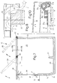
- a medium-voltage system 18 is arranged on the inside near the front wall 14 with a length a of 2,500 mm and a viewing height b of approximately 150 mm, next to this a low-voltage system 19 and behind these two a transformer 20.
- front wall 14 At the front wall 14 are parallel side walls 22 of length e of 2,300 mm, which are connected by a rear wall 24; Side walls 22 and rear wall 24 are cast together with the front wall 14 and a base plate 26 monolithically from concrete.
- the total height f of the side and rear walls 22, 24 corresponds approximately to that side length e.
- the transformer station 10 is closed by a front cover 28 and a rear cover 30 supplementing it, both of which - as is particularly clear from FIG. 5 - can be opened in the same direction towards the rear wall 24; hinges 32 for the boot lid 30 are attached to this.
- the front cover 28 is produced from a single light metal plate which is divided at a scanting angle w of somewhat more than 90 ° into a ridge section 35 and a apron section 36 which is inclined downwards from the area of the hinges 32 to a front edge 34; the latter complements the front wall 14 in the closed state.
- the ridge section 35 is connected by the hinges 32 to a gutter support 38 which crosses the station interior 11 and which in an embodiment of FIG. 7 has a threshold 27 and cast monolithically with the base plate 26 runs at an average distance i of approximately 1,100 mm from the front wall 14.
- Both covers 28, 30 are supported by gas springs 29 on the side walls 24 and are easy to move relative to them.
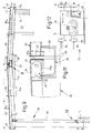
- the ventilation takes place on the one hand by means of passages 37 at the lower edge of the skirt section 36, and on the other hand below the ridge section 35 according to the arrows y. These symbolize, for example in FIG. 8, the air flows between the trunk lid 30 and the upper edge 23 of the side wall 22, the thickness k of which here measures 100 mm.
- the exemplary embodiment in FIG. 9 contains an indentation 21 with an approximately horizontal shoulder 50 h and a length n of 1,200 mm in the concrete of the side wall 22 with an inserted channel support 38.
- the angles of inclination t, t 1 of approximately 3 ° to 5 ° are particularly clear two covers or cover sections 30, 35 - and thus their cover surfaces 30 a , 35 a - recognizable.
- the channel support 38 may be used for draining water penetrating between the two lids 28, 30; the interior of the channel 39 engages under the roof gap 52 existing between the two lids 28, 30.
- the front cover 28 - like that of FIG. 7 - is made of two separate parts 35, 36; the apron section 36 hangs firmly on a rectangular profile 54 which is connected to the ridge section 35.
- the width q of this ridge section 35 measures 1.325 mm, so it is somewhat longer than that concrete cut length n.
- Fig. 10 shows the hinge point X of FIG. 9 with on the upper edge 23 of the rear wall 24 - with the interposition of a stainless steel rail 25 - horizontally on an intermediate plate 25 a fixed hinge bracket 31 a .
- This is curved outside the intermediate plate 25 a and below the surface of the intermediate plate - plane E - a horizontal eye 32 a for the lid-side hinge axis 33.
- the hinge bracket 31 a ends above an edge 46 e of the rear vertical edge 46.
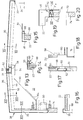
- the front cover 28 of FIG. 13 is in turn bent from a single light metal plate 56.
- the vertical edge 46 in the region of the channel opening is of reduced height z (see FIG. 46 a in FIG. 11).
- An inclined shoulder 50 runs in the side wall 22 towards the front wall 14, which can be seen particularly well in FIG. 4. Below this, a pocket-like edge incision 60 is provided, which is closed by a side cover 62. Undercut profiles 64 with receiving groove 65 run on the inclined shoulder 50.
- FIGS. 13 to 19 in particular show the flow space for the ventilation delimited by the corresponding wall parts 14, 22, 24 on the one hand and the covers 28, 30 and cover edges 46, which are at a distance from one another (arrow y in FIG. 14).
- the apron section 36 of both exemplary embodiments shown contains a compact lock 72 for releasable connection to the underlying front wall 14, as is indicated in FIG. 12.
- a rotary handle 76 is mounted on a lock plate 74, next to it a lock case 78 with a PVC rosette 80 for a lock cylinder can be seen.
- a locking bracket 82 movable in the pushing direction x is assigned as a bearing for a pair of locking rods 84; their guides on the apron section are neglected in the drawing.
- space cells 10 described can be arranged next to one another and produced in one piece, as shown in FIG. 21 using a double cell 10 a , the length a 1 of which is slightly more than 400 cm and the width e of which is approximately 230 cm.
Landscapes
- Engineering & Computer Science (AREA)
- Power Engineering (AREA)
- Laying Of Electric Cables Or Lines Outside (AREA)
- Casings For Electric Apparatus (AREA)
- Housings And Mounting Of Transformers (AREA)
- Transmitters (AREA)
- Tents Or Canopies (AREA)
Applications Claiming Priority (4)
| Application Number | Priority Date | Filing Date | Title |
|---|---|---|---|
| DE19538268 | 1995-10-13 | ||
| DE19538268 | 1995-10-13 | ||
| DE19614593A DE19614593A1 (de) | 1995-10-13 | 1996-04-12 | Transportable Raumzelle als Umspannstation |
| DE19614593 | 1996-04-12 |
Publications (3)
| Publication Number | Publication Date |
|---|---|
| EP0768741A2 true EP0768741A2 (fr) | 1997-04-16 |
| EP0768741A3 EP0768741A3 (fr) | 1997-08-20 |
| EP0768741B1 EP0768741B1 (fr) | 2001-08-01 |
Family
ID=26019484
Family Applications (1)
| Application Number | Title | Priority Date | Filing Date |
|---|---|---|---|
| EP96115760A Expired - Lifetime EP0768741B1 (fr) | 1995-10-13 | 1996-10-02 | Cellule transportable pour poste transformateur |
Country Status (3)
| Country | Link |
|---|---|
| EP (1) | EP0768741B1 (fr) |
| AT (1) | ATE203856T1 (fr) |
| PL (1) | PL180976B1 (fr) |
Cited By (7)
| Publication number | Priority date | Publication date | Assignee | Title |
|---|---|---|---|---|
| EP0942442A3 (fr) * | 1998-03-13 | 2000-12-06 | EnBW Badenwerk AG | Poste transformateur à construction compacte |
| RU2219631C1 (ru) * | 2002-12-25 | 2003-12-20 | Шастик Валерий Филиппович | Блочная распределительная трансформаторная подстанция |
| WO2004042171A1 (fr) * | 2002-11-06 | 2004-05-21 | Twelcon Electronica, S.L. | Centre de transformation urbain specialise |
| EP1500757A1 (fr) | 2003-07-23 | 2005-01-26 | Prefabricados Uniblok, S.A. | Construction préfabriquée avec couverture passable pour des applications industrielles |
| WO2007140712A1 (fr) * | 2006-06-01 | 2007-12-13 | Junming Feng | Équipement de puissance avec interaction avec des informations et fonction de média publicitaire et procédé d'application de celui-ci |
| CN102263381A (zh) * | 2011-08-11 | 2011-11-30 | 浙江安可电气科技有限公司 | 半埋式箱式变电站的下箱体结构 |
| US10522801B2 (en) | 2015-09-11 | 2019-12-31 | Younicos, Inc. | Modular energy storage system |
Families Citing this family (2)
| Publication number | Priority date | Publication date | Assignee | Title |
|---|---|---|---|---|
| RU2271594C1 (ru) * | 2004-07-13 | 2006-03-10 | Юрий Валентинович Бураков | Электроустановка |
| PL216600B1 (pl) | 2009-05-25 | 2014-04-30 | ABB Spółka z ograniczoną odpowiedzialnością | Zestaw do konstrukcji obudowy dla modułowych rozdzielnic podstacji energetycznych rozdziału wtórnego |
Family Cites Families (8)
| Publication number | Priority date | Publication date | Assignee | Title |
|---|---|---|---|---|
| DE2401532C3 (de) * | 1974-01-14 | 1979-09-13 | Rudolf Dipl.-Ing. 7000 Stuttgart Koerber | Begehbare Mittelspannungsnetzstation in Niedrigbauweise |
| FR2341972A1 (fr) * | 1976-02-17 | 1977-09-16 | Merlin Gerin | Poste prefabrique semi-enterre de transformation moyenne tension-basse tension |
| DE2706959A1 (de) * | 1977-02-18 | 1978-08-24 | Gervin Josef Mueller | Teilweise in das erdreich einsenkbare, transportable energieverteilungs- und/oder erzeugungsstation |
| FR2417196A1 (fr) * | 1978-02-08 | 1979-09-07 | Denizet Rene | Cabine de transformation electrique |
| US4644095A (en) * | 1985-02-14 | 1987-02-17 | Western Power Products, Inc. | Enclosure for outdoor, ground level mounted communication equipment |
| DE8519621U1 (de) * | 1985-07-06 | 1985-10-03 | Betonbau GmbH, 6833 Waghäusel | Transportable Umspannstation |
| US4821143A (en) * | 1987-10-30 | 1989-04-11 | Cooper Power Systems, Inc. | Switchgear enclosure with improved supporting frame and improved access door |
| CH682961A5 (fr) * | 1990-04-12 | 1993-12-15 | Bsa Ingenieurs Conseils | Station transformatrice enterrée au moins partiellement. |
-
1996
- 1996-10-02 EP EP96115760A patent/EP0768741B1/fr not_active Expired - Lifetime
- 1996-10-02 AT AT96115760T patent/ATE203856T1/de not_active IP Right Cessation
- 1996-10-11 PL PL96316493A patent/PL180976B1/pl unknown
Cited By (8)
| Publication number | Priority date | Publication date | Assignee | Title |
|---|---|---|---|---|
| EP0942442A3 (fr) * | 1998-03-13 | 2000-12-06 | EnBW Badenwerk AG | Poste transformateur à construction compacte |
| WO2004042171A1 (fr) * | 2002-11-06 | 2004-05-21 | Twelcon Electronica, S.L. | Centre de transformation urbain specialise |
| US7715175B2 (en) | 2002-11-06 | 2010-05-11 | Twelcon Electronica, S.L. | Special urban transformation center |
| RU2219631C1 (ru) * | 2002-12-25 | 2003-12-20 | Шастик Валерий Филиппович | Блочная распределительная трансформаторная подстанция |
| EP1500757A1 (fr) | 2003-07-23 | 2005-01-26 | Prefabricados Uniblok, S.A. | Construction préfabriquée avec couverture passable pour des applications industrielles |
| WO2007140712A1 (fr) * | 2006-06-01 | 2007-12-13 | Junming Feng | Équipement de puissance avec interaction avec des informations et fonction de média publicitaire et procédé d'application de celui-ci |
| CN102263381A (zh) * | 2011-08-11 | 2011-11-30 | 浙江安可电气科技有限公司 | 半埋式箱式变电站的下箱体结构 |
| US10522801B2 (en) | 2015-09-11 | 2019-12-31 | Younicos, Inc. | Modular energy storage system |
Also Published As
| Publication number | Publication date |
|---|---|
| EP0768741A3 (fr) | 1997-08-20 |
| PL180976B1 (pl) | 2001-05-31 |
| PL316493A1 (en) | 1997-04-14 |
| EP0768741B1 (fr) | 2001-08-01 |
| ATE203856T1 (de) | 2001-08-15 |
Similar Documents
| Publication | Publication Date | Title |
|---|---|---|
| EP0563436A1 (fr) | Bâtiment transportable et sa méthode de construction | |
| EP0878808B1 (fr) | Station de transformation électrique | |
| EP0768741A2 (fr) | Cellule transportable pour poste transformateur | |
| DE29606617U1 (de) | Netzstation in Form einer Raumzelle | |
| EP0465935A1 (fr) | Module de bâtiment | |
| EP0343356B1 (fr) | Poste de transformation ou pareil contenant des orifices de ventilation d'un courant d'air | |
| DE69603230T2 (de) | Gehäuse zur Aufnahme insbesondere elektrischer Geräte | |
| DE19614593A1 (de) | Transportable Raumzelle als Umspannstation | |
| DE2401531A1 (de) | In das erdreich absenkbare mittelspannungsnetzstation aus betonfertigteilen in niedrigbauweise | |
| DE69506460T2 (de) | Transformatorenstation | |
| DE29718692U1 (de) | Raumzelle, insbesondere für Mehrzweckbauwerke | |
| DE29702415U1 (de) | Gehäuse für Umspannstationen | |
| DE9206780U1 (de) | Lüftertür | |
| DE4307478C2 (de) | Vorrichtung zum Verschließen einer Wandöffnung, insbesondere eines Zuganges für eine Schaltstation | |
| DE10336910A1 (de) | Transformatorenstation | |
| DE4213146A1 (de) | Lüftertür | |
| DE4310290A1 (de) | Transportable Raumzelle als Umspannstation | |
| DE19710593A1 (de) | Transportable Raumzelle als Umspannstation | |
| DE19752153B4 (de) | Vorrichtung zur Herstellung einer tansportablen Raumzelle als Umspannstation | |
| DE29604868U1 (de) | Transportable Raumzelle als Umspannstation | |
| DE19649238B4 (de) | Vorrichtung zum Verschließen eines Wanddurchbruches, insbesondere eines Zuganges, einer Schaltstation | |
| DE10009013A1 (de) | Transportable Raumzelle als Umspannstation | |
| EP0910146A1 (fr) | Boítier | |
| DE3524539C2 (de) | Kabelverzweigerschrank | |
| DE10008727B4 (de) | Umspannstation |
Legal Events
| Date | Code | Title | Description |
|---|---|---|---|
| PUAI | Public reference made under article 153(3) epc to a published international application that has entered the european phase |
Free format text: ORIGINAL CODE: 0009012 |
|
| AK | Designated contracting states |
Kind code of ref document: A2 Designated state(s): AT BE DE FR |
|
| AX | Request for extension of the european patent |
Free format text: LT;LV;SI |
|
| PUAL | Search report despatched |
Free format text: ORIGINAL CODE: 0009013 |
|
| RBV | Designated contracting states (corrected) |
Designated state(s): AT BE DE FR |
|
| AK | Designated contracting states |
Kind code of ref document: A3 Designated state(s): AT BE CH DE DK ES FR GB GR IE IT LI LU MC NL PT SE |
|
| AX | Request for extension of the european patent |
Free format text: LT;LV;SI |
|
| 17P | Request for examination filed |
Effective date: 19970918 |
|
| 17Q | First examination report despatched |
Effective date: 19981106 |
|
| GRAG | Despatch of communication of intention to grant |
Free format text: ORIGINAL CODE: EPIDOS AGRA |
|
| GRAG | Despatch of communication of intention to grant |
Free format text: ORIGINAL CODE: EPIDOS AGRA |
|
| GRAH | Despatch of communication of intention to grant a patent |
Free format text: ORIGINAL CODE: EPIDOS IGRA |
|
| GRAH | Despatch of communication of intention to grant a patent |
Free format text: ORIGINAL CODE: EPIDOS IGRA |
|
| GRAA | (expected) grant |
Free format text: ORIGINAL CODE: 0009210 |
|
| AK | Designated contracting states |
Kind code of ref document: B1 Designated state(s): AT BE DE FR |
|
| REF | Corresponds to: |
Ref document number: 203856 Country of ref document: AT Date of ref document: 20010815 Kind code of ref document: T |
|
| REF | Corresponds to: |
Ref document number: 59607406 Country of ref document: DE Date of ref document: 20010906 |
|
| PG25 | Lapsed in a contracting state [announced via postgrant information from national office to epo] |
Ref country code: AT Free format text: LAPSE BECAUSE OF NON-PAYMENT OF DUE FEES Effective date: 20011002 |
|
| PG25 | Lapsed in a contracting state [announced via postgrant information from national office to epo] |
Ref country code: BE Free format text: LAPSE BECAUSE OF NON-PAYMENT OF DUE FEES Effective date: 20011031 |
|
| EN | Fr: translation not filed | ||
| BERE | Be: lapsed |
Owner name: BETONBAU G.M.B.H. Effective date: 20011031 |
|
| EN | Fr: translation not filed |
Free format text: BO 01/52 PAGES: 283, IL Y A LIEU DE SUPPRIMER: LA MENTION DE LA NON REMISE. LA REMISE EST PUBLIEE DANS LE PRESENT BOPI. |
|
| ET | Fr: translation filed | ||
| PLBE | No opposition filed within time limit |
Free format text: ORIGINAL CODE: 0009261 |
|
| STAA | Information on the status of an ep patent application or granted ep patent |
Free format text: STATUS: NO OPPOSITION FILED WITHIN TIME LIMIT |
|
| 26N | No opposition filed | ||
| PGFP | Annual fee paid to national office [announced via postgrant information from national office to epo] |
Ref country code: DE Payment date: 20040728 Year of fee payment: 9 |
|
| PGFP | Annual fee paid to national office [announced via postgrant information from national office to epo] |
Ref country code: FR Payment date: 20041020 Year of fee payment: 9 |
|
| PG25 | Lapsed in a contracting state [announced via postgrant information from national office to epo] |
Ref country code: DE Free format text: LAPSE BECAUSE OF NON-PAYMENT OF DUE FEES Effective date: 20060503 |
|
| PG25 | Lapsed in a contracting state [announced via postgrant information from national office to epo] |
Ref country code: FR Free format text: LAPSE BECAUSE OF NON-PAYMENT OF DUE FEES Effective date: 20060630 |
|
| REG | Reference to a national code |
Ref country code: FR Ref legal event code: ST Effective date: 20060630 |