EP0768779A2 - Unterdrückung von Verzerrungen und Interferenz in Kommunikationssystemen mit mehrfachem Zugriff - Google Patents
Unterdrückung von Verzerrungen und Interferenz in Kommunikationssystemen mit mehrfachem Zugriff Download PDFInfo
- Publication number
- EP0768779A2 EP0768779A2 EP96116078A EP96116078A EP0768779A2 EP 0768779 A2 EP0768779 A2 EP 0768779A2 EP 96116078 A EP96116078 A EP 96116078A EP 96116078 A EP96116078 A EP 96116078A EP 0768779 A2 EP0768779 A2 EP 0768779A2
- Authority
- EP
- European Patent Office
- Prior art keywords
- interference
- signal
- received signal
- modified
- sequence
- Prior art date
- Legal status (The legal status is an assumption and is not a legal conclusion. Google has not performed a legal analysis and makes no representation as to the accuracy of the status listed.)
- Withdrawn
Links
- 230000001629 suppression Effects 0.000 title claims abstract description 27
- 238000004891 communication Methods 0.000 title abstract description 12
- 238000000034 method Methods 0.000 claims abstract description 30
- 230000004044 response Effects 0.000 claims description 16
- 230000006978 adaptation Effects 0.000 claims description 11
- 238000001914 filtration Methods 0.000 claims description 10
- 238000001228 spectrum Methods 0.000 claims description 7
- 238000012549 training Methods 0.000 claims description 3
- 230000005540 biological transmission Effects 0.000 abstract description 7
- 230000003044 adaptive effect Effects 0.000 description 8
- 238000005192 partition Methods 0.000 description 7
- 230000006735 deficit Effects 0.000 description 4
- 238000010586 diagram Methods 0.000 description 4
- 238000011144 upstream manufacturing Methods 0.000 description 4
- 238000001514 detection method Methods 0.000 description 3
- 239000002243 precursor Substances 0.000 description 3
- 238000007493 shaping process Methods 0.000 description 3
- 230000000694 effects Effects 0.000 description 2
- 230000003190 augmentative effect Effects 0.000 description 1
- 238000013461 design Methods 0.000 description 1
- 230000002708 enhancing effect Effects 0.000 description 1
- 239000000835 fiber Substances 0.000 description 1
- 238000002955 isolation Methods 0.000 description 1
- 238000012545 processing Methods 0.000 description 1
- 238000000926 separation method Methods 0.000 description 1
- 238000000638 solvent extraction Methods 0.000 description 1
Images

Classifications
-
- H—ELECTRICITY
- H04—ELECTRIC COMMUNICATION TECHNIQUE
- H04L—TRANSMISSION OF DIGITAL INFORMATION, e.g. TELEGRAPHIC COMMUNICATION
- H04L25/00—Baseband systems
- H04L25/02—Details ; arrangements for supplying electrical power along data transmission lines
- H04L25/03—Shaping networks in transmitter or receiver, e.g. adaptive shaping networks
- H04L25/03006—Arrangements for removing intersymbol interference
- H04L25/03012—Arrangements for removing intersymbol interference operating in the time domain
- H04L25/03019—Arrangements for removing intersymbol interference operating in the time domain adaptive, i.e. capable of adjustment during data reception
- H04L25/03057—Arrangements for removing intersymbol interference operating in the time domain adaptive, i.e. capable of adjustment during data reception with a recursive structure
-
- H—ELECTRICITY
- H04—ELECTRIC COMMUNICATION TECHNIQUE
- H04L—TRANSMISSION OF DIGITAL INFORMATION, e.g. TELEGRAPHIC COMMUNICATION
- H04L25/00—Baseband systems
- H04L25/02—Details ; arrangements for supplying electrical power along data transmission lines
- H04L25/03—Shaping networks in transmitter or receiver, e.g. adaptive shaping networks
- H04L25/03006—Arrangements for removing intersymbol interference
- H04L2025/03433—Arrangements for removing intersymbol interference characterised by equaliser structure
- H04L2025/03439—Fixed structures
- H04L2025/03445—Time domain
- H04L2025/03471—Tapped delay lines
- H04L2025/03484—Tapped delay lines time-recursive
- H04L2025/03503—Tapped delay lines time-recursive as a combination of feedback and prediction filters
Definitions
- the present invention relates generally to detecting a data signal in the presence of distortion and interference in a communication system, and more particularly to adaptive distortion compensation and interference suppression in a multiple-access communication system.
- multiple users communicate with a single central site or headend.
- the headend typically receives bursts of transmissions from the users, and these transmissions are coordinated by the headend according to a Media Access Control (MAC) protocol, which prevents collisions and provides fair and equitable access to the upstream communication link from the users to the headend.
- MAC Media Access Control
- the burst signal received at the headend is distorted because of the imperfections of the transmission medium.
- the headend receiver therefore often includes an equalizer which compensates for the channel distortion.
- the channel distortion is mainly due to micro-reflections in the coaxial cable. Since bursts from different users travel over different physical paths, the channel distortion may be different for each user. Therefore, the headend receiver needs to set-up a new equalizer for each burst received, or remember the equalizer for each user from burst to burst.
- Ingress noise is typically caused by short-wave or amateur radio transmissions which leak into the cable at various points of poor isolation. Often such ingress noise tends to be narrowband relative to the transmission band of the received signal. Narrowband interference suppression schemes may be used to completely eliminate or at least reduce the effects of such narrowband interference.
- Some equalizers which are used to compensate for channel distortion may also help suppress interference due to ingress noise.
- such systems are usually not very effective because they cannot track rapid variations in the interference and at the same time provide effective equalization.
- such systems may add substantial overhead by requiring the receiver to learn the interference characteristics at the start of each burst.
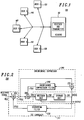
- FIG. 1 is a block diagram of a burst multi-access communication system in which the present invention may be utilized.
- FIG. 2 shows a block diagram of a device for efficiently detecting a data signal in the presence of distortion and interference in accordance with the present invention.
- FIG. 3 shows a block diagram of the device of FIG. 2 further incorporating a preprocessor for efficiently detecting a data signal in the presence of distortion and interference.
- FIG. 4 shows a block diagram of another embodiment of a device for efficiently detecting a data signal in the presence of distortion and interference in accordance with the present invention.
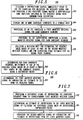
- FIG. 5 is a flow chart of one embodiment of steps of a method of providing efficient detection of a data signal in the presence of distortion and interference in accordance with the present invention.
- FIG. 6 is a flow chart showing one embodiment of steps for providing, by an intersymbol interference (ISI) canceller, the first modified received signal in accordance with the present invention.
- ISI intersymbol interference
- FIG. 7 is a flow chart for one embodiment of steps for providing, by an interference suppresser, the second modified received signal in accordance with the present invention.
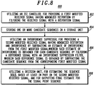
- FIG. 8 is a flow chart showing another embodiment of steps for providing efficient detection of a data signal in the presence of distortion and interference in accordance with the present invention.
- a device and method for detecting a data signal in the presence of distortion and interference which take advantage of the different nature of distortion and interference in the signal received at the headend of a multiple-access communications network such as a HFC network.
- the interference characteristics in such networks are typically user independent.
- the distortion typically depends on which user is transmitting and thus varies from burst to burst.
- the distortion results in the received signal being corrupted by intersymbol interference (ISI), a well known phenomenon.
- ISI intersymbol interference
- the device and method described in the present invention incorporate separate modules for ISI cancellation and interference suppression. This separation allows the adaptive elements associated with the ISI canceller and the interference suppresser to match the distortion and interference characteristics, respectively.
- the adaptive elements may be updated to track the variations of the channel impairments more effectively by taking advantage of the differences between the distortion and the interference.
- the interference suppresser uses the same set of adaptive elements from burst to burst, while the adaptive elements of the ISI canceller are used on a per-burst basis.
- the invention described here is primarily utilized for an HFC cable system, it may also be applied to other types of systems, such as wireless communication systems. In fact, the technique may be applied to any system where it is desirable to deal with distortion and interference separately.
- FIG. 1, numeral 100 shows a multiple-access communication system in which several remote users, (120), (130), (140), (150) and (160) are communicating via a shared medium with a headend, (110), having a receiver and transmitter (170).
- the shared medium may be a HFC cable plant.
- the headend broadcasts to multiple users via a downstream link, while users transmit towards the headend via the upstream link.
- the upstream link is typically of poor quality and suffers from many impairments. Among these impairments, the dominant one is typically ingress noise which may be of significant magnitude relative to the user transmitted signal due to the noise funneling effect.
- the device for distortion compensation and interference suppression of the present invention may be used in a headend receiver which is receiving upstream burst transmissions from the users in the form of modulated digital data signals.
- FIG. 2 shows one embodiment of a device for efficiently detecting a data signal in the presence of distortion and interference in accordance with the present invention.
- the device is utilized for estimating a signal point sequence ⁇ X(k) ⁇ , from a received signal that is ⁇ X(k) ⁇ received in the presence of distortion and interference.
- the ISI canceller generally includes: A) a subtractor (250), operably coupled to receive the received signal and an estimate of ISI from a distortion filter (230), for subtracting, for each candidate sequence, the estimate of ISI from the received signal to generate the first modified received signal; and B) the distortion filter (230), operably coupled to the storage unit (210), for determining the estimate of intersymbol interference in the received signal, wherein said estimate is computed for a given time index n by the distortion filter (230) based on at least one past sample of the candidate sequence.
- the interference suppresser (290; 304; 404) typically includes: A) a first subtractor (260; 360; 460), coupled to receive the first modified signal and an estimate of interference from an interference suppression filter (240), for subtracting the estimate of interference from the first modified signal to generate the second modified signal; B) an interference suppression filter (240; 340; 440), coupled to receive a difference signal, for determining, for each candidate sequence, the estimate of interference, wherein said estimate of interference at a given time index n is computed by the interference suppression filter based on at least one past sample of the difference signal; and C) a second subtractor (270; 370; 470) coupled to receive the first modified signal and to the storage unit, for subtracting, the candidate sequence from the corresponding first modified signal to provide the difference signal for the interference suppression filter (240; 340; 440).
- a preprocessor (380) may be coupled immediately prior to the ISI canceller, for receiving the signal and for providing a pre-processed signal having a substantially same amplitude spectrum as the received signal with minimum phase distortion.
- the input to the device for signal detection is the symbol-rate output from a receiver front end.
- the signal detector estimates the transmitted symbol sequence ⁇ X(k) ⁇ .
- the signal detector shown in FIG. 2 is based on sequence estimation. Its operation is as follows:
- n is an integer representing the index for the current sample and N is the total number of candidate sequences stored.
- a sequence is formed by subtracting ⁇ Yi(k), k ⁇ n ⁇ from the same candidate sequence ⁇ Xi(k) ⁇ used in (2).
- the sequence ⁇ Yi(k)-Xi(k), k ⁇ n ⁇ then becomes a good estimate of the history samples of the interference.
- Zi(n) will be very close to the transmitted symbol X(n).
- the square of the absolute value of the quantity, Zi(n) - X(n) R(n) - Di'(n) - Ii'(n) - X(n) shall be small.
- This metric is computed by the decision unit (220) for each of the Zi(n) and each possible transmitted symbol X(n) for the current sample. There are a total of N Zi(n), each being computed from one of the stored candidate sequences, ⁇ Xi(k), k ⁇ n ⁇ as described above. Among all possible updates for each of the candidate sequences, the decision unit selects the one that has the minimum metric. The updated candidate sequence ⁇ Xi(k), k ⁇ n+1 ⁇ is re-stored into the storage unit (210) for the iteration for the next sample.
- the output produced by the signal detector of FIG. 2 is the final estimation for the transmitted symbols.
- the final estimation for a symbol is made when all the candidate sequences merge for the symbol or by tracing back the candidate sequence with the least metric.
- the complexity of the signal detector depends on the number of candidate sequence maintained, i.e. N.
- N must be at least equal to the number of data points in the constellation raised to the power of max(J,L).
- max(J,L) the number of data points in the constellation raised to the power of max(J,L).
- the RSSE reduces the number of stored candidate sequences or states by the following two methods:
- the decision unit degenerates into a symbol selector which may be implemented by a threshold unit.
- the signal detector may output the final decision for a symbol immediately after it is determined by the decision unit, i.e., the RSSE degenerates into a symbol-by-symbol detector.
- the sequence estimator then becomes a special form of decision feedback equalizer with the filter sections partitioned in a form suitable for separately dealing with distortion and interference.
- This type of decision feedback equalizer may be viewed as a special case of the signal detector shown in FIG. 2, i.e., a reduced state sequence estimator that maintains only one sequence.
- the adaptive elements of the signal detector are the tap weights, B(k) and F(k) of the ISI canceller and the interference suppresser, respectively.
- the tap weights should match the distortion and the interference characteristics.
- a key aspect of the present invention is the partition of the metric computation into the ISI canceller and the interference suppresser. This partition allows the tap weights B(k) to track the distortion while the tap weights F(k) independently track the interference characteristics. This property is of great value in multiple-access systems where independent tracking of distortion and interference allows the design of a more effective system, as discussed earlier.
- LMS Least Mean Square
- N the number of tap weights B(k) and F(k), one for each candidate sequence ⁇ Xi(k) ⁇ .
- Each set of tap weights is adapted at every symbol iteration after the associated candidate sequence is updated. This requires N adaptations per symbol.
- the number of adaptations needed per symbol is reduced to 1 at the expense of some tracking speed. The penalty is either due to the delay that is needed for the final decisions to become available or due to low reliability of low-delay decisions.
- the signal detector of FIG. 2 will not achieve the best performance if the distortion in the overall channel response is not minimum phase, or has precursor ISI.
- the input signal is scaled such that the current symbol X(n) has unit gain.
- the input signal will have to be scaled beyond necessary, thereby enhancing the background noise.
- FIG. 3 illustrates a device further incorporating an input preprocessor in accordance with the present invention.
- the preprocessor (380) is typically implemented as a filter of finite impulse response (FIR) type but may also be of infinite impulse response (IIR) type.
- the filter has a flat amplitude response; i.e., an all-pass filter.
- the phase response of the filter is such that the distortion in the pre-processed input signal is minimum phase.
- the adaptive elements of the interference suppresser (304) do not vary with the preprocessor. This is important to ensure that the interference suppresser tracks the interference independent of the distortion, a key advantage provided by the invention.
- the ISI canceller (302) and the preprocessor work together to compensate for the distortion independently of the interference characteristic.
- FIG. 4 shows another embodiment of a device in accordance with the present invention.
- the ISI canceller (402) in FIG. 4 is of a linear type rather than of a decision feedback type, i.e., the ISI canceller does not take input from the storage unit (410).
- the operation of the decision unit, the storage unit and the interference suppresser is the same as that described for the corresponding units in FIG. 2 and is not repeated here.
- the linear ISI canceller consists of a distortion filter (430) which is typically implemented as an FIR filter that filters the input signal to produce an output signal that is substantially ISI free.
- the interference component in the output signal is minimized by the interference suppresser as discussed earlier with reference to FIG. 2.
- the distortion filter (430) causes spectrum shaping to the interference and noise. If conventional adaptation techniques are employed for the interference suppresser, the interference suppresser will attempt to compensate for the noise spectrum shaping, which depends on the distortion filter response, which in turn depends on the distortion. This will prevent the interference suppresser from tracking the interference independent of the distortion.
- the interference suppresser may be adapted by minimizing a filtered version of the error signal, as shown in FIG. 4.
- the frequency response of the filter (480) is such that the magnitude response is the inverse of that of the distortion filter, while the phase response may be arbitrary. It can be shown that if the error signal is filtered by such a filter, the resulting optimal interference suppresser no longer depends on the noise spectrum shaping due to the distortion filter.
- the filter (480) may be implemented as an IIR filter. By properly choosing the phase response, one can ensure the causality and stability of the filter (480) with the desired frequency response.
- the ISI canceller (402) need not be operated for each of the stored candidate sequences, the interference suppresser (440) requires operation for each. Thus it is still desirable to reduce the complexity of the signal detector (400) by reducing the number of stored candidate sequences.
- the RSSE technique described with reference to FIG. 2 may be applied. As a special case, the RSSE with a single state degenerates into a special form of a decision feedback equalizer.
- the device and method may be embodied at least in one of: an application specific integrated circuit, a field programmable gate array, a microprocessor, and a computer-readable memory, arranged and configured to determine the first modified received signal having minimized distortion and interference in accordance with the scheme described herein.
- FIG. 5, numeral 500 is a flow chart of one embodiment of steps for the method of the present invention for estimating a signal point sequence ⁇ X(k) ⁇ , from a received signal that is ⁇ X(k) ⁇ received in the presence of distortion and interference.
- the method may be selected to further include utilizing (502) a preprocessor coupled immediately prior to the ISI canceller, for receiving the signal and for providing a pre-processed signal having a substantially same amplitude spectrum as the received signal with minimum phase distortion.
- FIG. 6, numeral 600 is a flow chart showing one embodiment of steps for providing the first modified received signal in accordance with the present invention.
- the steps at a given time index n typically include: A) determining (602), for each candidate sequence, an estimate of ISI in the received signal based on at least a first past sample of the candidate sequence using a distortion filter; and B) determining (604) the first modified received signal by subtracting the estimate of ISI from the received signal.
- FIG. 7, numeral 700 is a flow chart for one embodiment of steps for providing the second modified received signal in accordance with the present invention.
- the steps at a given time index n typically include: A) Providing (702) a difference signal by subtracting the candidate sequence from the corresponding first modified received signal; and B) Determining (704) an estimate of interference in the first modified signal by filtering the difference signal with a interference suppression filter; and C) Providing (706) the second modified signal by subtracting the estimate of interference from the first modified signal.
- FIG. 8, numeral 800 is a flow chart showing another embodiment of steps for the method of the present invention for estimating a signal point sequence ⁇ X(k) ⁇ , from a received signal that is ⁇ X(k) ⁇ received in the presence of distortion and interference.
Landscapes
- Engineering & Computer Science (AREA)
- Power Engineering (AREA)
- Computer Networks & Wireless Communication (AREA)
- Signal Processing (AREA)
- Cable Transmission Systems, Equalization Of Radio And Reduction Of Echo (AREA)
- Noise Elimination (AREA)
- Radio Relay Systems (AREA)
Applications Claiming Priority (2)
| Application Number | Priority Date | Filing Date | Title |
|---|---|---|---|
| US541841 | 1995-10-10 | ||
| US08/541,841 US5694437A (en) | 1995-10-10 | 1995-10-10 | Device and method for data signal detection in the presence of distortion and interference in communication systems |
Publications (2)
| Publication Number | Publication Date |
|---|---|
| EP0768779A2 true EP0768779A2 (de) | 1997-04-16 |
| EP0768779A3 EP0768779A3 (de) | 1999-12-15 |
Family
ID=24161307
Family Applications (1)
| Application Number | Title | Priority Date | Filing Date |
|---|---|---|---|
| EP96116078A Withdrawn EP0768779A3 (de) | 1995-10-10 | 1996-10-08 | Unterdrückung von Verzerrungen und Interferenz in Kommunikationssystemen mit mehrfachem Zugriff |
Country Status (3)
| Country | Link |
|---|---|
| US (1) | US5694437A (de) |
| EP (1) | EP0768779A3 (de) |
| CA (1) | CA2186329C (de) |
Cited By (2)
| Publication number | Priority date | Publication date | Assignee | Title |
|---|---|---|---|---|
| WO1999023796A1 (en) * | 1997-10-31 | 1999-05-14 | 3Com Corporation | Error filtering in a decision feedback equalizer |
| EP0996236A1 (de) * | 1998-10-23 | 2000-04-26 | Alcatel | Verfahren und Vorrichtung zur Verzerrungskompensation in einem Kommunikationssystem mit vielfachzugriff |
Families Citing this family (49)
| Publication number | Priority date | Publication date | Assignee | Title |
|---|---|---|---|---|
| US5694437A (en) * | 1995-10-10 | 1997-12-02 | Motorola, Inc. | Device and method for data signal detection in the presence of distortion and interference in communication systems |
| JPH09261086A (ja) * | 1996-03-27 | 1997-10-03 | Mitsubishi Electric Corp | 干渉波除去装置及び干渉波除去方法 |
| AU4649297A (en) * | 1996-09-24 | 1998-04-17 | Motorola, Inc. | Device, system and method for adaptive self-noise cancellation for decision directed timing recovery |
| US6278744B1 (en) | 1996-11-15 | 2001-08-21 | Conexant Systems, Inc. | System for controlling and shaping the spectrum and redundancy of signal-point limited transmission |
| US6192087B1 (en) | 1996-11-15 | 2001-02-20 | Conexant Systems, Inc. | Method and apparatus for spectral shaping in signal-point limited transmission systems |
| CA2230231C (en) * | 1996-11-29 | 2002-01-15 | Mitsubishi Denki Kabushiki Kaisha | Apparatus for removing shared waves |
| US6047022A (en) * | 1997-02-28 | 2000-04-04 | Orckit Communication Ltd. | Apparatus and method for transmission of high speed data over communication channels |
| US6144697A (en) * | 1998-02-02 | 2000-11-07 | Purdue Research Foundation | Equalization techniques to reduce intersymbol interference |
| US6212225B1 (en) * | 1998-05-14 | 2001-04-03 | Bradcom Corporation | Startup protocol for high throughput communications systems |
| US6201796B1 (en) * | 1998-05-14 | 2001-03-13 | Broadcom Corporation | Startup protocol for high throughput communications systems |
| US6236645B1 (en) * | 1998-03-09 | 2001-05-22 | Broadcom Corporation | Apparatus for, and method of, reducing noise in a communications system |
| AU3218699A (en) | 1998-03-30 | 1999-10-18 | 3Com Corporation | Low complexity frequency estimator and interference cancellation method and device |
| US5903615A (en) * | 1998-03-30 | 1999-05-11 | 3Com Corporation | Low complexity frequency estimator and interference cancellation method and device |
| US6477200B1 (en) * | 1998-11-09 | 2002-11-05 | Broadcom Corporation | Multi-pair gigabit ethernet transceiver |
| EP1155542A1 (de) * | 1999-12-21 | 2001-11-21 | Nokia Corporation | Entzerrer mit einer kostenfunktion, die die geräuschenergie berücksichtigt |
| FI20000284A7 (fi) * | 2000-02-10 | 2001-08-11 | Nokia Corp | Häiriönpoistomenetelmä sekä vastaanotin |
| DE60140574D1 (de) | 2001-04-12 | 2009-12-31 | Juniper Networks Inc | Zugangsrauschunterdrückung in einem digitalen Empfänger |
| GB0214729D0 (en) * | 2002-06-26 | 2002-08-07 | Koninkl Philips Electronics Nv | Digital receiver arrangement and related method |
| DE10233835A1 (de) * | 2002-07-25 | 2004-02-12 | Robert Bosch Gmbh | Verfahren zur Störbefreiung von Messsignalen |
| EP1564894B1 (de) * | 2004-02-17 | 2011-01-12 | STMicroelectronics N.V. | Verfahren und Vorrichtung zur Sequenzschätzung |
| US7602867B2 (en) * | 2004-08-17 | 2009-10-13 | Broadcom Corporation | System and method for linear distortion estimation by way of equalizer coefficients |
| US9088355B2 (en) * | 2006-03-24 | 2015-07-21 | Arris Technology, Inc. | Method and apparatus for determining the dynamic range of an optical link in an HFC network |
| JP5202340B2 (ja) * | 2006-03-24 | 2013-06-05 | ジェネラル・インスツルメント・コーポレーション | ネットワークにおける論理チャネルを構成するための装置、方法、およびコンピュータ読取可能な記録媒体 |
| US8537972B2 (en) * | 2006-12-07 | 2013-09-17 | General Instrument Corporation | Method and apparatus for determining micro-reflections in a network |
| US8094759B2 (en) * | 2007-03-16 | 2012-01-10 | Xg Technology, Inc. | System and method for broadband pulse detection among multiple interferers using a dynamic filter receiver |
| US8249540B1 (en) | 2008-08-07 | 2012-08-21 | Hypres, Inc. | Two stage radio frequency interference cancellation system and method |
| US8081674B2 (en) * | 2008-12-23 | 2011-12-20 | General Information Corporation | Methods and system for determining a dominant impairment of an impaired communication channel |
| US8000254B2 (en) * | 2008-12-23 | 2011-08-16 | General Instruments Corporation | Methods and system for determining a dominant impairment of an impaired communication channel |
| US8730798B2 (en) * | 2009-05-05 | 2014-05-20 | Broadcom Corporation | Transmitter channel throughput in an information network |
| US8516532B2 (en) | 2009-07-28 | 2013-08-20 | Motorola Mobility Llc | IP video delivery using flexible channel bonding |
| US8526485B2 (en) * | 2009-09-23 | 2013-09-03 | General Instrument Corporation | Using equalization coefficients of end devices in a cable television network to determine and diagnose impairments in upstream channels |
| US8638892B2 (en) * | 2010-07-14 | 2014-01-28 | Applied Micro Circuits Corporation | Adaptive narrowband interference prediction circuit and method |
| US8654640B2 (en) | 2010-12-08 | 2014-02-18 | General Instrument Corporation | System and method for IP video delivery using distributed flexible channel bonding |
| US8937992B2 (en) | 2011-08-30 | 2015-01-20 | General Instrument Corporation | Method and apparatus for updating equalization coefficients of adaptive pre-equalizers |
| US8576705B2 (en) | 2011-11-18 | 2013-11-05 | General Instrument Corporation | Upstream channel bonding partial service using spectrum management |
| US9113181B2 (en) | 2011-12-13 | 2015-08-18 | Arris Technology, Inc. | Dynamic channel bonding partial service triggering |
| US9003460B2 (en) | 2012-04-27 | 2015-04-07 | Google Technology Holdings LLC | Network monitoring with estimation of network path to network element location |
| US8868736B2 (en) | 2012-04-27 | 2014-10-21 | Motorola Mobility Llc | Estimating a severity level of a network fault |
| US8867371B2 (en) | 2012-04-27 | 2014-10-21 | Motorola Mobility Llc | Estimating physical locations of network faults |
| US8837302B2 (en) | 2012-04-27 | 2014-09-16 | Motorola Mobility Llc | Mapping a network fault |
| US9065731B2 (en) | 2012-05-01 | 2015-06-23 | Arris Technology, Inc. | Ensure upstream channel quality measurement stability in an upstream channel bonding system using T4 timeout multiplier |
| US9136943B2 (en) | 2012-07-30 | 2015-09-15 | Arris Technology, Inc. | Method of characterizing impairments detected by equalization on a channel of a network |
| US8688065B2 (en) * | 2012-08-31 | 2014-04-01 | California Institute Of Technology | Method to measure total noise temperature of a wireless receiver during operation |
| US9137164B2 (en) | 2012-11-15 | 2015-09-15 | Arris Technology, Inc. | Upstream receiver integrity assessment for modem registration |
| US9203639B2 (en) | 2012-12-27 | 2015-12-01 | Arris Technology, Inc. | Dynamic load balancing under partial service conditions |
| US9197886B2 (en) | 2013-03-13 | 2015-11-24 | Arris Enterprises, Inc. | Detecting plant degradation using peer-comparison |
| US10477199B2 (en) | 2013-03-15 | 2019-11-12 | Arris Enterprises Llc | Method for identifying and prioritizing fault location in a cable plant |
| US9042236B2 (en) | 2013-03-15 | 2015-05-26 | Arris Technology, Inc. | Method using equalization data to determine defects in a cable plant |
| US9025469B2 (en) | 2013-03-15 | 2015-05-05 | Arris Technology, Inc. | Method for estimating cable plant topology |
Family Cites Families (7)
| Publication number | Priority date | Publication date | Assignee | Title |
|---|---|---|---|---|
| NL8700125A (nl) * | 1987-01-20 | 1988-08-16 | Philips Nv | Inrichting voor het bestrijden van intersymboolinterferentie en ruis. |
| NL8701333A (nl) * | 1987-06-09 | 1989-01-02 | Philips Nv | Inrichting voor het bestrijden van intersymboolinterferentie en ruis. |
| US5111484A (en) * | 1991-04-16 | 1992-05-05 | Raytheon Company | Adaptive distortion canceller |
| JP2762836B2 (ja) * | 1992-04-09 | 1998-06-04 | 日本電気株式会社 | 干渉波除去装置 |
| GB9317604D0 (en) * | 1993-08-24 | 1993-10-06 | Philips Electronics Uk Ltd | Receiver for ds-cdma signals |
| US5604769A (en) * | 1994-10-13 | 1997-02-18 | Lucent Technologies Inc. | Hybrid equalizer arrangement for use in data communications equipment |
| US5694437A (en) * | 1995-10-10 | 1997-12-02 | Motorola, Inc. | Device and method for data signal detection in the presence of distortion and interference in communication systems |
-
1995
- 1995-10-10 US US08/541,841 patent/US5694437A/en not_active Expired - Fee Related
-
1996
- 1996-09-24 CA CA002186329A patent/CA2186329C/en not_active Expired - Fee Related
- 1996-10-08 EP EP96116078A patent/EP0768779A3/de not_active Withdrawn
Cited By (3)
| Publication number | Priority date | Publication date | Assignee | Title |
|---|---|---|---|---|
| WO1999023796A1 (en) * | 1997-10-31 | 1999-05-14 | 3Com Corporation | Error filtering in a decision feedback equalizer |
| US6285709B1 (en) | 1997-10-31 | 2001-09-04 | 3 Com Corporation | Error filtering in a hybrid equalizer system |
| EP0996236A1 (de) * | 1998-10-23 | 2000-04-26 | Alcatel | Verfahren und Vorrichtung zur Verzerrungskompensation in einem Kommunikationssystem mit vielfachzugriff |
Also Published As
| Publication number | Publication date |
|---|---|
| US5694437A (en) | 1997-12-02 |
| EP0768779A3 (de) | 1999-12-15 |
| CA2186329A1 (en) | 1997-04-11 |
| CA2186329C (en) | 2000-10-17 |
Similar Documents
| Publication | Publication Date | Title |
|---|---|---|
| EP0768779A2 (de) | Unterdrückung von Verzerrungen und Interferenz in Kommunikationssystemen mit mehrfachem Zugriff | |
| EP0801772B1 (de) | Gerät und verfahren zur adaptiven schmalbandstörsignalunterdrückung bei mehrfachzugriff-kommunikation | |
| EP1667333B1 (de) | Zugangsrauschunterdrückung in einem digitalen Empfänger | |
| US5353307A (en) | Automatic simulcast alignment | |
| US5303226A (en) | Reception of TDMA digital data signal with compensation for channel variations | |
| Proakis | Adaptive equalization for TDMA digital mobile radio | |
| US5903610A (en) | Method and apparatus for channel estimation | |
| US5164961A (en) | Method and apparatus for adapting a viterbi algorithm to a channel having varying transmission properties | |
| US7164764B2 (en) | Method and apparatus for precode crosstalk mitigation | |
| EP0684706B1 (de) | Replikherstellendes adaptives demodulationsverfahren und dieses verwendender demodulator | |
| US5838740A (en) | Crosspole interference canceling receiver for signals with unrelated baud rates | |
| EP1016251B1 (de) | Verfahren und einrichtung zur demodulierung von datensymbolen | |
| US4633482A (en) | Method of and arrangement for determining the optimum position of the reference tap of an adaptive equalizer | |
| US6912208B2 (en) | Method and apparatus for equalization and crosstalk mitigation | |
| WO2002015505A2 (en) | Adaption of the feedforward section of an equaliser | |
| US5880645A (en) | Analog adaptive equalizer with gain and filter correction | |
| US5524124A (en) | Multiple-filter equalizer for structured digitally modulated signals | |
| JP2003529241A (ja) | チャネル等化するための方法 | |
| US4912725A (en) | Adaptive equalizer included in the receiver for a data transmission system | |
| KR101059878B1 (ko) | 간섭 제거 수신기의 타이밍 옵셋 보상방법 | |
| KR20000000573A (ko) | 채널 등화기의 등화 적용 범위 가변방법 |
Legal Events
| Date | Code | Title | Description |
|---|---|---|---|
| PUAI | Public reference made under article 153(3) epc to a published international application that has entered the european phase |
Free format text: ORIGINAL CODE: 0009012 |
|
| AK | Designated contracting states |
Kind code of ref document: A2 Designated state(s): DE FR GB |
|
| PUAL | Search report despatched |
Free format text: ORIGINAL CODE: 0009013 |
|
| AK | Designated contracting states |
Kind code of ref document: A3 Designated state(s): DE FR GB |
|
| 17P | Request for examination filed |
Effective date: 20000615 |
|
| AKX | Designation fees paid |
Free format text: DE FR GB |
|
| STAA | Information on the status of an ep patent application or granted ep patent |
Free format text: STATUS: THE APPLICATION IS DEEMED TO BE WITHDRAWN |
|
| 18D | Application deemed to be withdrawn |
Effective date: 20070503 |
|
| P01 | Opt-out of the competence of the unified patent court (upc) registered |
Effective date: 20230525 |